32 minute read
Material Hands-On


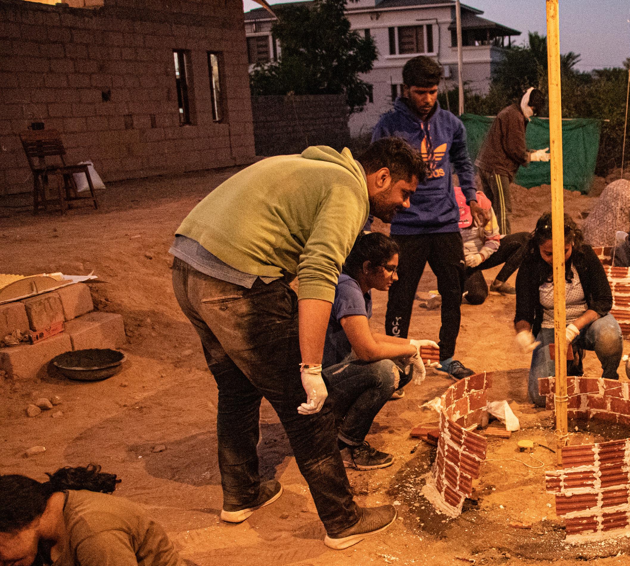
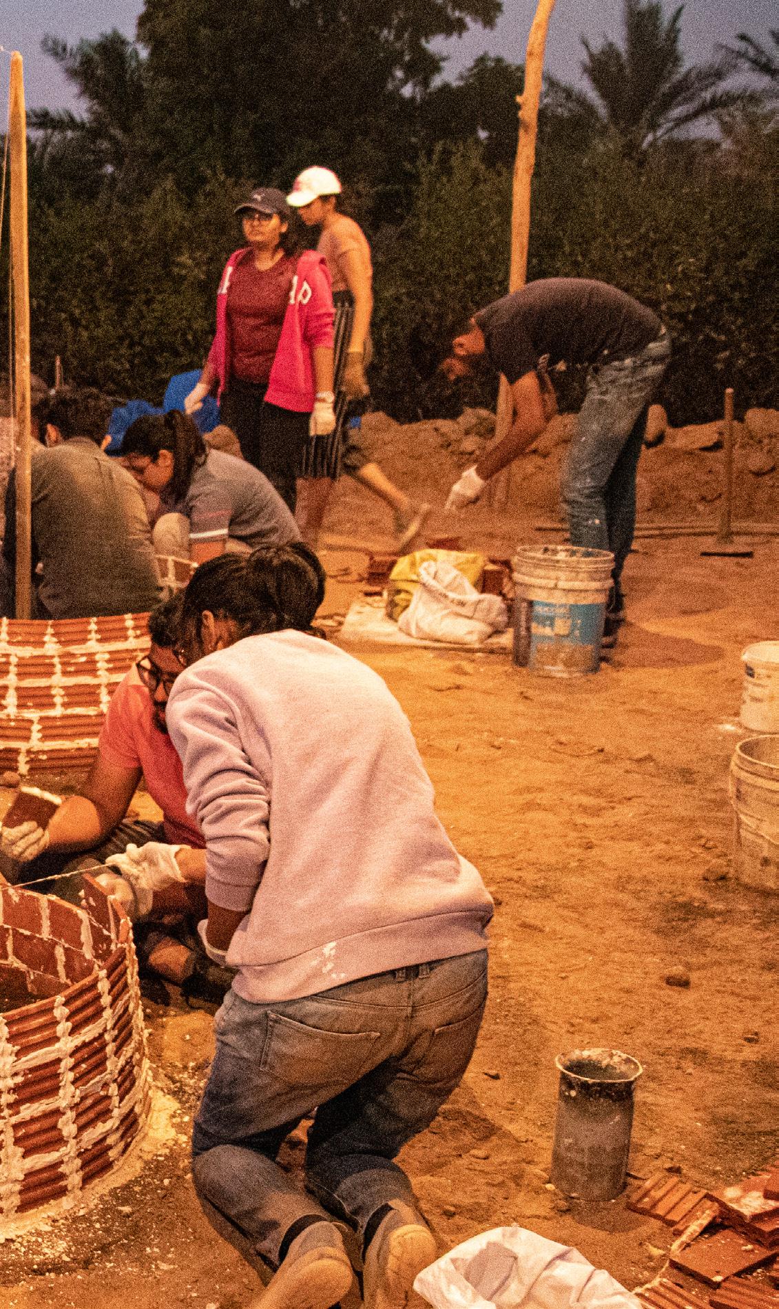
Engaging with materials is in itself a means of learning. While trying to construct the forms on-site, one learns how the drawings are translated into a physical reality. At every level of making, questions arise and their solution arrives from experimenting with the materials. How much water will it require to make slurry? How to handle tools? How much time does this take? How does the texture of the tile feel? All these kinds of questions arise while working with materials. The nature of the material is thus learned by handling it. The hands-on experience also involves us at every scale of form, from the overall dimensions to the minute detail where two or more materials come together. This chapter is a compilation of the learnings from hands-on exploration on site.
Photo Credit: Gagan Prajapati
Advertisement
Handling of material
The handling of the material on site is a very engaging process of learning materials. To handle material on-site, certain precautionary measures are to be taken. Some of the basic requirements of safety remain standard for any kind of construction process such as wearing gloves. There are certain measures to be taken based on the material properties as well.
Plaster of Paris
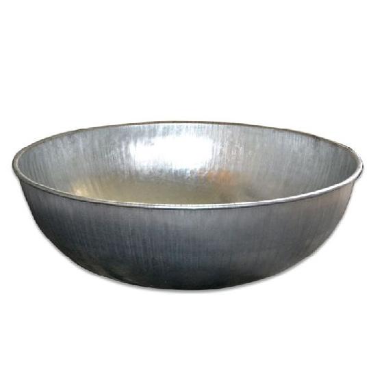
While working with Plaster of Paris it is important to wear rubber gloves as POP emits heat when comes in contact with water. Not wearing gloves while working with POP might result in dry skin. As the POP dries very fast when it comes in contact with water it is economically beneficial to make its slurry in small batches to minimize wastage. If the slurry is made in a bowl, it will be a tedious process of removing the dried off slurry while cleaning the bowl. This might even hamper the process of construction hence it is better to keep a plastic bag or waste plastic sheet as a base. Once the extra POP dries on it, one can easily dust it off and can quickly use it again. By doing so, there are fewer chances of getting dried POP crumps of the previous batch in the fresh slurry. It is very important to note that POP is added to water to make a slurry and not the other way around. If water is added to POP, then there are chances of getting lumps in the slurry.
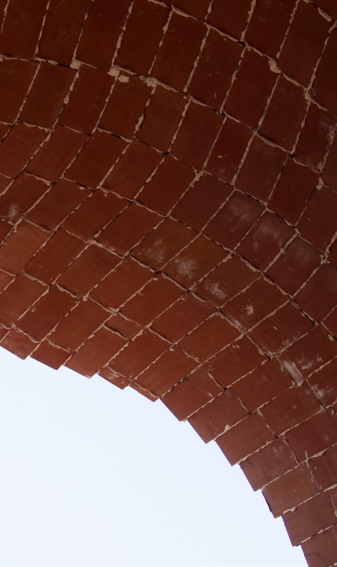
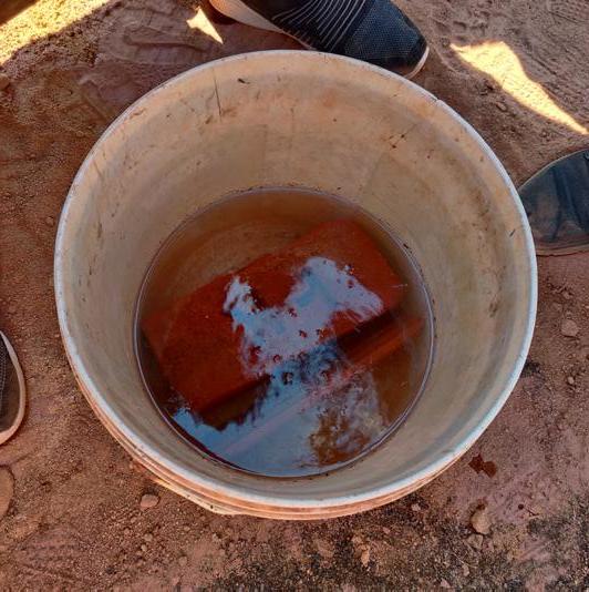
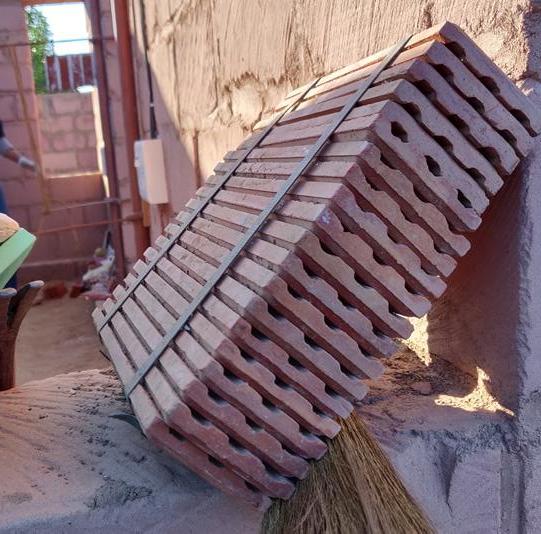
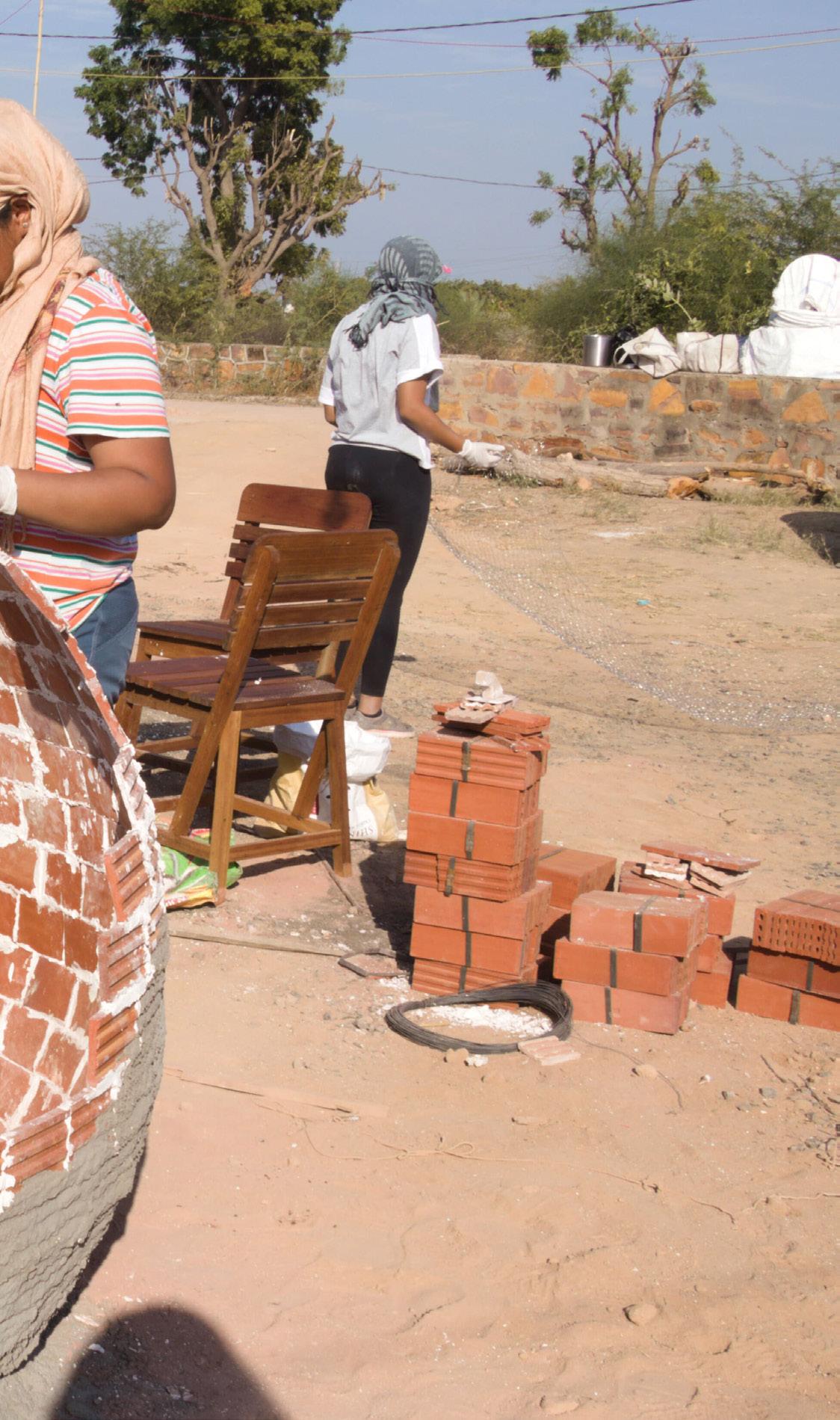
Laminated Terracotta Tile
The Laminated terracotta tiles come in a pack of 20 tiles each. It has a smooth surface on one side while on the other side it has grooves. Before using them, it is
9/25/2020 _MG_5823.CR2
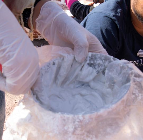
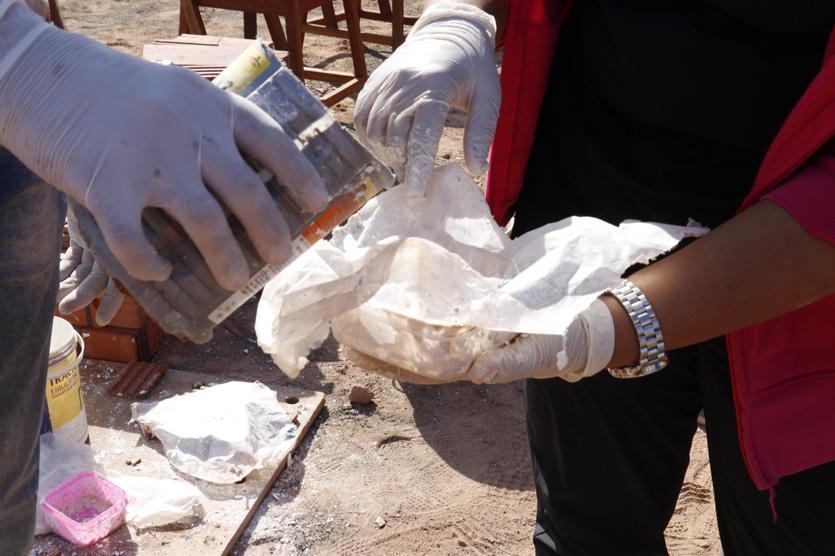
Fig 31. Adding water in POP Fig 32. Maxing PoP with water
9/25/2020 _MG_5843.CR2
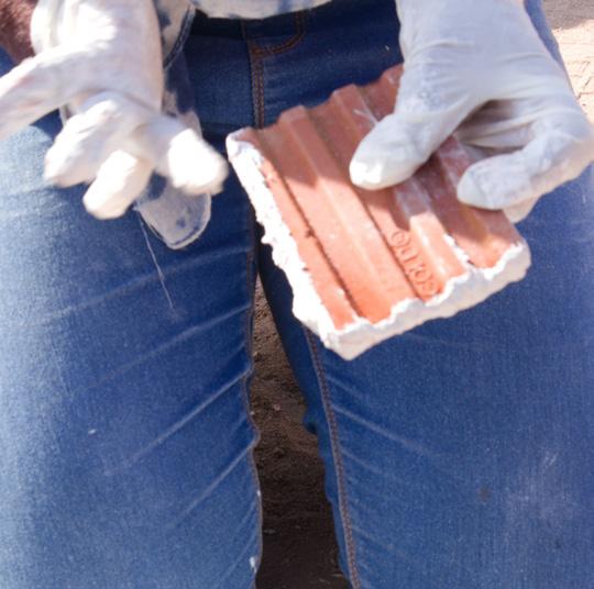
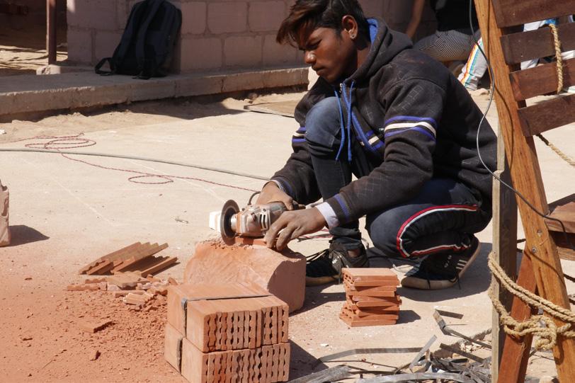
Fig 33. Applying POP on tile https://mail.google.com/mail/u/0/#inbox/FMfcgxwJXxxgkTxlpdNTCCbJpLSscfss?projector=1 Fig 34. Tile cutting 1/1
https://mail.google.com/mail/u/0/#inbox/FMfcgxwJXxxgkTxKJrvSjsQBkxhlplbf?projector=1
Fig 35. Soaking tiles in water Fig 36. Pack of tiles
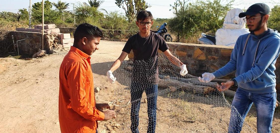
Fig 37. Stretching the chicken mesh
_MG_5967.CR2 9/25/2020 _MG_5975.CR2
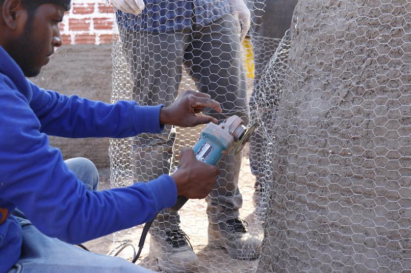
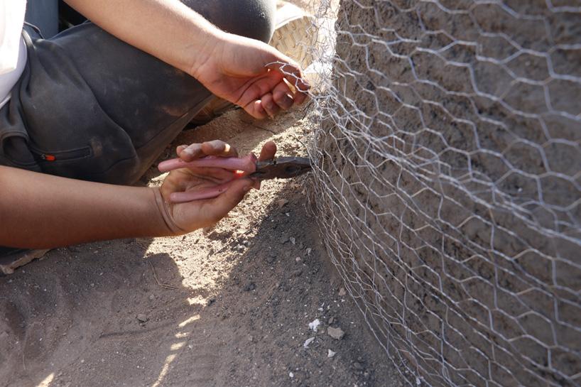
Fig 38. Cutting extra chicken mesh Fig 39. Tying mesh on the form

https://mail.google.com/mail/u/0/#inbox/FMfcgxwJXxxgkTxKSmkbDvZhLjQlKhpk?projector=1
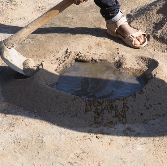
Fig 40. Filtering of sand
1/1 https://mail.google.com/mail/u/0/#inbox/FMfcgxwJXxxgkTwqstFlGGtCFGhbsNNv?projector=1 Fig 41. Making mortar necessary to soak them in a tub full of water. As terracotta tile is clay-based material, when it comes in contact to water, clay expands and hence all the air gaps get filled with water. When POP is applied, it absorbs water hence it results in a better bond between POP and terracotta tiles. The tiles when soaked, it absorbs too much water then it means that the tile is not of good quality. Depending on the scale of the form, there is a need to cut the tiles in two or more parts. It is preferable to cut the tiles using a tile cutter machine for aesthetic reasons.
Chicken Mesh
The Chicken mesh is available rolls based on fixed width and variable length. For working with the chicken mesh it is necessary to wear thick gloves to avoid cuts. First, the chicken mesh has to be unwrapped like a carpet. This requires two people, one holding the roll while the other pulling it and spreading it on the ground. Once the mesh is opened, the binding wires on the longer sides are cut at certain intervals using a plier to make it more flexible to use. The mesh is then stretched so that it becomes flexible enough to cover the form properly.
Cement Plaster
The sand used for making cement plaster has to be filtered properly using chhanni before use. To make the plaster consistent, cement, water, and sand are to be mixed. For every one bag of sand, three bags of cement are mixed. The water is added as per need until the mixture becomes consistent. The plaster should not be too thick or too watery. Once the mixture is made, it should not be kept unused for too long or it will start to get dry.
1/1
Cement Mortar
Unlike POP, cement mortar does not set quickly. It takes time to dry. The bonding agents get activated once cement reacts with water. To make cement mortar, cement is added to water and mixed well-using hands to avoid lumps. One should apply the cement mortar such that it doesn’t leave stains on the face of terracotta tiles as it might leave stains if it dries. Hence it is preferable to keep the surface of the tile clean and apply the mortar only in the grooves.
Tools
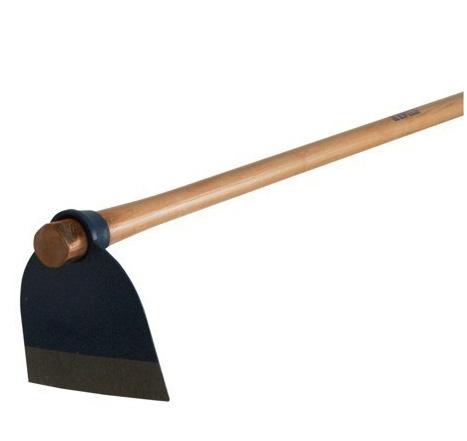
In constructing any structure, materials are not the only thing to be understood. The tools and machines used for construction are equally important. There are specific tools to be used for a specific purpose. There are various tools employed in the laminated tile shell construction technique, namely, Channi, Pawdo, Lelu, Tagaru, Olambo, Measurement tape, Pakkad, Grinder, and Cutting machine.
The Channi is used to filter the sand. There are different types of sand required for different purposes. There are different sizes of channi available. The cement mortar requires finer sand as compared to the cement plaster. To mix cement plaster, Pawdo is used. This tool is not only used for mixing cement plaster but also for removing soil after digging. It is also used to fill taggaru with sand, mortar, plaster mix, etc.
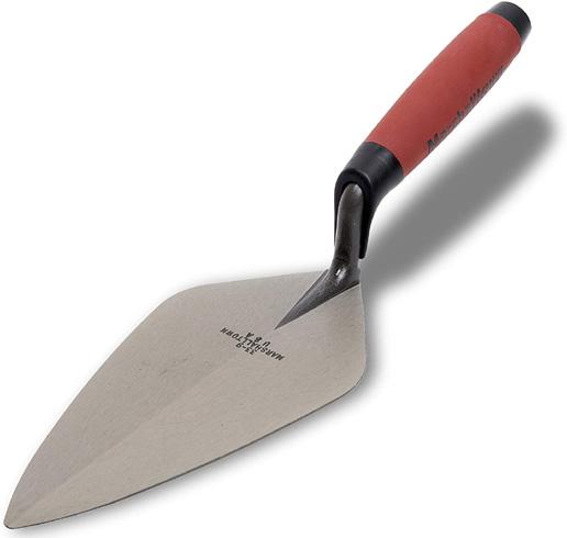
The Lelu is used to plaster as well as to apply mortar on the tiles. There are two different types of Lelu available. To mix the materials and to take materials, Taggaru is used. It also acts as a measuring unit.
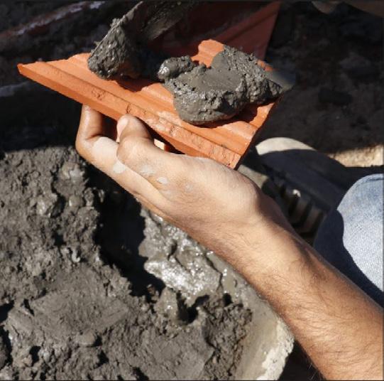
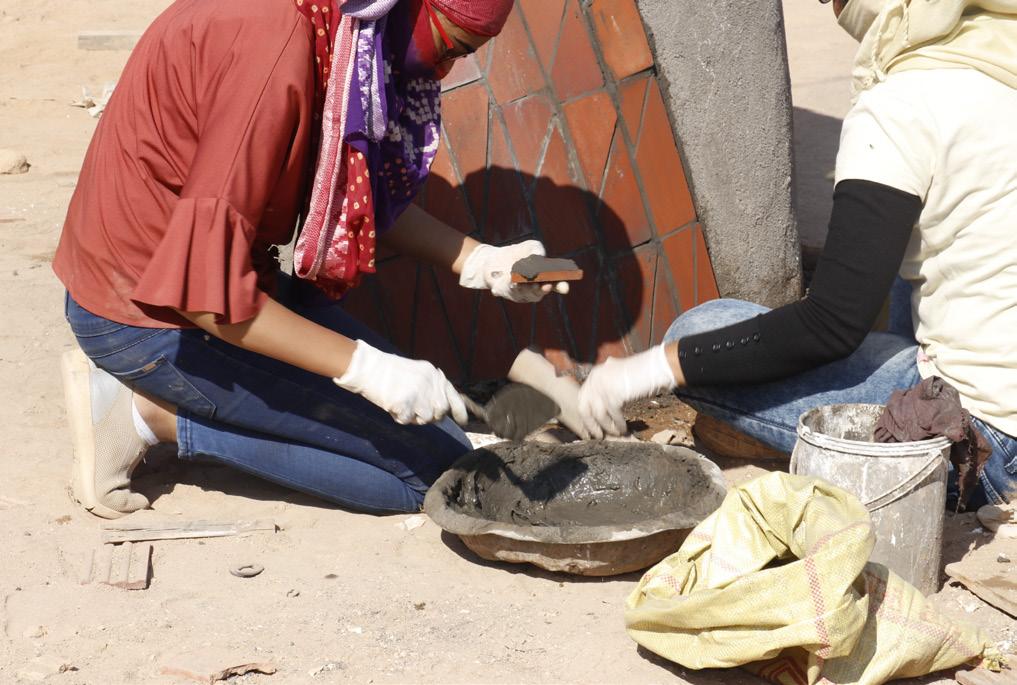
Fig 42. Applying cement mortar on tile Fig 43. Spreading cement mortar on tile
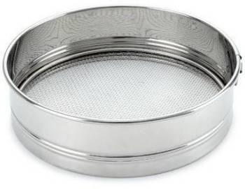
Fig 44. Channi Fig 45. Pawdo
https://mail.google.com/mail/u/0/#inbox/FMfcgxwJXxxgkTxcfQbjbMNklSLhlQrP?projector=1
Fig 46. Lelu Fig 47. Tagaru
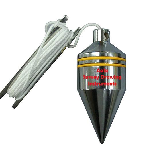
Fig 48. Olambo
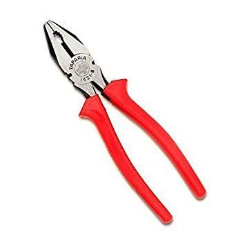
Fig 50. Pakkad
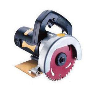
Fig 52. Cutting machine Fig 49. Measurement tape
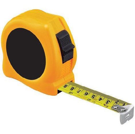

Fig 51. Grinder This tool is also used to transfer materials from one place to another on-site. The Olambo is to check if the surface is constructed straight or if there is any deviation. If the Olambo doesn’t match then necessary changes are made in the structure to make it accurate. Measurement tape helps in measuring the construction on site. There are different units of measuring tapes, the standard ones are available in feet-inches and metrics. To cut wires and chicken mesh, Pakkad is used. This tool is also used to cut wires and other such things on-site. The grinder and cutting machine are used for cutting certain materials. The grinder is a handy version of the cutting machine.
Most of the tools in construction are commonly used everywhere, the names may differ from region to region based on the spoken language of that particular region. The tools that require electricity should be operated with the utmost safety. If one learns how to operate the tools it becomes easy to work on site. Learning about tools is the primary step for working hands-on.
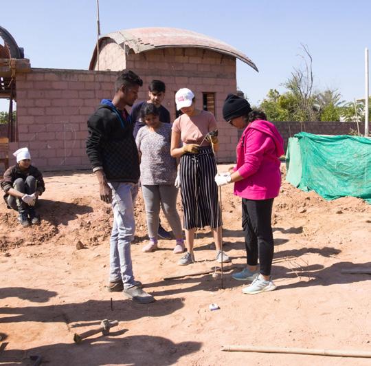
Fig 53. Marking the reference point Fig 54. Drawing curve with reference
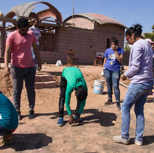

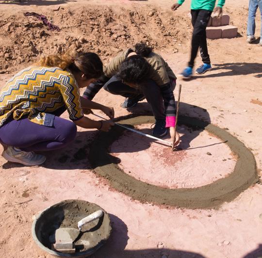
Fig 55. Marking base of the form Fig 56. Marking center line on base

Fig 57. Leveling the base Fig 58. Fixing reference rod for height

Construction Process
Base
Step 1: The base of the object is marked.
The ground is leveled and gravels are removed to make a firm base. To mark the geometry on the ground first reference point is marked using a metal rod or a wooden stick. If its a circular form then one end of a string is tied at the base of the first reference point while the other end is tied to a sharp stick or a pencil. The length of the string has to be equal to the length of the radius. Then a circle is drawn using these two sticks and string such that its as accurate as possible.
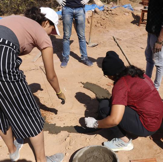
Step 2: The base of the object is made.
Once the base is marked, a layer of cement mortar is laid on that acts as a foundation. The center of the form is then marked by putting a straight stick or a metal rod.
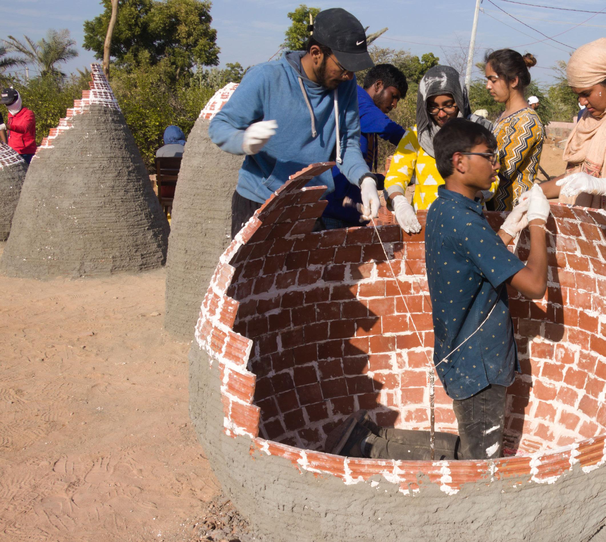
TheFirst Layer Construction
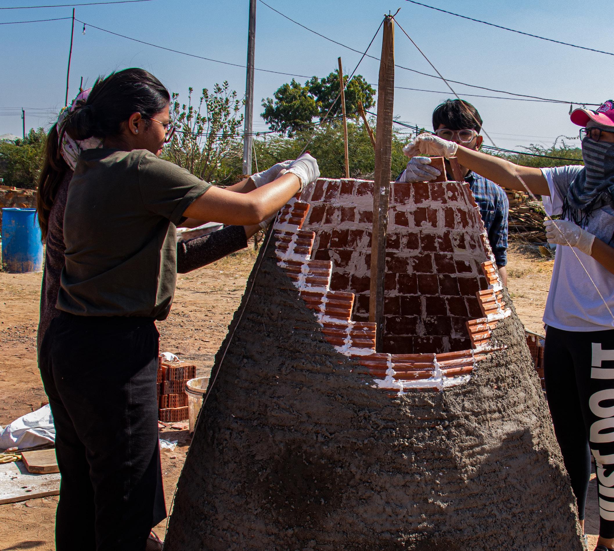
Step 3: The first layer of tiles is laid.
When the cement mortar dries, the first layer of tiles is laid using tiles and POP. The POP is applied on two adjacent sides of the tile and is held for a while to let the POP setting. The tiles are placed such that the plain face of the tile is on the inside. Here the POP is made in small batches in a quantity that can fix 3-4 tiles at a time. If more amount of POP is made then it dries off and becomes unusable.
Step 4: The use of a guide to check the dimensions.
It is necessary to keep a check on the dimensions. The guide should be used for laying the tile. This guide helps the tile to attain the angle and shape of the form. The type of guide changes based on the form that is being constructed. A measuring tape is also used as and when required for marking reference dimensions on the guides. Fig 59. The layer of tiles is laid
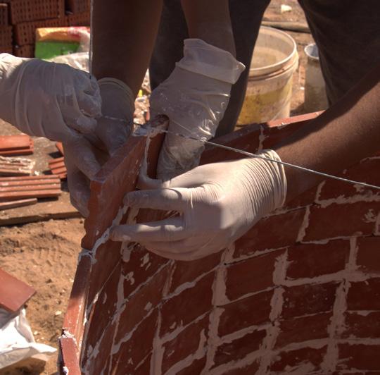
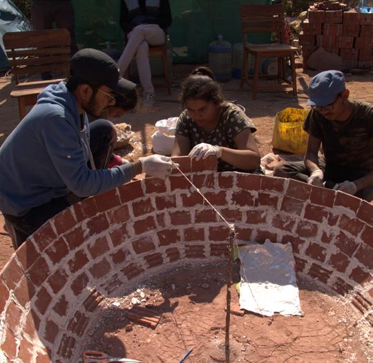

Fig 61. Applying PoP on tile
Fig 63. A guide is use Fig 60. Checking dimensions

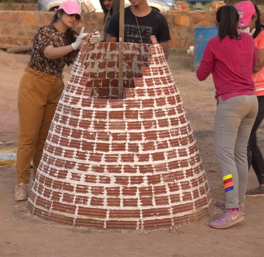
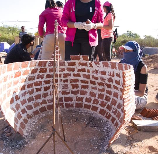
Fig 62. Layering of tile
Fig 64. First layer of construction
TheSecond Layer Construction
Step 5: The first layer of plaster.
Once the form is attained by layering the terracotta tiles, the whole form is plastered with cement plaster. The layer of the plaster is around 5-6mm. The plaster layer makes it a monolithic structure.
Step 6: To wrap the chicken mesh around the form.
When the plaster layer dries, the chicken mesh is wrapped on the form. The grinder is used to cut off the extra chicken mesh and the plier is used to attach the wire mesh around the form.
Step 7: The second layer of plaster.
The chicken mesh is covered with a layer of cement plaster of approximately 5-6mm. This makes the plaster layer 12-14mm thick including the chicken mesh. By doing so the form attains tensile strength that converts the brittle failure into a plastic or elastic failure.
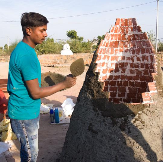
Fig 65. Applying cement plaster Fig 66. To wrap the chicken mesh
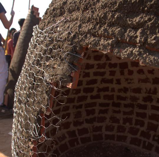

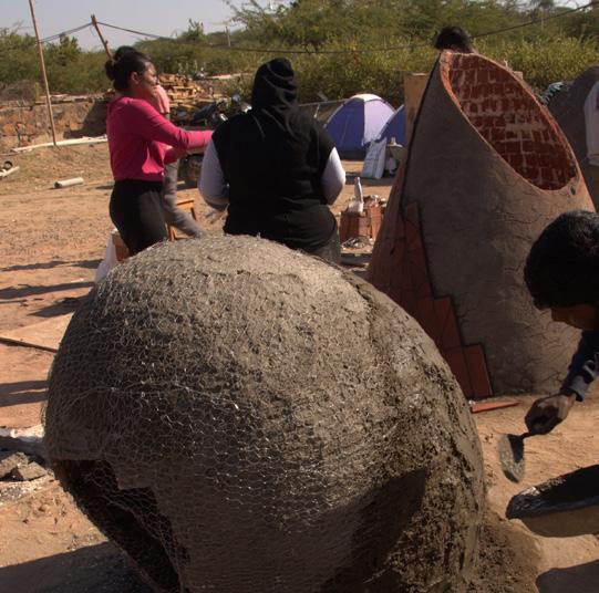
Fig 67. Tying the chicken mesh Fig 68. Second layer plaster
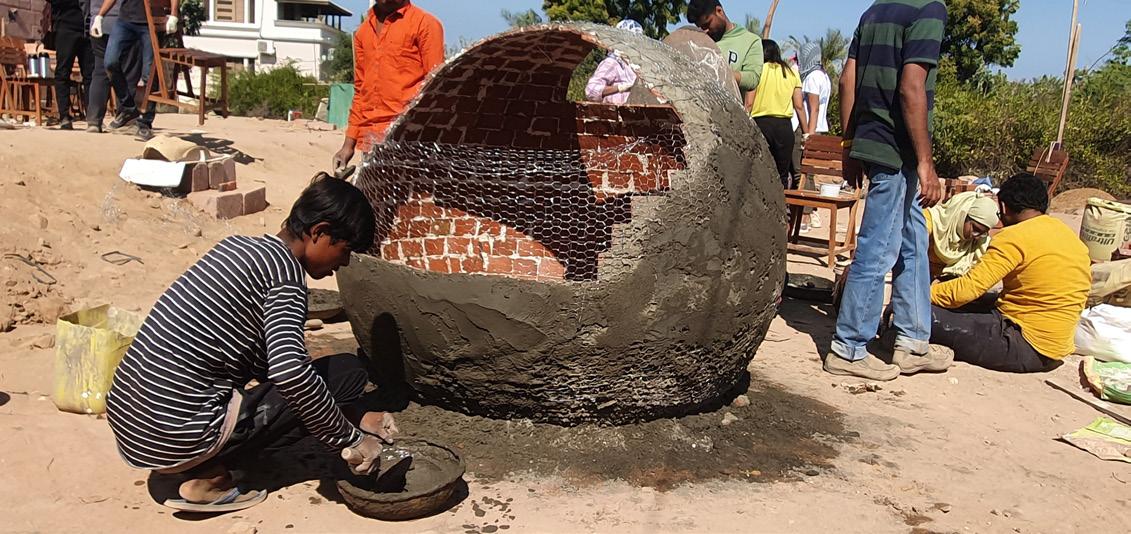
Fig 69. Covering the form with cement plaster
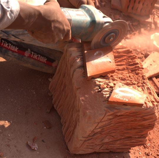
Fig 70. Tile cutting Fig 71. Applying cement mortar
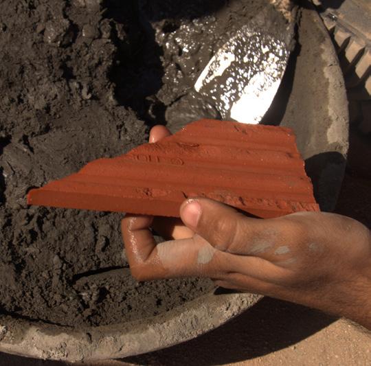
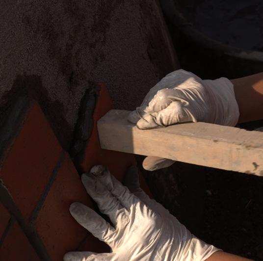
Fig 72. Removing air gaps
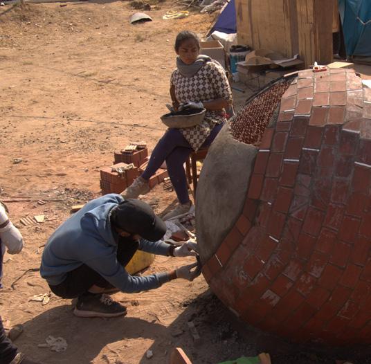
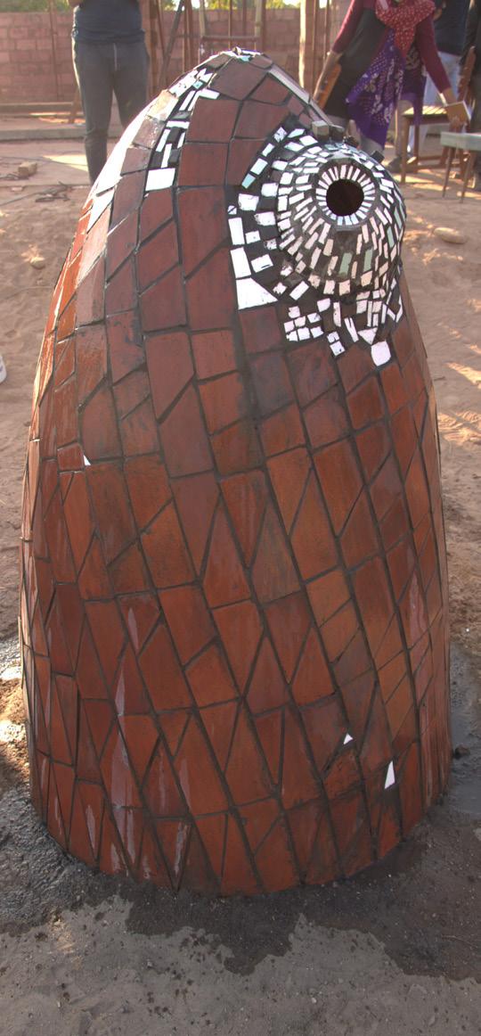
Fig 73. Cladding the form with tile Fig 74. The finished form The third layer of construction
Step 8: Cladding of terracotta tile.
The plaster is then covered with terracotta tile such that the finished surface is facing the exterior. Cement mortar is used to clad the tiles. Here the tiles can be clad to form the desired pattern on the surface.
Step 9: Cutting terracotta tiles.
To cover the surface using terracotta tiles, the parts where the tile doesn’t touch the surface, the tile has to be cut into parts to cover that area.
Step 10: Filling the groove.
The grooves between the tiles are filled using cement mortar. The face of the tile is cleaned simultaneously so that there remain no stains of mortar on the finished surface.
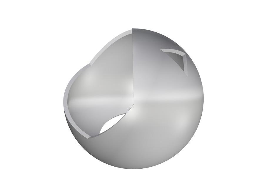
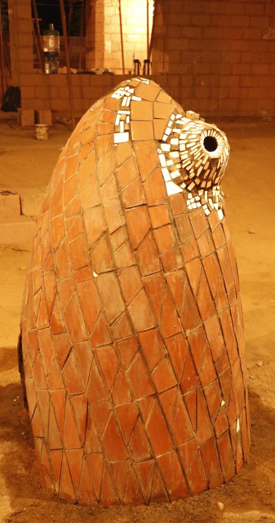
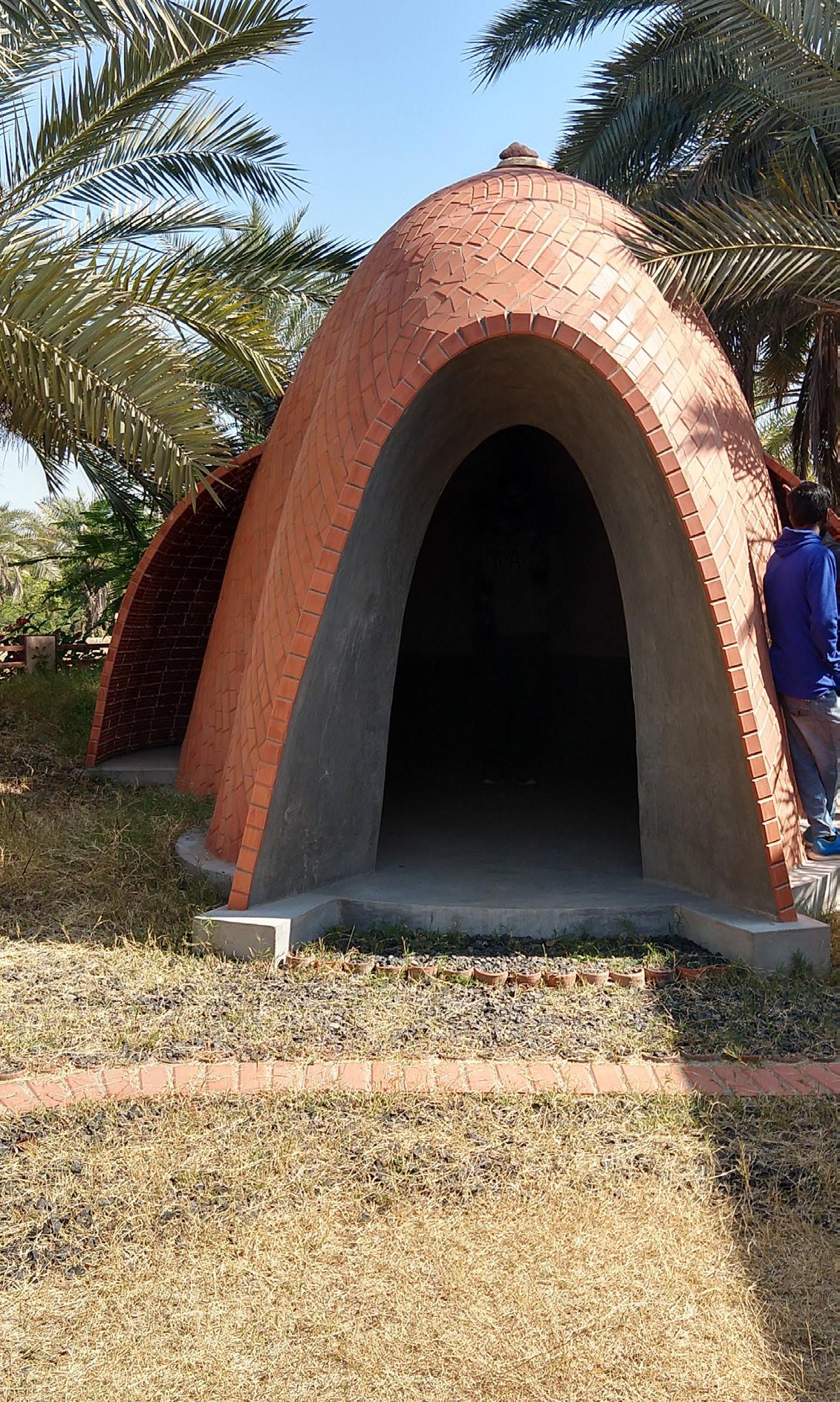
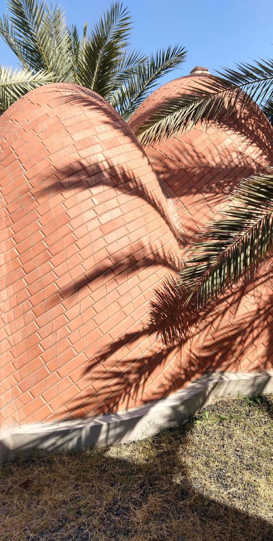
Sphere
A sphere is a surface generated by rotating the circle 360 degrees along a fixed axis. All the points on the surface of the sphere are equidistant from the center of the sphere. Any section that is cut from a sphere, gives a circular cut out. A sphere has curvature and the maximum area is obtained at the center of the sphere. Hemisphere is obtained by dividing the sphere into two equal parts. To make a sphere, the center of the sphere is the most important point. It has to be used as a guide in order to construct the surface of any spherical form.
Photo Credit: Gagan Prajapati
Conceptual Sketches
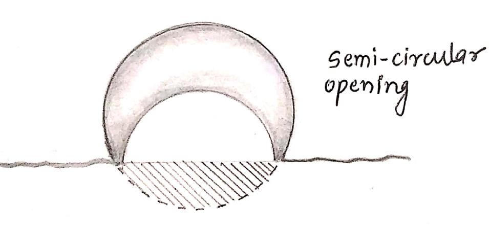
Fig 75. Initially, the conceptual position of the void was explored using sketches. The idea was to have openings of different sizes for different purposes. The first sketch shows a semicircular opening with the sphere submerging in the ground. By pushing the sphere in the ground, the form can have stability.

Fig 77. The semi-circular opening was becoming a very large void in the overall form hence the opening was transformed into a circle. Here the size of the radius of the void was taken almost half of the sphere. The idea was to have two circular openings in such a manner that one can see through that void.
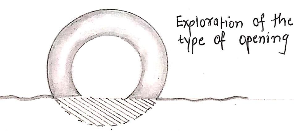
Fig 76. The opening on the side was decreasing the strength and stability of the spherical form. The height of the placement of the void was further explored to solve the problem.
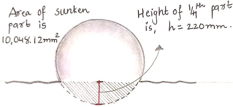
Fig 78. To provide more stability, the shape was again pushed deeper into the ground. By doing so the surface area touching the ground increased, which acts as a stable base for the form to rest on.
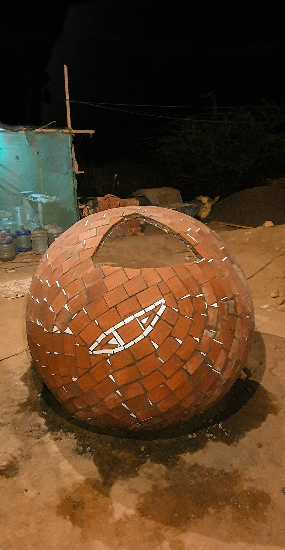
Fig 79. After going through the initial stages of conceptualization, the final spherical form was arrived at. The overall height of the form above the ground level was kept at 1200mm. The radius of the sphere was derived as 710mm as per the availability of tiles and the surface area of the sphere.
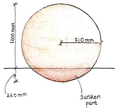
Fig 80. The void was kept in such a manner that the stability of the form does not decrease. The above sketch shows the elevation view of the form from the side.
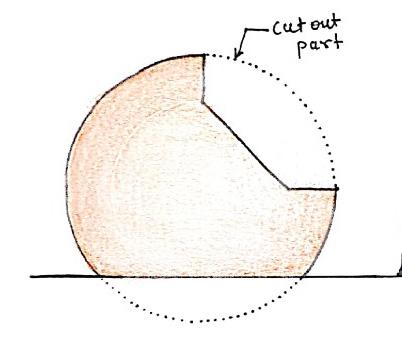
Fig 81. The void when looked at from the front view, one can see how its height is for a human scale. One can easily peep into the void.
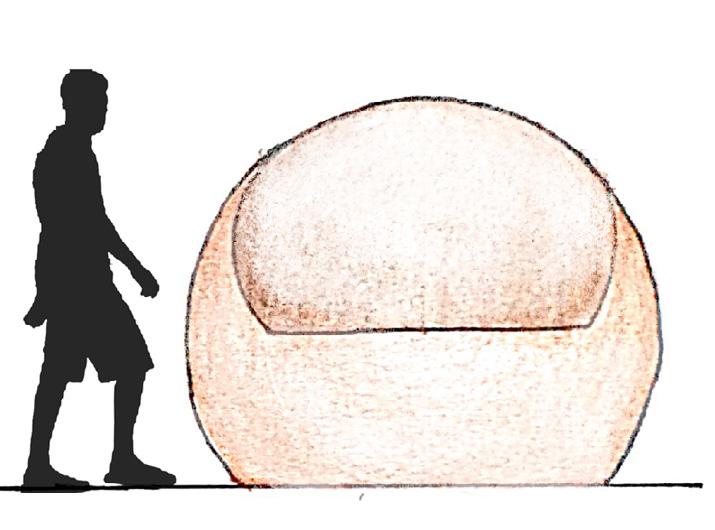
Sketches & Calculation
Radius of Sphere (r) = 710 mm Height of Sunken part (h) = 220 mm Tile dimensions = 230 mm x 75 mm x 15 mm Surface Area of Tile = 230 x 75 = 17250 mm
No. of Tiles used per Sphere = 500 tiles No. of Tiles used on each side = 250 tiles Surface Area of Tiles on each side = 17250 x 250 = 43,12,500 mm2
Surface Area of Sphere = 4πr2 = 4 x 3.14 x ( 710 )2 = 63,31,496 mm2
Surface Area of Spherical Cap = 2πrh = 2 x 3.14 x 710 x 220 = 9,80,936 mm2
Surface Area of Sphere (Above ground) = S.A. of Sphere – S.A. Spherical Cap = 6331496 – 980936 = 53,50,560 mm2
Surface Area of Sphere = Surface Area of Tiles on Each side = 43,12,500 mm2
Area of Cut out on Sphere = S.A. of Sphere (Above ground) – S.A. of Form = 5350560 – 4312500 = 10,38,060 mm2
Final Drawings
Fig 82. Plan of sphere
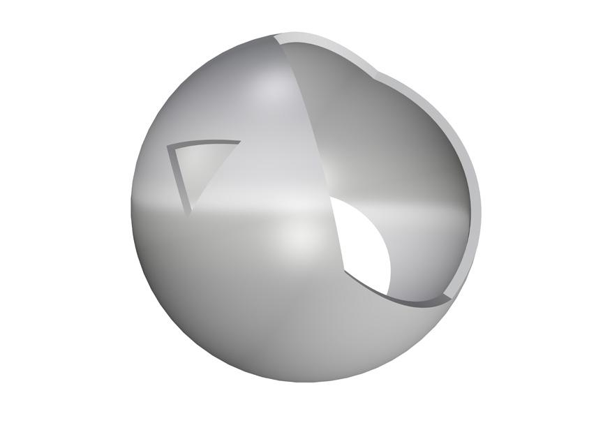
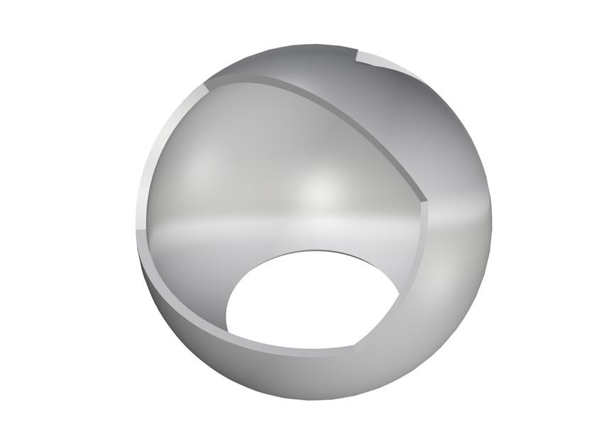
Fig 83. Section of sphere Fig 84. Exploded view of sphere

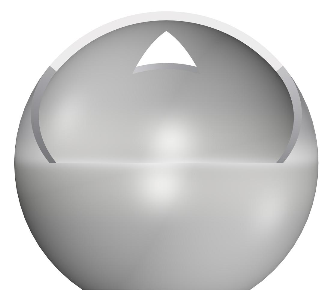
Fig 85. Elevation of sphere Fig 86. 3D views of sphere
To construct the spherical form on site, the base of the form is marked on the ground using a stick. A thread of the length of the radius is tied on one end of the stick while the other end of the stick is kept on the ground. Then a pencil or another sharp stick is attached to the other end of the thread. Using this device as a compass, a circle of 710 mm radius is drawn on the ground. A straight stick of the 1420 mm length is fixed in the center of the circle. Now a thread of the radius of the sphere is tied on the stick. This thread acts as a guide for constructing all the points on the surface of the spherical form. The layers of tile along with POP slurry are laid horizontally.

Fig 87. Marking base on ground
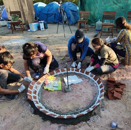
Fig 89. First layer of tiles Fig 88. Marking guide for reference
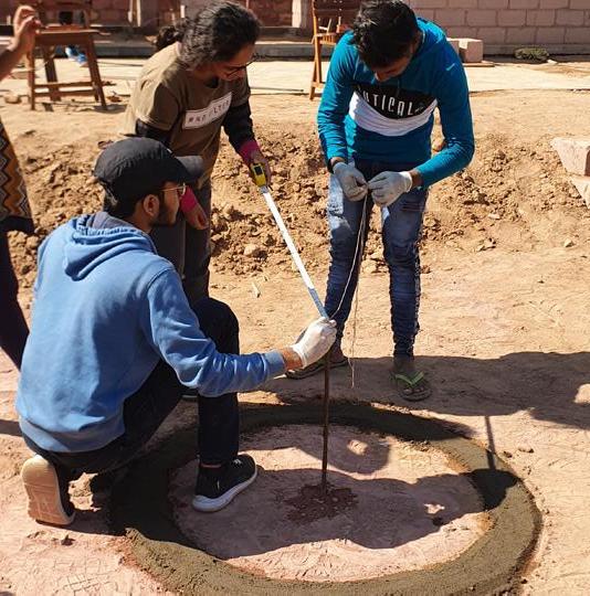
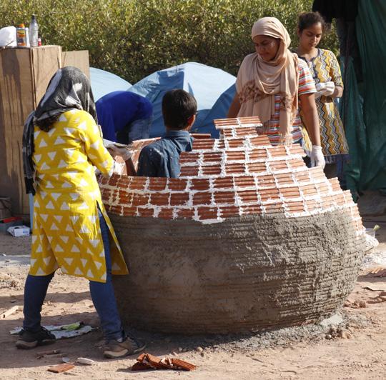
Fig 90. Layering of tile
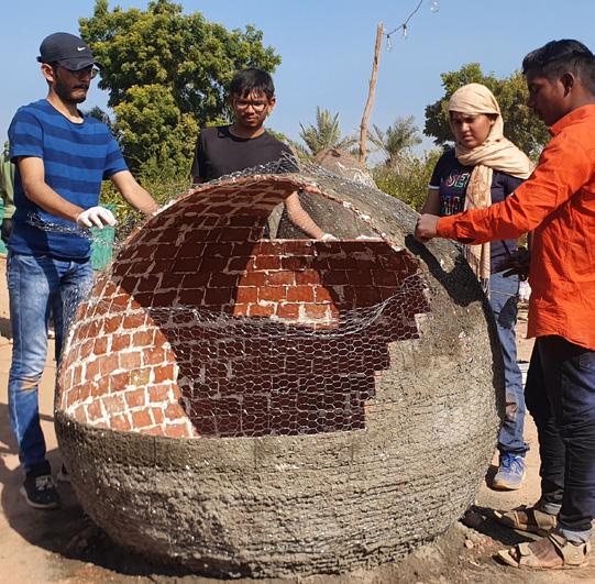
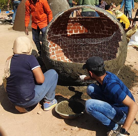
Fig 91. Wrapping chicken mesh Fig 92. Second layer of plaster
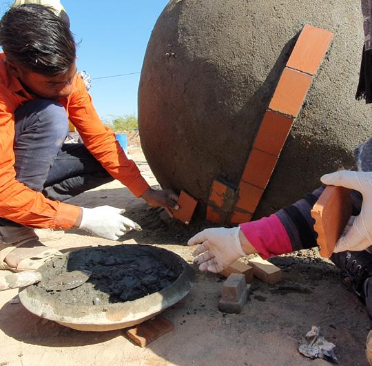
Fig 93. Cladding tile on surface Fig 94. Tile claded surface


Fig 95. Cladding in process Fig 96. Finished sphere Fig 97. Finished spherical form
Catenary
The catenary curve is formed using a rope, wire or a chain hanging freely from two points forms a U shape. The 2d shapes and the 3d forms are strong because they redirect the vertical force of gravity into compression forces pressing along the arch’s curve. A catenary is a stable shape as compared to a hemisphere.
Photo Credit: Gagan Prajapati
Conceptual Sketches
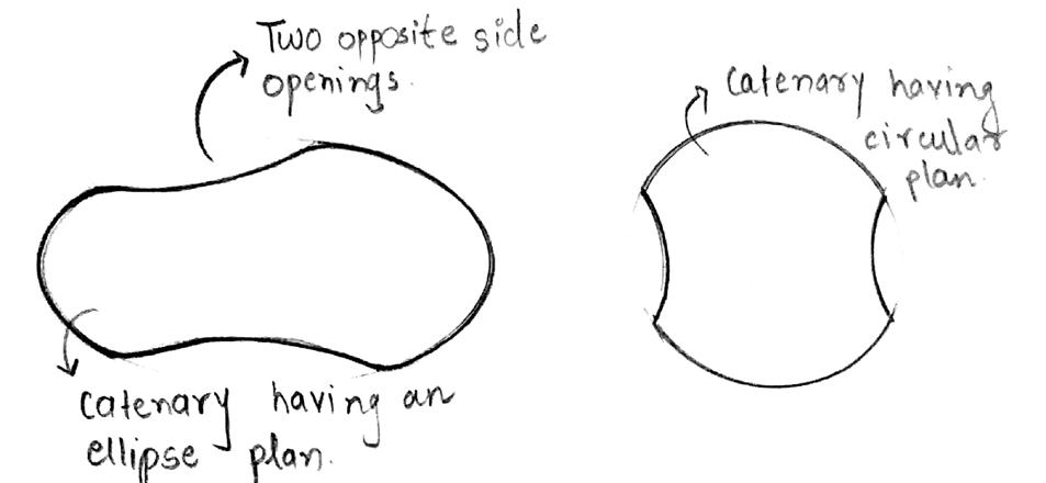
Fig 98. The designing of form started with plan, to decide the orientation of the openings and the shape of the base. The initial idea was to create a bridge like structure with openings on either sides. As the catenary form was not stable with that large amount of void, the amount of void was decreased
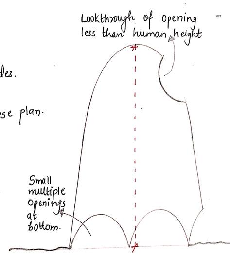
Fig 99. The openings were designed based on the human scale. A small opening is created at the base for children. The opening on the higher level was created such that one can peep inside the catenary form.
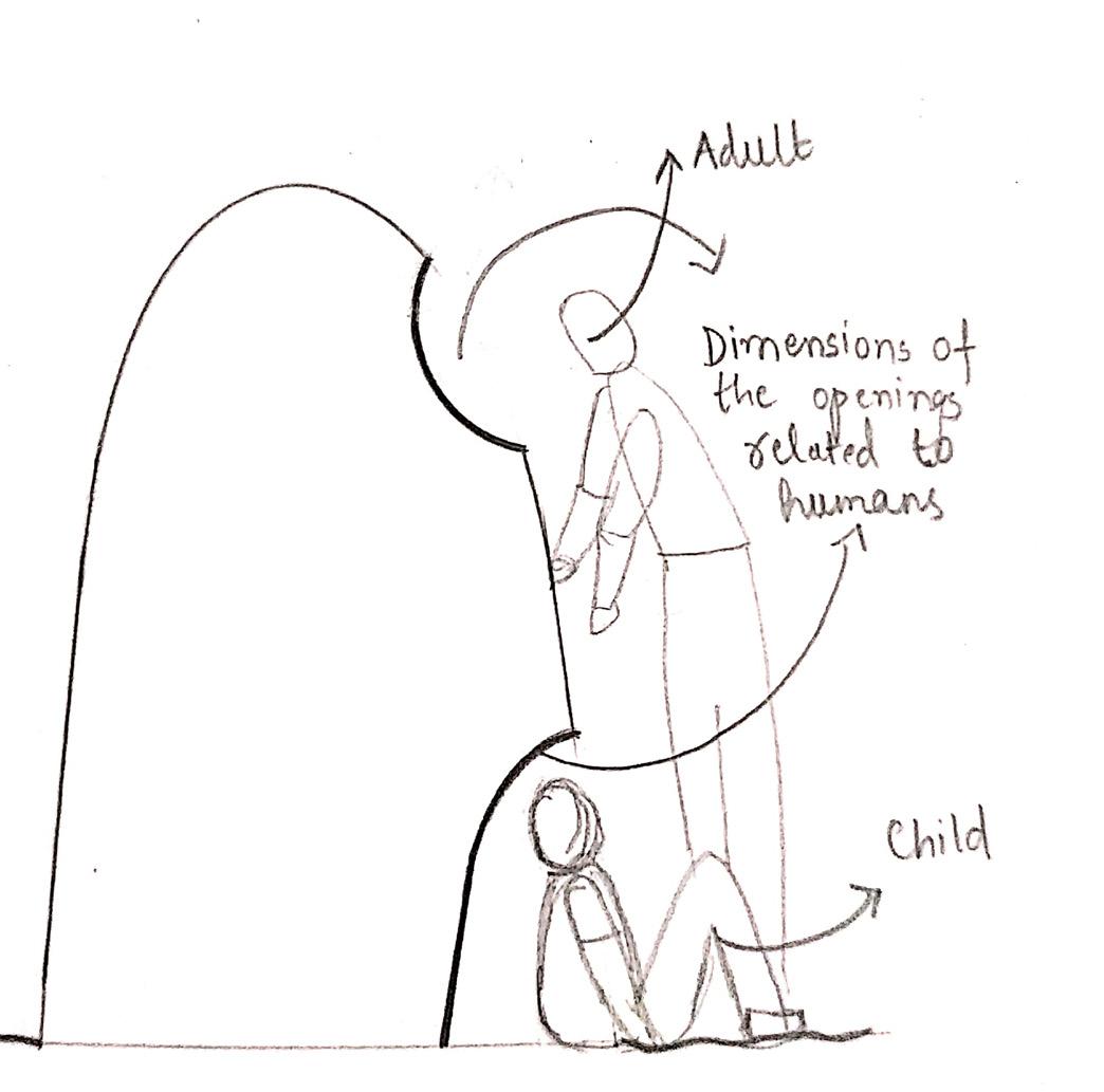
Fig 100. Having multiple openings at the bottom of the form was also explore through sketches. The problem here was that if the base is punctured a lot then the structural stability of the form decreases.
Fig 101. Finally, the radius of the form is decided as 500mm, and the height as 1500mm based on the number of tiles available.

Fig 102. The cut-outs are placed in such at the base of the form. There is a void on the top of the form as well so that one can peep through.
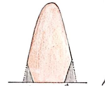
Fig 103. The height of the form is almost the height of the human eye level. The view above shows how one can stand beside the form as support.

Sketches & Calculation
Radius of Paraboloid (b) = 500 mm Height of Paraboloid (a) = 1500 mm
Tile dimensions = 230 mm x 75 mm x 15 mm Surface Area of Tile = 230 x 75 = 17250 mm2
No. of Tiles used per form = 450 tiles No. of Tiles used on each side = 225 tiles
Surface Area of Tiles on each side = 17250 x 225 = 38,81,250 mm2
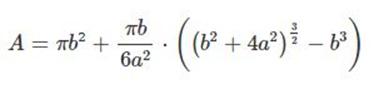
Surface Area of Paraboloid :
= 40,44,250 mm2
Surface Area of Form = Surface Area of Tiles on Each side = 38,81,250 mm2
Area of Cut out on Form = S.A. of Cone – S.A. of Form = 4044250 – 3881250 = 1,63,000 mm2
Final Drawings
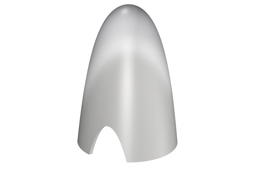
Fig 104. Plan of catenary
Fig 105. Section of catenary Fig 106. Exploded view of catenary
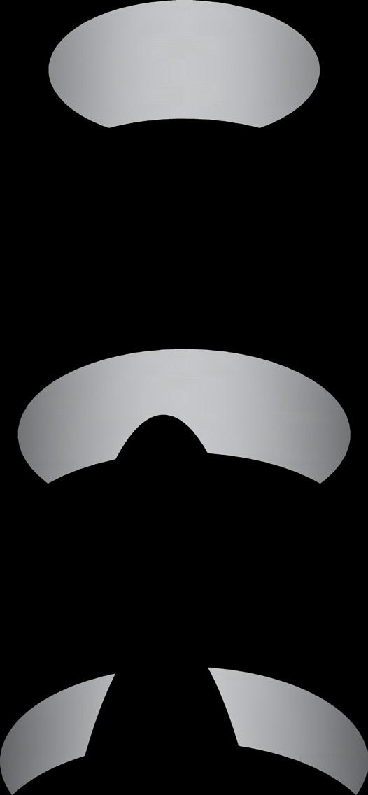
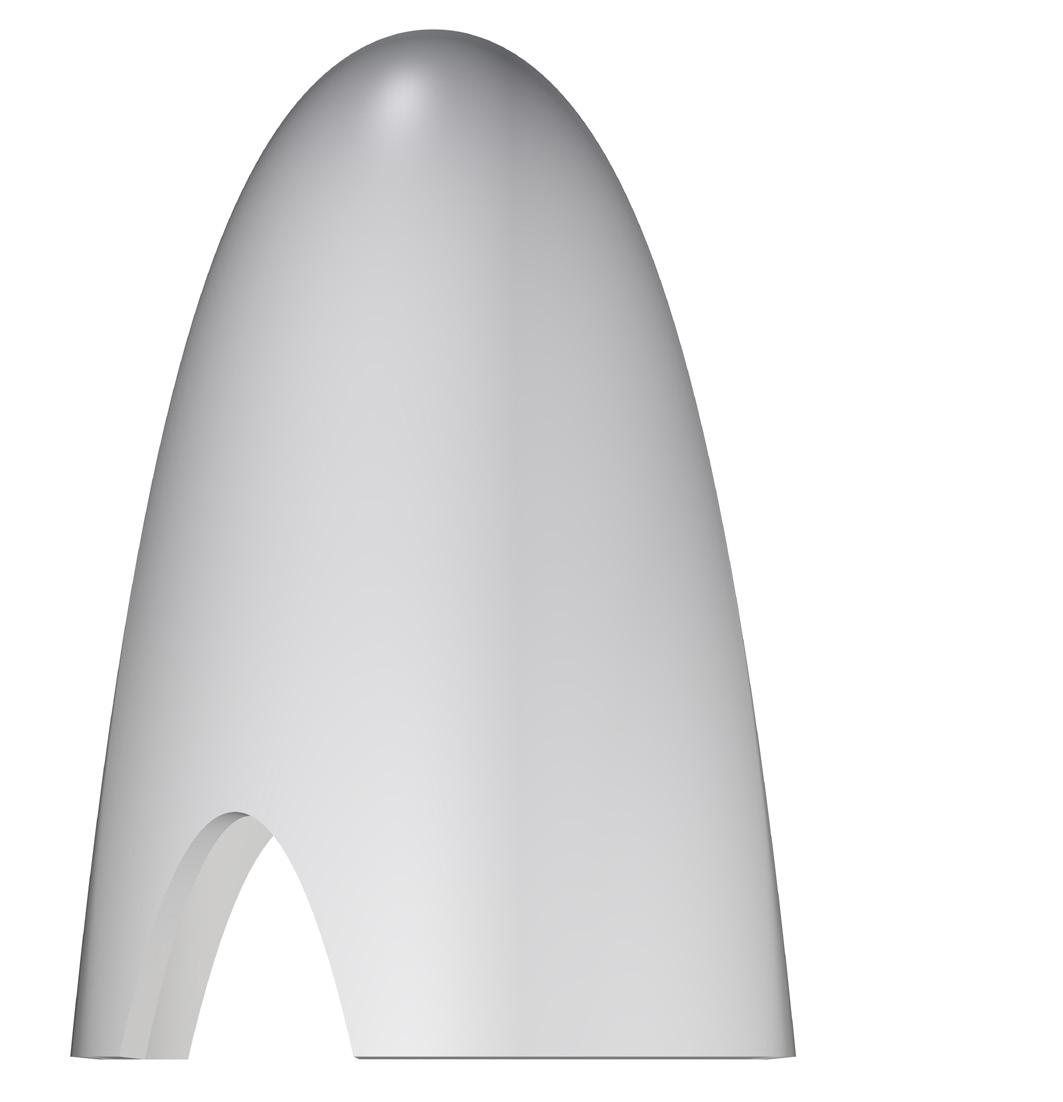
Fig 107. Elevation of catenary Fig 108. 3D views of catenary


To construct the catenary form, first, the base of the form is marked on the ground. A thread of the length of 500 mm for the base is tied on a straight stick. The other end of the thread is tied on another stick. Using this device, a circle is drawn on the leveled ground. A straight metal rod is fixed at the center of the circle. The rod is then marked with points with equal intervals of tile heights for reference. A wire is tied around the rod to mark the radius for the changing heights. The layers of terracotta tiles using POP slurry is constructed horizontally to form the catenary form. The radius of the form is checked while laying every tile. The radius of the form keeps on decreasing as the form develops vertically.

Fig 109. Making base on ground
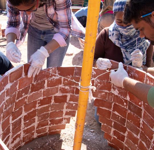
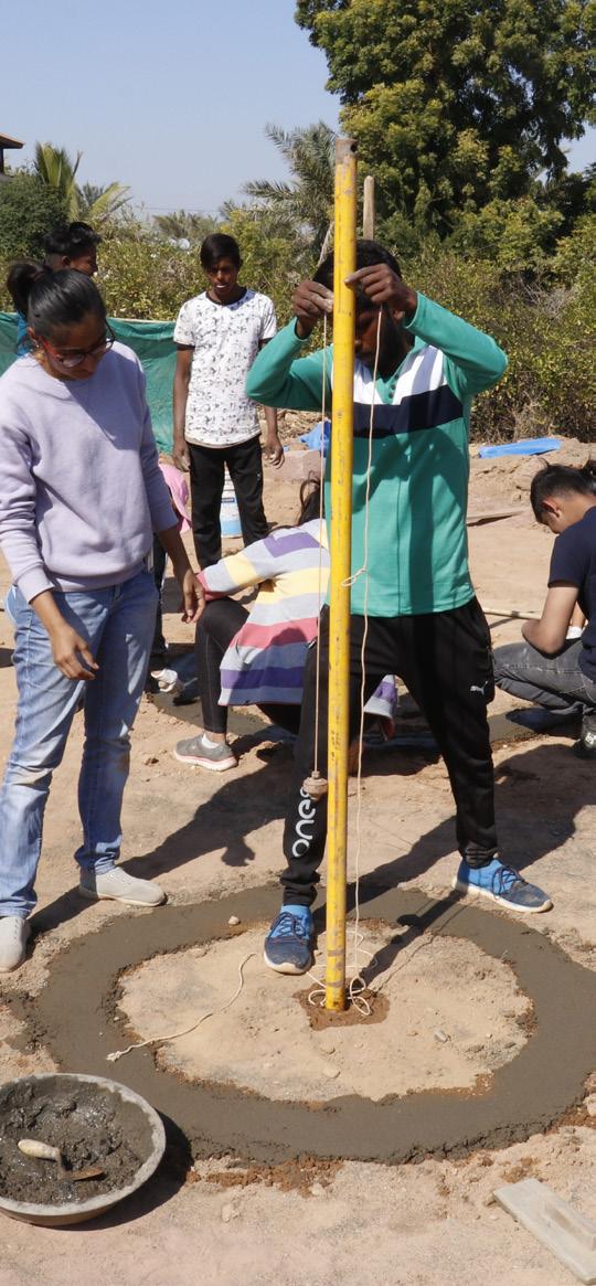
Fig 111. Checking with guide Fig 110. Fixing vertical guide
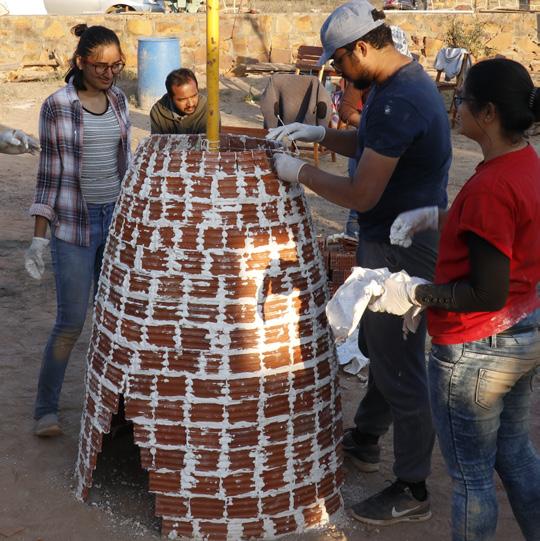
Fig 112. First layer of tiles Fig 113. First layer of plaster
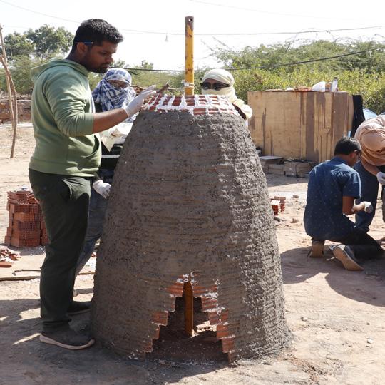
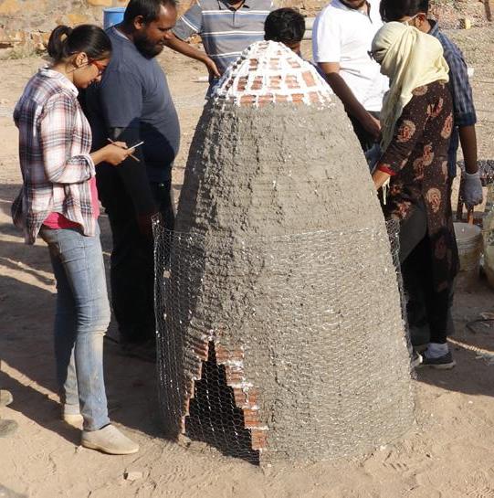
Fig 114. Chicken mesh layer Fig 115. Tile cladding
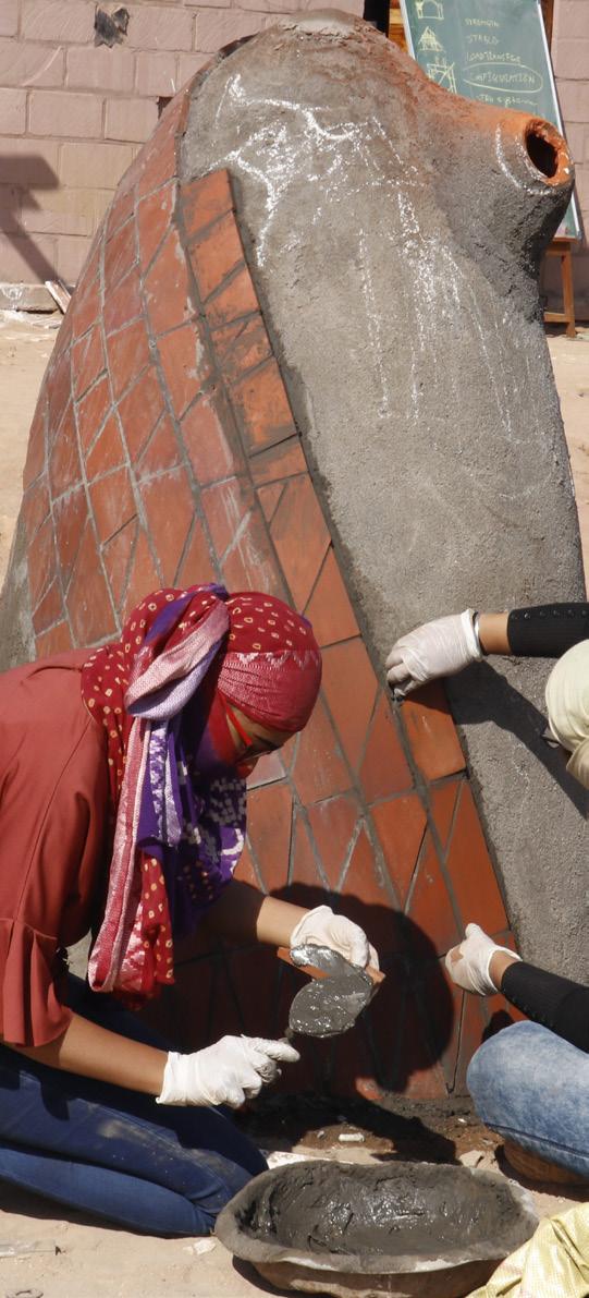
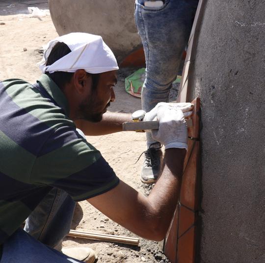
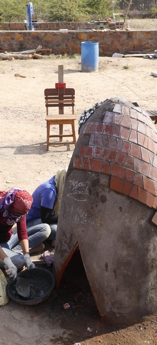
Fig 116. Applying cement mortar Fig 117. Second layer of tile Fig 118. Finished catenary form
Ellipsoid
An ellipse is an oval-shaped closed curve. The two foci of an ellipse are the main points for achieving the form. Both the foci are at equidistance, which makes the form stable. The present form design includes the two guides placed equidistance that acts like foci of the design. There was a structural challenge to tilt the form at a certain angle keeping one focus at the ground to stabilize the form. The special character about this type of form is that if a person standing is at one focus and another person on other focus, then one can hear a person standing on opposite foci. Due to the reflective property of Ellipse.
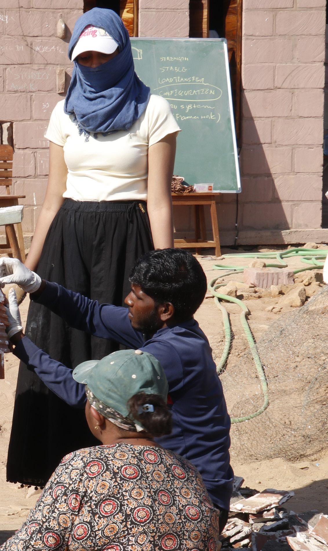
Photo Credit: Gagan Prajapati
Conceptual Sketches

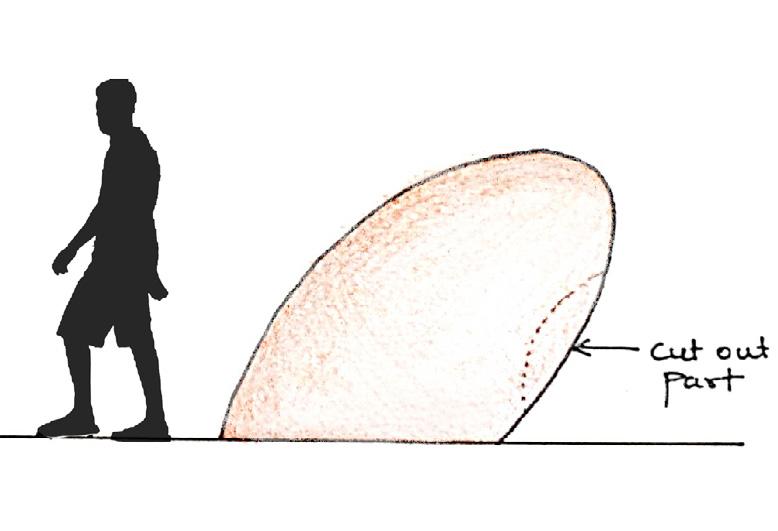
Fig 119. The form of the object was explored by tilting it such that one-fourth of the form goes inside the ground. The openings were thought of as voids on either side such that one can see through.

Fig 120. To have a stable form it is necessary to tilt it at a specific angle or else the form might collapse. The angle of the tilt was decided based on that.
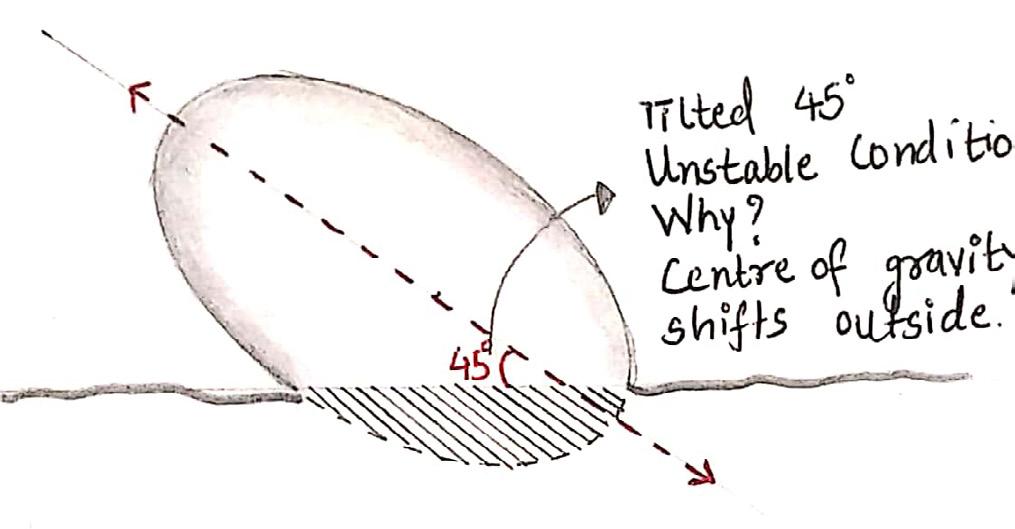
Fig 121. The first focus is kept on the ground such that it forms a 30-degree angle with the ground line. The opening is then placed in such a manner that it changes the character of the form and its experience as well. The opening is big enough for children to sit inside the form.
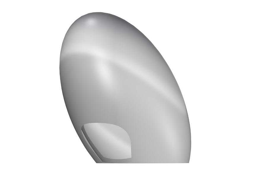
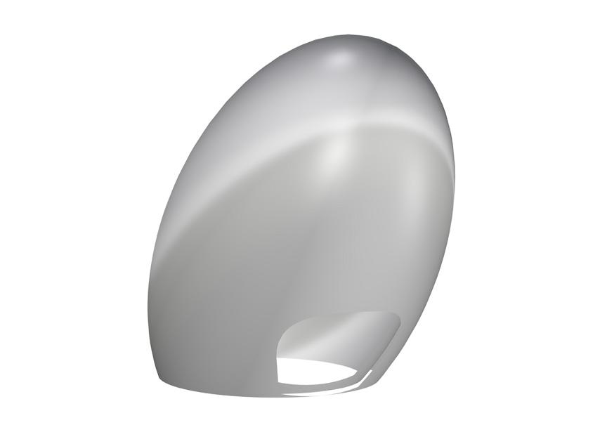
Fig 122. The above sketch represents the ellipsoid with the longer axis vertically. It is not possible to construct the form without a proper base.
Fig 123. To support the form, the ellipsoid is tilted at an angle of 45 degrees to have a firm base. The ellipsoid is sunken in the ground for better stability.
Fig 124. The opening was placed almost at the bottom of the form. The height of the ellipsoid is such that one can sit on it.
Sketches & Calculation
Major Axis = 1820 mm Minor Axis = 900 mm Foci (f) = 620 mm Axis a = 910 mm Axis b = 450 mm Axis c = 450 mm
Tile dimensions = 230 mm x 75 mm x 15 mm Surface Area of Tile = 230 x 75 = 17250 mm2
No. of Tiles used per form = 400 tiles No. of Tiles used on each side = 200 tiles Surface Area of Tiles on each side = 17250 x 200 = 34,50,000 mm2
Surface Area of Ellipsoid : ,where, p = 1.6 = 43,91,047 mm2 Surface Area of Sunken Part = 7,45,191 mm2
S.A. of Ellipsoid (Above ground) = S.A. of Ellipsoid – S.A. of Sunken part = 4391047 – 745191 = 36,45,856 mm2
Surface Area of Form = Surface Area of Tiles on Each side = 34,50,000 mm2
Area of Cut out on Form = S.A. of Ellipsoid (Above ground) – S.A. of Form = 3645856 – 3450000 = 1,95,856 mm2
Final Drawings

Fig 125. Plan of ellipsoid

872 mm
Fig 126. Section of ellipsoid Fig 127. Exploded view of ellipsoid
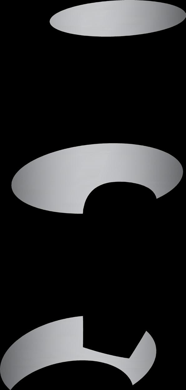
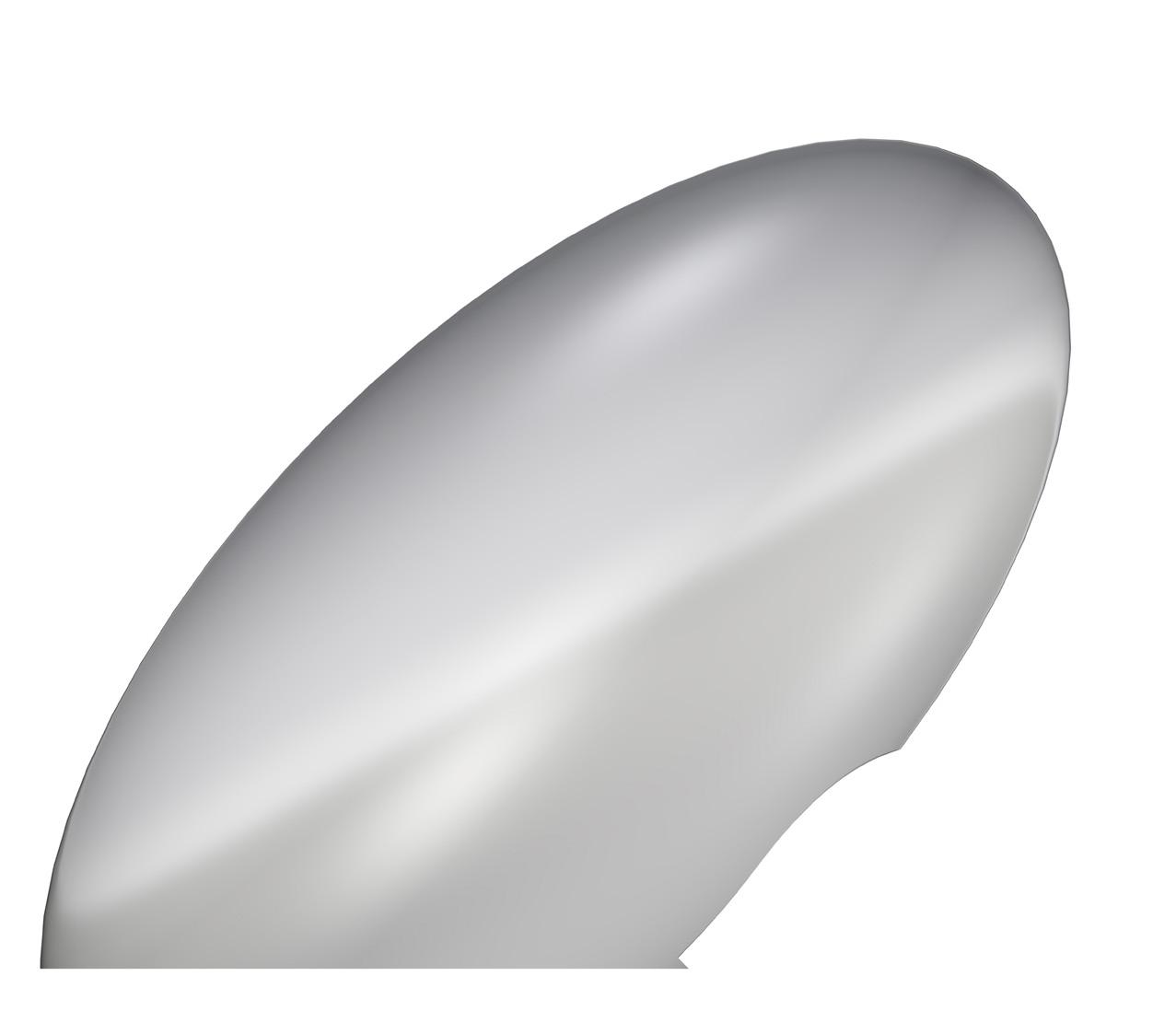
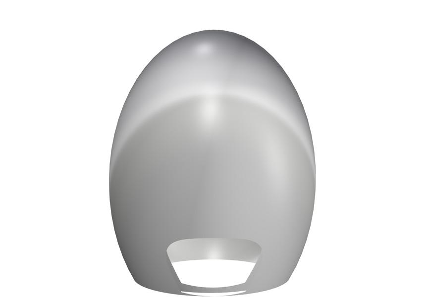
Fig 128. Elevation of ellipsoid Fig 129. 3D views of ellipsoid
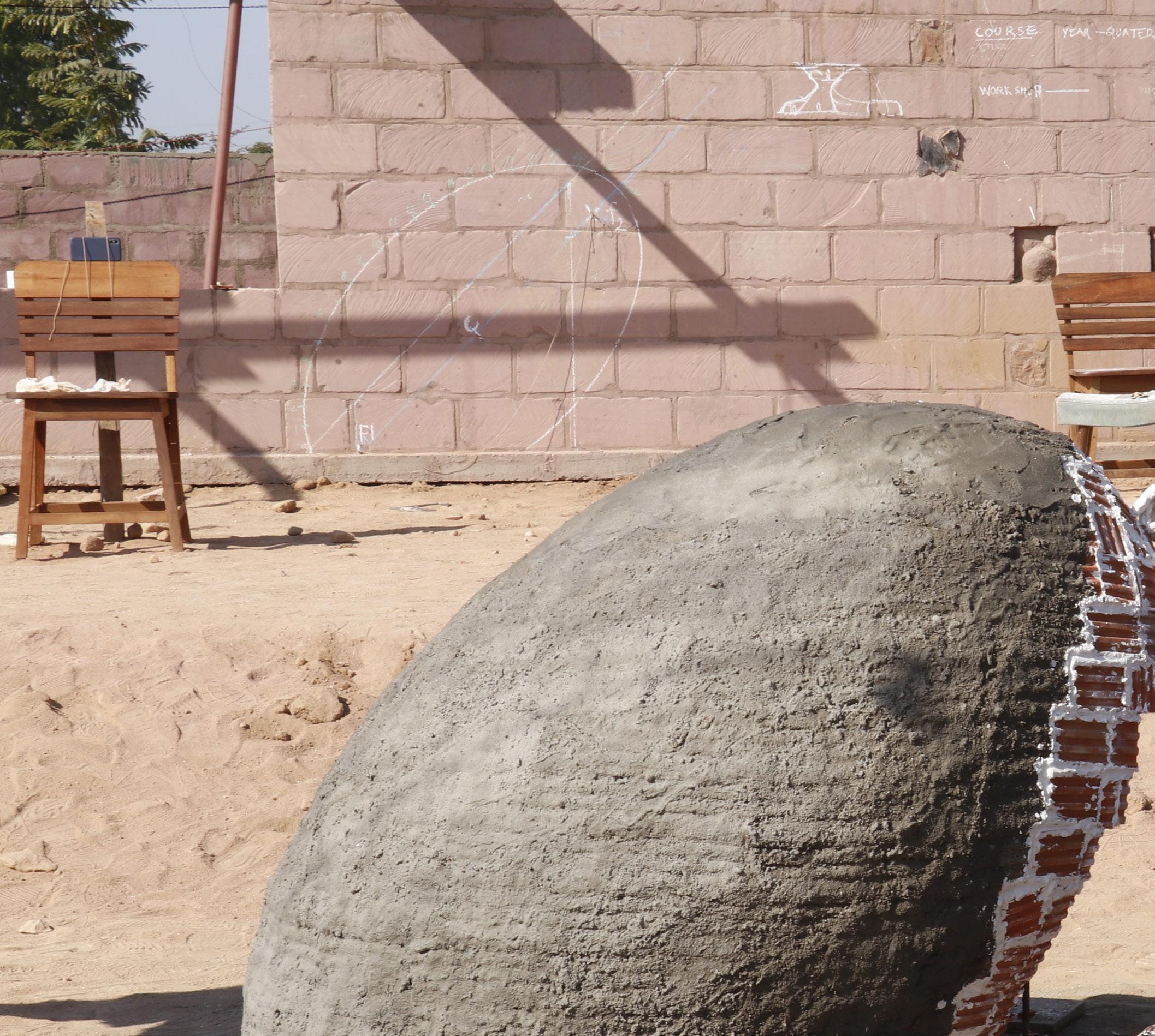
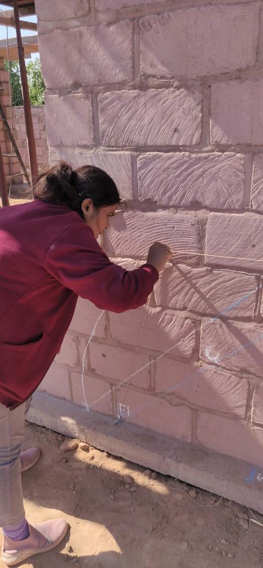
To construct the ellipsoid form, the placement of two foci points is very important. The first step is to mark those foci on the site using a metal rod or wooden stick. As the form is tilted, one of the foci points is higher than the other. These points are marked with the help of measurement tapes. For understanding the form and measuring the distance and height of the two foci, a full-scale geometry is drawn on the wall. Based on the dimensions, a string is tied on both the points such that the length of the string is equal to the focus of the ellipse. This string acts as a guide for constructing the ellipsoid form. The guide helps in generating accurate curvature and angle of tilt for the shape. There was a gradual change in the angle of tiles to attain the curvature of the form. The tiles are laid using PoP slurry to make the layers.
The guides and references for generating the shape play a very important role in the stability of form. That decides the structural strength. There are chances of the structure collapsing as a brittle failure if the structure is deformed. The ellipsoid collapsed as a result of such a brittle failure. While applying the first layer of plaster, the tiles couldn’t take the force at which the plaster was applied. Also one of the reasons in the form getting collapsed was the watery consistency of cement plaster. The excess of water in cement plaster weakened the bond of PoP. Hence it is very important for this construction technique to have accuracy and precision in everything.
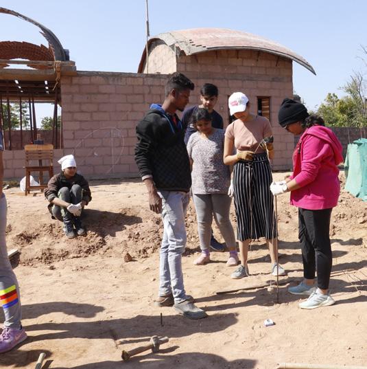
Fig 130. Fixing the vertical guide
9/26/2020 Fig 132. Making base
_MG_5839.CR2 9/26/2020 Fig 131. Drawing full scale
_MG_6143.CR2
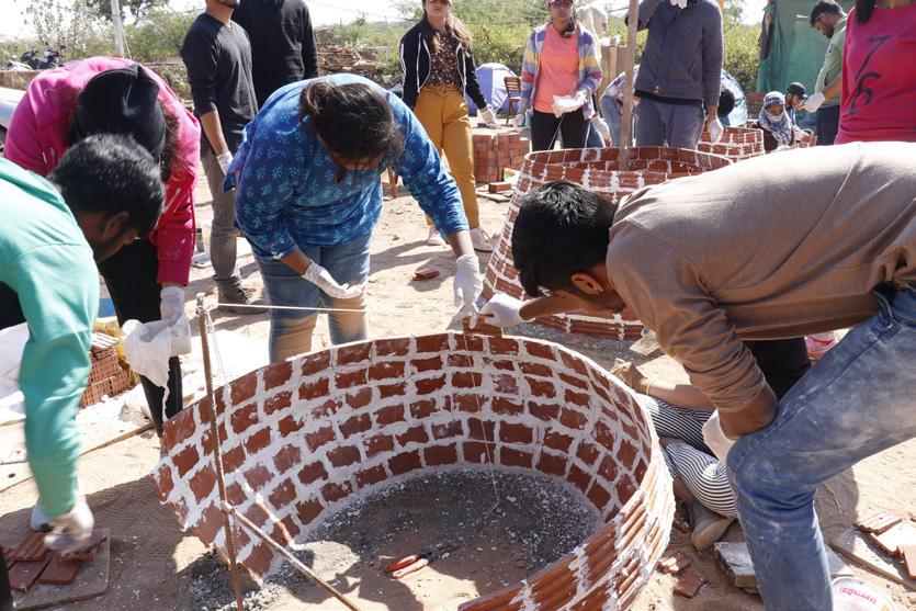
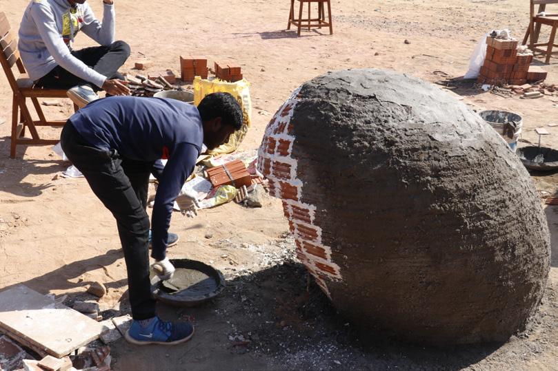
Fig 133. Using guide for tile Fig 134. First layer of plaster
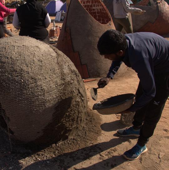
Fig 135. Second layer of plaster Fig 136. Collapsed structure


Fig 137. Brittle failure of form
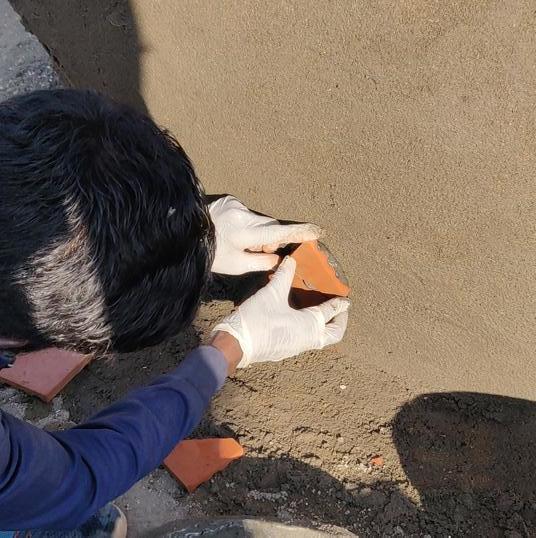

Fig 138. Tile cladding on form Fig 139. Final layer of cladding Fig 140. Finished ellipsoid form

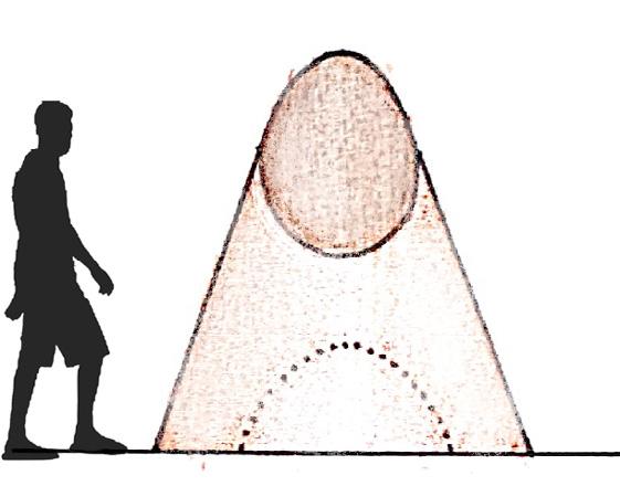
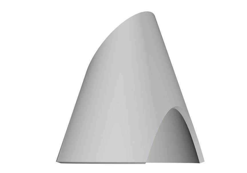
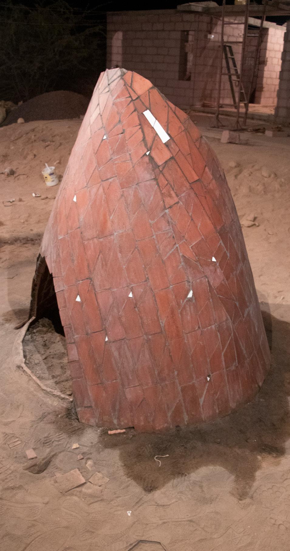
Cone
Cone is a solid or a hollow surface with a circular base that tapers on the top. The cone can be made by having a center of the circle and giving a definite height. Various shapes can be produced by cutting the cone at different angles. Shapes such as hyperbola, parabola, circle, and ellipse are formed by cutting the cone. Thus, the form design includes cutting of cone to explore the opening forming hyperbola and ellipse. The guide in this design is placed in the center to attain the height of the cone.
Photo Credit: Gagan Prajapati

Conceptual Sketches
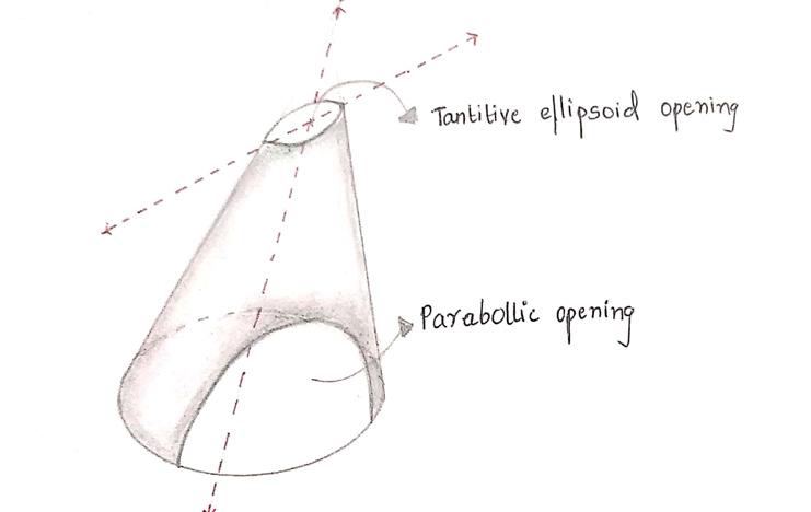
Fig 141. The initial idea for designing this object was to explore various shapes formed by cutting the object. The shape was sliced using a vertical plane to form a parabolic curved opening. It was noticed that when a tilted plane is used to cut the cone, an ellipsoidal curved opening is attained.

Fig 143. Later both the voids were generated by using tilted planes at different angles.
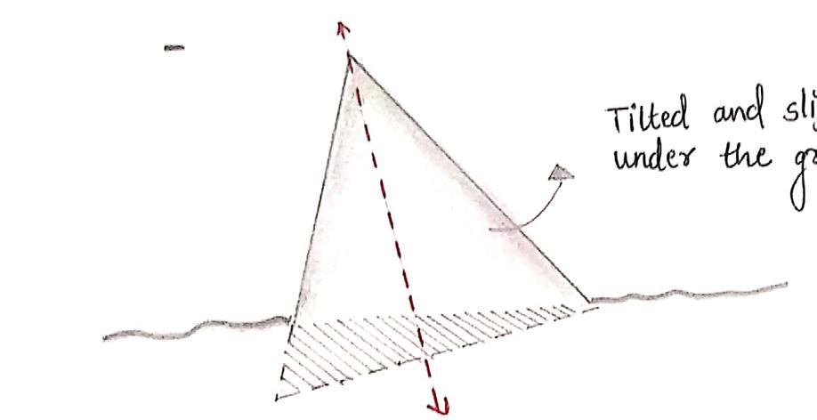
Fig 142. After cutting the object with a tilted plane, the form was also tilted to explore. But because the form was becoming less stable to be constructed with this material, the form was kept with a circular base.
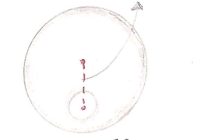
Fig 144. Looking at the object from the top, it can be seen that the opening was shifted off-center to attain the elliptical curved opening.
Fig 145. Finally, the radius of the base has arrived at 600mm and the total height of the cone was decided 2100mm based on the availability of tiles.
Fig 146. The above diagram represents the cut-outs using a vertical plane and a tilted plane. This gave two different kinds of curves namely parabolic and elliptical.
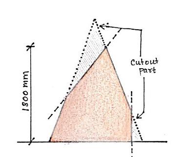
Fig 147. The height of the form concerning humans is higher than the human eye level. The openings are placed on opposite sides on the top and bottom.
Sketches & Calculation
Radius of Cone (r) = 600 mm Height of Cone (h) = 2100 mm Lateral Height of Cone (l) = 2184 mm
Tile dimensions = 230 mm x 75 mm x 15 mm Surface Area of Tile = 230 x 75 = 17250 mm2
No. of Tiles used per form = 420 tiles No. of Tiles used on each side = 210 tiles
Surface Area of Tiles on each side = 17250 x 200 = 36,22,500 mm2
Surface Area of Cone = πrl = 3.14 x 600 x 2184 = 41,14,656 mm2
Surface Area of Form = Surface Area of Tiles on Each side = 36,22,500 mm2
Area of Cut out on Form = S.A. of Cone – S.A. of Form = 4114656 – 3622500 = 4,92,156 mm2
Final Drawings
1120 mm
Fig 148. Plan of cone
Fig 149. Section of cone Fig 150. Exploded view of cone
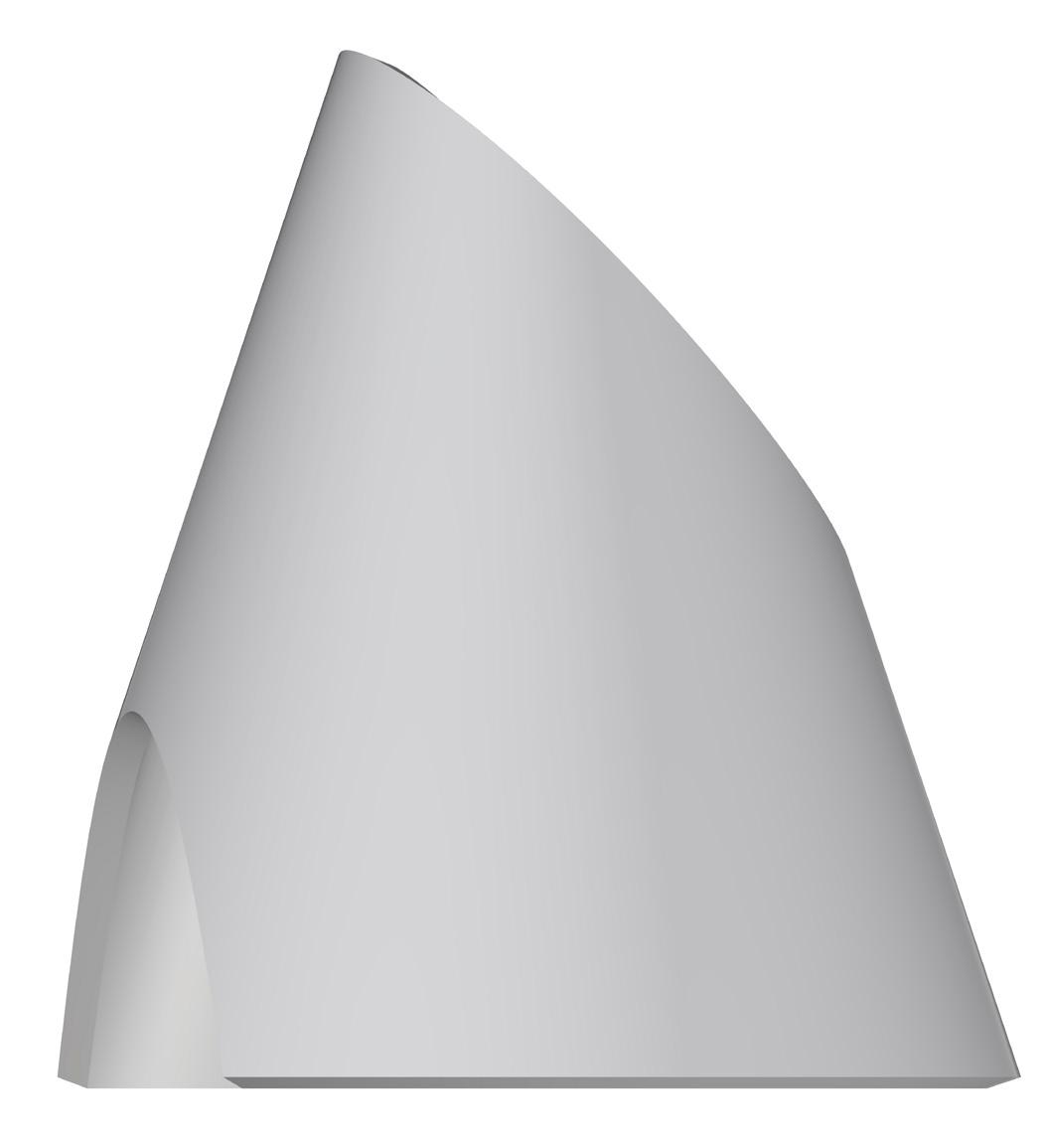
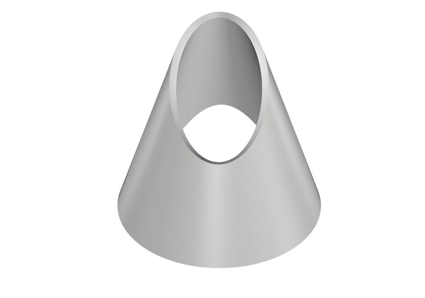
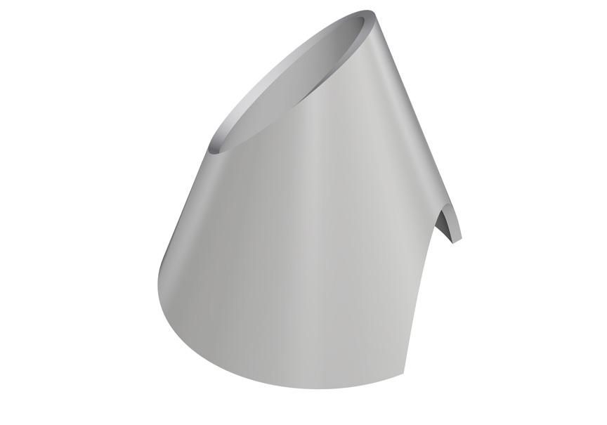
Fig 151. Elevation of cone Fig 152. 3D views of cone
To construct a cone, the circular base of the form is marked as per the radius. Once the circle is marked, the guiding stick or rod is fixed in the ground that is equal to the overall height of the form. A string or a thread is then tied on the top of the rod that acts as a guide for constructing the tile layers. The length of the string should be equal to the length of the cone. Instead of one, there can be two or more such strings so that many people can work simultaneously. It is to be noted here that the guide is always kept towards the outside because as the number of tile layers keeps on increasing, the guide cannot be used from the inside. Then after every layer, the decreasing radius is marked that acts as a guide for the tile layers.
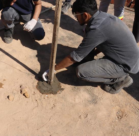
Fig 153. Fixing the vertical guide
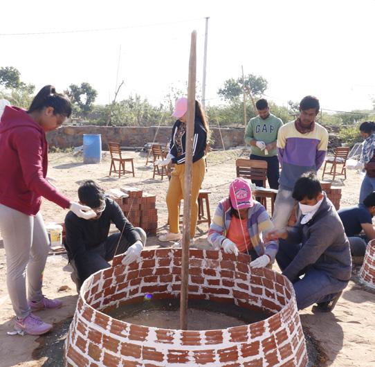
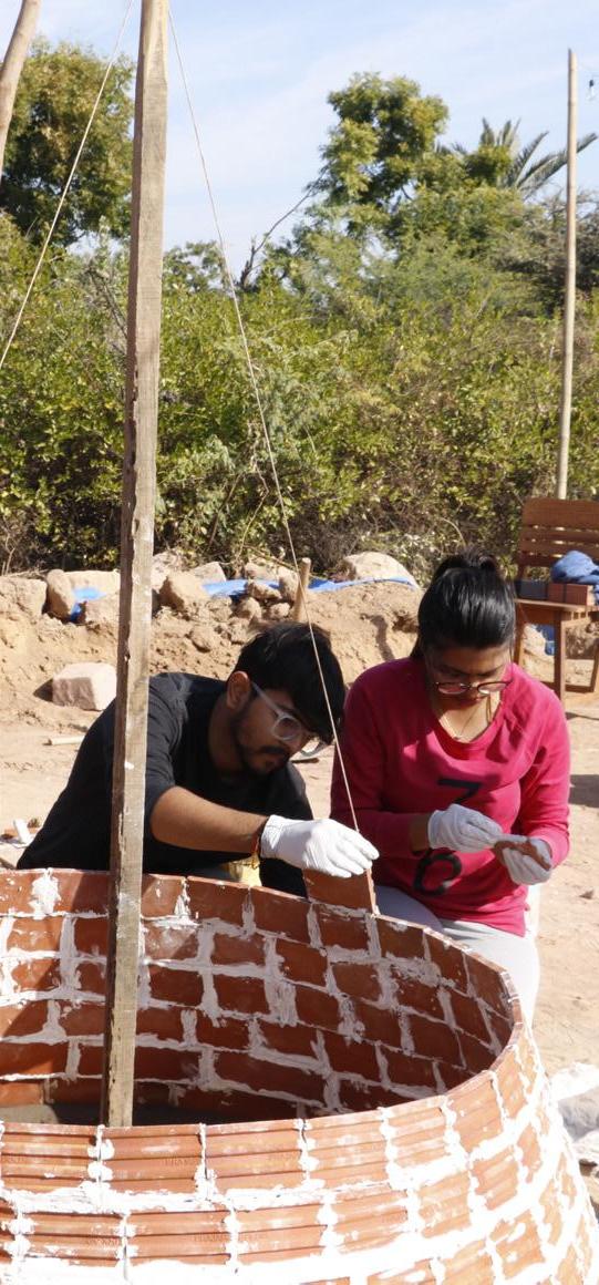
Fig 155. First layer of tile Fig 154. Measuring as per guide
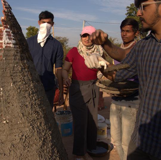

Fig 156. First layer of plaster Fig 157. Wrapping chicken mesh

Fig 158. Second layer of plaster _MG_6269.CR2
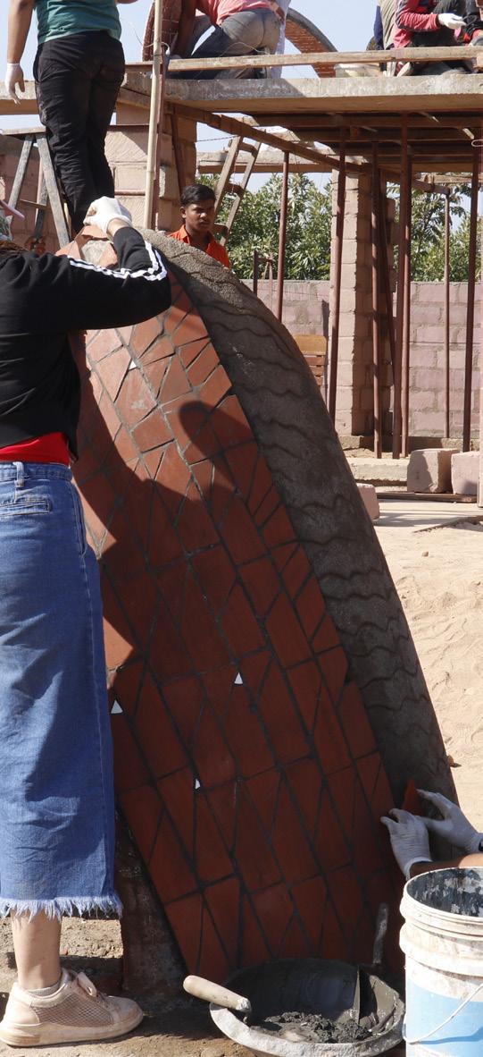
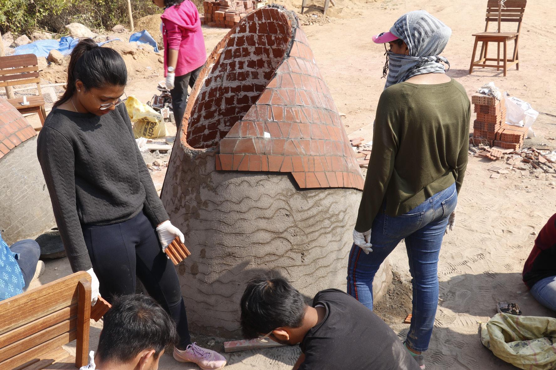
Fig 159. Cladding of tile Fig 160. Final layer of cladding Fig 161. Finished conical form
Project By: Studio Dot Project By: Studio Dot