

The Construction of Destiny Bridge and the New Kingsway


The £150m Cross Tay Link Road project was approved by Perth & Kinross Council in June 2016.
The project centres around Destiny Bridge – a threespan structure crossing over the River Tay; and the New Kingsway – a six-kilometre stretch of new carriageway linking the A9 to the A93 and A94. It also includes two kilometres of realigned dual carriageway on the A9 just north of Inveralmond Roundabout.
The project’s key priority is focused on improving air quality and reducing congestion in the centre of Perth, by providing a new transport infrastructure that offers an alternative to driving through the city itself.
Transforming travel across the region, Destiny Bridge and the New Kingsway play a significant role in unlocking the economic potential of Perth by opening areas for future development and, in turn, maximising inward investment opportunities. The project also improves Perth’s already excellent interface with the trunk road network, building on its enviable location and connectivity in the heart of Scotland.
To this end, the Scottish Government awarded a £40m funding contribution to Perth & Kinross Council, with the balance coming from the local authority itself.
During construction the project helped our communities and local businesses, created job opportunities and built new talent to tackle local skills shortages, helped community and legacy projects like Denmarkfield Allotments and Community Orchards, and developed a new active travel path network and new community artwork project, all of which will now bring enjoyment and health benefits for many years to come.

Jillian Ferguson Roads Infrastructure Manager, PKC
“The project’s key priority is focused on improving air quality and reducing congestion in the centre of Perth, by providing a new transport infrastructure that offers an alternative to driving through the city itself. I look forward to seeing this in action and to everyone reaping the benefits thereafter.”
Councillor Grant Laing Leader of Perth & Kinross Council


Driving Forward Perth’s Ambitious Future
The £150m Cross Tay Link Road (CTLR) project was approved by Perth & Kinross Council in June 2016 to address the long-term transportation needs of the area.
As phase two of the ambitious Perth Transport Futures programme, the CTLR project provides a solution to the longstanding concerns about air quality in Perth, by diverting traffic away from the most congested and polluted parts of the city centre.
The project also enables new, planned and committed development as set out in the Local Development Plan, meeting the requirements of TAYplan and unlocking the sustainable growth of the Perth area.
The CTLR project centres around the construction of Destiny Bridge – a three-span bridge over the River Tay – and the New Kingsway, a six-kilometre stretch of new carriageway linking the A9 and the A93 to Blairgowrie and the A94. It also includes the construction of two kilometres of realigned dual carriageway of the A9 just north of the Inveralmond Roundabout.
Funded by Perth & Kinross Council and the Scottish Government via Transport Scotland, the CTLR project has been heralded as playing a vital role in the future of Perth and Kinross – both economically and environmentally.
Following a robust procurement process, in August 2021 engineering and construction group BAM UK & Ireland were awarded the contract for the detailed design and advance works of the project. The second part of the contract for construction was awarded in September 2022.


Design & Concept
In 2017 Perth & Kinross Council appointed Sweco, one of Europe’s leading engineering, environment and regulatory consultancies, to design the preferred alignment of the new road linking the A9 north of Inveralmond to the A93 and then the A94 north of Scone.
This included preparing the planning application and identifying key priorities around budget, added value and decarbonising the build through the initial design and procurement process.
This innovative approach to carbon savings has now been embedded in the British Standards Institution’s
recently updated PAS 2080:2023 Carbon Management in Buildings and Infrastructure guideline document, as an example of best practice for procurement.
In addition, engineers from both Perth & Kinross Council and Sweco were awarded the accolade of Institution of Civil Engineers (ICE) Carbon Champions.
Various concepts were proposed and discussed for the bridge itself, but it was the cost and carbon efficiencies in the chosen design that presented the most compelling case.

Cost and Construction Efficiencies
As part of the design and planning process, Perth & Kinross Council decided on a three-span, low-level bridge with the western back span over the Perth to Inverness-Highland railway line.
Cost and environmental risks increase greatly when waterbased construction is involved, but this design utilised piers outside the normal extents of the River Tay (except in the eastern floodplain), making it the most economical choice in terms of capital costs, as well as offering ease of construction, protection of the River Tay, and efficiencies for future maintenance.
On contract award BAM UK & Ireland appointed design consultants Arup/Fairhurst (as a joint venture) to undertake the detailed design of the project, including Destiny Bridge.
Following consultation with statutory consultees and user groups, including Network Rail, SEPA and Tay District Salmon Fisheries Board, planning consent for the scheme was granted in October 2020.
“The main aim during the design, procurement and build process was to deliver the project as close to a net zero carbon development as possible, underscoring Perth’s intention to become one of the most sustainable small cities in Europe.”
Jillian Ferguson, Roads Infrastructure Manager, PKC
Design Engineering The Wider Scheme
Arup Fairhust Joint Venture were responsible for value engineering, detailed design and construction supervision of the scheme on behalf of BAM UK and Ireland.
To accommodate the new Destiny Bridge the new Kingsway Road was designed to connect the A9, Stormontfield Road, A93 and A94. The design of this new section of road included a range of earthwork design techniques to prepare the ground; roadside drainage and basins; a new green bridge; culverts; traffic signs; safety barriers; street lighting and landscaping.
A 2km section of the existing A9 trunk road was realigned. The delivery of this crucial part of the project infrastructure required a close working relationship between PKC,
Transport Scotland, BAM and the design team to ensure the design met the requirement of all stakeholders and complied with standards.
Innovative 3-dimensional design methods were adopted from the start of the detailed design. This allowed the team to co-ordinate infrastructure components to ensure all the designed elements avoided construction clashes whilst on site.
These models were used during the construction stage to achieve accurate positioning of vital components, generating construction efficiencies and improving delivery time.


Design | Balanced Cantilever Challenges
Destiny Bridge consists of a three-span post-tensioned concrete box girder deck supported on reinforced concrete abutments, piers and foundations. The deck sits on bearings which allow it to slide and rotate relative to a fixed point at the east pier where horizontal loads such as vehicle braking are resisted.
Post-tensioning is a technique used to achieve a stronger, more durable structure. A network of ducts are cast into each concrete segment through which high-strength steel tendons are then placed. Once the concrete has reached sufficient strength the tendons are tensioned using hydraulic jacks.
These tension forces pull the segments together, adding a compression to the concrete and enhancing its strength and stiffness. The internal stresses from the post-tensioning counteract the external stresses from loads, reducing structural deformation and concrete cracking. In addition to the tendons, the concrete is also reinforced with steel bars (reinforcement) which are not post-tensioned (stressed).

In order to allow construction over the Tay and the railway the bridge was built using the balanced cantilever method of construction with the deck built symmetrically and sequentially out from the piers. This method greatly influenced its design, with some of the most onerous load scenarios occurring during it. Segments were effectively hung together through the stressing of tendons located in the top slab of the box, known as cantilever tendons. In latter stages of construction tendons in the bottom slab of the box were tensioned, known as continuity tendons. These tendons help reduce deflections and cracking and improve the overall distribution of forces.
With hundreds of load scenarios to consider, a complex geometry and thousands of components to the bridge the engineers drew upon extensive use of coding, visual scripting and computer modelling to optimise the design. All tendons and reinforcing steel were modelled in 3d. This simulation approach reduced the risk of clashes between components and the potential for on-site changes during construction.


Challenges Resolved The Railway and Cofferdam
A project of this size and scale is never without challenges, and for the Destiny Bridge build, one of the key considerations was the Perth to Inverness-Highland railway line that runs parallel to the River Tay.
Looking forward, it is highly likely that this important network line will become electrified, necessitating a 6m clear height between bridge and line. Subsequently, this created a pinch point on the west side of the bridge.
Working in consultation with Network Rail throughout the initial and detailed design processes Sweco, BAM UK &

Ireland and their designers Arup/Fairhurst adapted initial designs by lowering the east pier, and easing it into the existing land levels – this reduced material volumes and the carbon impact.
As a result the east pier moved closer to the water, which required an additional layer of construction in the shape of a cofferdam. The fabrication of this 16m x 16m boxlike structure is arrived at by driving 10m long steel sheets into the soil below water level and sealing them to allow a dry area for the piling and foundation work to take place.


The cofferdam
Piling Building a Strong Foundation
As with many Scottish glens, the ground around the River Tay is made up largely of soft silts and clay. Unsuitable as a stable base for laying foundations, a process called piling takes place, which in the case of Destiny Bridge, saw engineers drill down to rock some 55m below ground level on both east and west sides.
Installing 25 piles at each pier, with each measuring 1.0m in diameter and between 50m and 55m in length, the piling process involved the placing of reinforcing steel and the pouring of concrete into the drilled holes. Separately, 20 piles were also drilled for the west abutment, and 15 piles were drilled for the east abutment. These measured 1.35m in diameter.
The concrete piles were then cut down to offer an even surface for the placement of a 2.5m thick reinforced concrete pile cap. Once complete, the piling process formed the base of the east and west piers of the bridge.
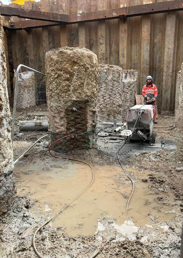

“Due to the complexity (diameter and depth) of the piles, we encountered significant challenges which resulted in piling operations taking longer than originally anticipated.
This was overcome by procuring additional specialist equipment and extending working hours. In total, the critical piling operation for the pier foundations was completed in just under nine months.”
Derek Walsh Contracts Manager, BAM UK & Ireland
Substructure
Forming the Basis of a Bridge
The substructure of any bridge forms the all-important support for the main bridge superstructure. It is the connection between the superstructure (bridge deck) and the foundations that facilitates load transfer.
On Destiny Bridge, the substructure includes the east and west piers which sit on the banks of the river, and the east and west abutments, which sit further back on the approach to the bridge and transfer the weight of the structure into the foundations.
Made of reinforced concrete, the piers of Destiny Bridge are up to 8.9m high, and 6.3m wide, and the abutments are up to 16.4m high and 15.83m wide.


“Integral to the structure construction was the design, fabrication and installation of temporary props located at each pier which consist of heavy-duty steel circular hollow sections.
They were installed as part of the sub-structure construction albeit only becoming operational once the deck segments were commenced.”
David Kilburn Regional Engineering Manager BAM UK & Ireland
Hammerheads Building Out
As the first section of the superstructure, the hammerheads are the all-important starting blocks of the bridge deck itself, and act as the centrepoint for the form traveller and deck segment construction. All bridges are designed to allow thermal movement to take place. This natural process occurs during temperature changes, when concrete is heated and expands or cooled and contracts.
To allow this to happen safely, bearings are installed on top of the piers and abutments with Teflon-like surfaces to allow the bridge to move freely around a fixed point which is the east pier south bearing. The bearings are also there to reduce the load effects into the piers.
During the construction process, the hammerhead allows the growing superstructure to move safely across the substructure and transmits the variable loads of the build into the piers. To support the out of balance forces, temporary props are used to stabilise the hammerhead and are removed only once the bridge is complete.

“Arguably, this element of the bridge construction was the most challenging, largely due to the severe weather encountered during construction of the hammerheads. The construction team endured flood events and freezing temperatures throughout the winter of 2023.
“The hammerheads’ formwork was temporarily supported to ensure the concrete elements gained sufficient strength to facilitate post tension stressing and removal of the temporary formwork supports. There was 890m3 and 162T of steel in each hammerhead which were up to 17.5m from ground level.”
Derek Walsh Contracts Manager BAM UK & Ireland


The Superstructure Takes Shape Form Traveller and Deck Segments
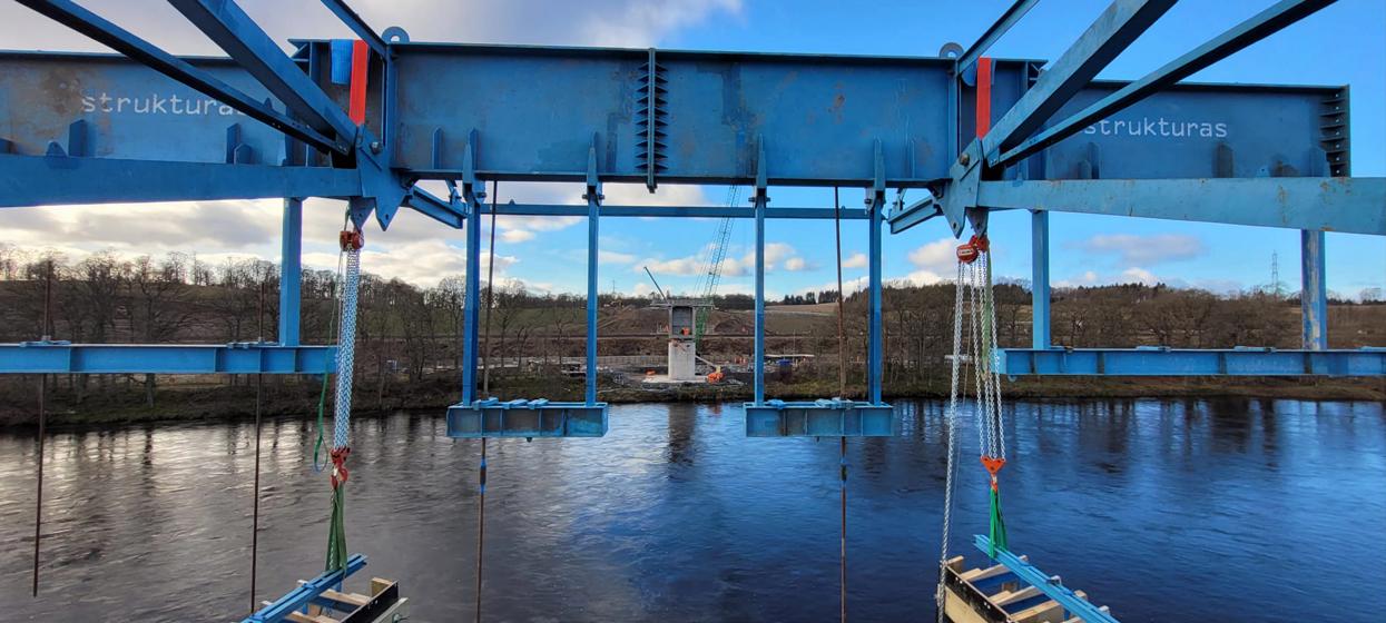
Made up of over 3,850 pieces, construction of the two Balanced Cantilever Form Travellers around the hammerhead denoted an important stage in the project –the commencement of the deck segment build for Destiny Bridge.
The construction of the 56 individual deck segments, which typically varied between 4.6m and 5.65m, and were fabricated from reinforcement steel, high-strength concrete, and post-tensioning cables, followed a careful sequence, alternating between either side of each pier, to maintain a perfect balance.


During this process, both Balanced Cantilever Form Travellers moved along the superstructure, offering local people a striking, visual representation of the progress being made.
Each form traveller weighed approximately 123T and was supported by a superstructure frame located back on the bridge deck. During each deck segment concrete pour, an additional 195T of weight was supported by each form traveller.
Working with Experts Global and Local Knowledge
Calling on global expertise, the form traveller system on Destiny Bridge was supplied by specialist Norwegian contractor, Strukturas, and construction of the main deck segments was carried out by Carrapatelo Construction Engineering Ltd from Portugal, who were supported by local resources to assist with the works.
In total over 5,000m3 of concrete was cast into the deck segment utilising close to 900T of steel reinforcement. In addition, approximately 320T of stressing strand and 142,000kg of grout were used in the construction of the bridge which was supplied and incorporated into the bridge by stressing specialist, VSL.


“The form traveller system is widely used in the construction of balanced cantilever structures throughout the Civil Engineering industry. Key to the success of their use is careful and methodical assembly and installation.
“Once in place, the use and operation of it is a repetitive process, with a typical segment construction cycle taking approximately one week. Having skilled and experienced specialists as part of the team was critical to the success of the project.”
Derek Walsh Contracts Manager BAM UK & Ireland

Stitch Process
Tying Together the Superstructure
As the final stage in the main superstructure build, the three-stitch process on Destiny Bridge followed a precise construction sequence to ensure balance of load throughout the process.
The first stitch, segment EP-SS14, is located on the east end of the structure, and was poured on 23rd July 2024. Once complete, the east section of the structure was stressed using post-tensioning cables, before moving onto the internal kentledge (an in-situ block of concrete used as permanent ballast or counterweight).
This pour facilitated the installation of an alignment device at the bridge mid-span, ensuring both approach decks were at the same level before completing the second stitch (WP-MS15) on 19th August 2024.
The third and final stitch, segment WP-SS15, located on the west end of the structure, followed a similar process in that the main deck continuity tendons were stressed; however, at this stage the western pier temporary prop was removed using hydraulic jacks before the alignment device was set in place.
The third stitch was poured on 16th September 2024, joining the bridge and heralding the completion of the superstructure’s main construction.

“The completion of the final stitch marked a significant milestone for the project which was testament to the hard work and dedication of the bridge construction team. By achieving this in September 2024 it ensured that the project would be completed for early spring 2025.”
Derek Walsh Contracts Manager BAM UK & Ireland
Finishing Futureproofing the Infrastructure
Once the main construction is complete, the finishing process can start. Although it looks to the untrained eye to be ready, an additional four-month period is required for the final works to take place.
The deck waterproofing defends against the Scottish weather and protects the structure from road salts, car fumes and other spillages.
Barriers come next, with two different types used. The N2 barriers run alongside the majority of the bridge, with H4A barriers allowing for higher protection above the Perth to Inverness-Highland railway line.
Kerb drainage units are installed next, which collect water from across the structure, and convey it to the lower, east side of the bridge and into the drainage network.
Finally, cycle paths, pavement, line marking and road studs are added to provide the last elements of Destiny Bridge.
“The completed bridge is a concrete box, with cantilever wings. Access through stairs and walkways at both east and west abutments, stretches through the entire length of the bridge to permit routine inspections of the internal structure, and to provide access to the bearings.”
Paul Johnston, Sweco


Environment and Ecology
Greener Construction


Immediately following award of the Detailed Design and Construction Contract, BAM UK & Ireland engaged with SEPA, NatureScot, Perth and Kinross (Planning) and other regulatory bodies to ensure the carbon efficiencies and ecological focus established at procurement stage would continue throughout the life of the project.
Initially, elements of the specimen design were revisited to realise value engineering opportunities wherever possible. Of note, the redesign of the spans and cross section of Destiny Bridge led to the elimination of in-river working at the west pier, and a reduction in construction materials required for the deck. Successful refinement of culverts was also achieved through this early consultation.

Construction of the east pier cofferdam and associated in-river works posed significant environmental risk and had to be undertaken outwith seasonal constraints in consideration of migrating fish. Sharing the construction programme and methods with SEPA was key in ensuring compliance with consents, as well as agreeing measures to prevent pollution.
Alongside this, ecological surveys were undertaken in advance of construction to establish the baseline for ecological diversity. This allowed BAM UK & Ireland to develop live constraint maps and to identify any additional consent required. Continuous liaison with SEPA, NatureScot and others, ensured development of species protection plans in accordance with current guidelines.
“During the project build, an independent site Environmental and Ecological Clerk of Works (ECoW) was engaged to report to PKC as both the client and the planning authority. BAM also employed a second onsite ECoW, who was supported by an Environmental Manager to ensure construction progressed in accordance with all consents. Regular interface meetings with key regulatory bodies yielded a positive culture and allowed for ongoing advice and collaboration.”
John Slaven Senior Project Manager,
BAM UK & Ireland

The Green Bridge
The Green Bridge at Highfield, which forms part of the overall scheme, is an outstanding example of this type of structure.
Careful consideration during the design process was given to ensuring the structure blended into the surrounding beautiful landscape, whilst also serving its function to provide connectivity for people and animals and enhancing biodiversity. The mural and the living bench (right) were undertaken by Scottish artists as part of the Community Artwork project for the whole scheme.


“This structure required careful design considerations. The foundations had to be designed to accommodate large forces caused by the low slender profile of the arch. The buried nature of the structure also allowed the landscape design to traverse the road below, creating a fantastic ecological corridor and an asset for the local communities.”
Carol Geddes
Project Manager, Arup Fairhurst Joint Venture
A9 and Link Road
By May 2022, the design was sufficiently advanced to enable earthworks to begin on the A9 and the new link road sites. Throughout that summer and into autumn, these bulk earthworks were completed which allowed the installation of 26km of drainage across the project site.
It was impossible to carry out the realignment of a major road network without disruption and between April and August 2023 it was necessary to introduce two separate contraflow traffic management systems to complete the works on the A9.
A total of 12 weeks of intense work saw the new A9 realignment open to the public, and both northbound and southbound carriageways were in use as Perth welcomed hundreds of cyclists in the Gran Fondo World Championships to the area.
This project milestone opened the next phase of significant works which included connectivity between the A9 to the link road – which by then had been named the New Kingsway by local schoolchildren.
By December of 2023, all junctions on the New Kingsway were constructed.
Over 2024 and into early 2025, the Park & Choose area and active travel route linking the project site to the existing Almond core path were completed, and landscaping, street furniture, street lighting, signage, and signalling were installed along the full route.
Finishing works on the New Kingsway came to an end in early 2025.


The Wetlands
An important feature on the New Kingsway route is the new wetlands area which is located slightly west of Stormontfield roundabout. The combined cycleway and walkway route meanders to the south of the wetlands allowing the public to experience nature up close.
The primary functions of the wetlands are to provide a habitat for wildlife while also containing and treating surface water from the new road infrastructure.
The addition of a bird hide gives birdwatching enthusiasts a good vantage point and shelter during unseasonal weather. Aquatic plants and shallow pools enhance the wetlands and attract other wildlife species to the area also.

“It was important for Perth & Kinross Council to involve the community in the project where possible. One example of this was giving local children the opportunity to work with artists engaged on the project to design and create legacy artwork pieces for people to enjoy.”
Sarah Gardner Project Officer, Perth & Kinross Council

Community Benefits
Using public spending to make Perth and Kinross a better place to live, work and do business has been an integral part of the Cross Tay Link Road project since its inception.
From visits to schools with the Bridge Building Challenge, to summer-long placements for university students, project open days, charitable fundraising, path and garden clearances, and school playground upgrades, the work carried out has been both diverse and meaningful.
Importantly, the project has both assisted and generated several legacy projects including the Denmarkfield Allotments and Community Orchards, and the new active travel path network and community artwork project, all of which will bring enjoyment and health benefits for many years to come.
Over £15,000 has been raised for local charities, and targets set for work experience, skills development, and engagement with educational institutions, have all been exceeded.


Charity Fundraising Breakdown

The Community Artwork Project

One of the largest and most significant community benefits, is the community artwork project. Following a series of community engagement events in 2023, the brief for the artwork project was developed by Nichol Wheatley, Artist Curator, identifying eleven possible locations and themes ranging from biodiversity to active travel, history and local geography.
From here, four projects were selected and artists appointed to create the works which are located along the active travel path network.
The Living Bench, created by artist Louise McVey, has been inspired by its location on the Green Bridge. The souterrain project, led by artist Kate Robinson, represents the excavation of a souterrain during the archaeological dig (bottom left) at the commencement of the CTLR project.

The wetlands project, led by artist Louise Kirby, involved workshops with local families and local nursery, Apple Tree Nursery. The wetlands also includes a bird hide which was built for the project by Scone Airport Men’s Shed.
Two mural projects by Shona Hardie have added a vibrant splash of colour to the underside of the Green Bridge (above, bottom right) and the portal which provides local access to Denmarkfield and the active travel path network.
There is also a stone carved bench by artist Lucinda Wilkinson on the active travel path at Denmarkfield.

Park & Choose and Active Travel
A9294:NewKingsway
As well as improving travel around the region, the project has also facilitated the creation of 12 kilometres of new and upgraded paths, stretching from the north of Scone, along the New Kingsway and over Destiny Bridge, and serving as a link to Highfield woods.
Highlights along the path include the Green Bridge and Living Bench, the wetlands bird hide and picnic area, and the souterrain (underground chamber) which was excavated during the archaeological investigations prior to the initial earthworks and rebuilt as part of the project.
The active travel path network connects via a central hub at the new Park & Choose, which is located on the old A9. As well as parking, the hub will include a picnic area with wheelchair accessible benches, cycle shelters and EV charging points.
“Perth & Kinross Council is committed to ensuring that the Cross Tay Link Road project benefits everyone in the community and we’re pleased to be making it easier than ever before for local people and visitors to get out and enjoy our area.”
Councillor Grant Laing Leader of Perth & Kinross Council
Luncarty
Visualising the Scale
Volume of concrete cast into the deck segment

= 5 million litres, or 2 Olympic swimming pools!
900 tonnes of steel reinforcement
The deck concrete alone used There were Plus = the weight of 6 blue whales! = a family of 20 elephants! = 25 double decker buses!
142 tonnes of grout used in the bridge
320 tonnes of stressing strands

The Cross Tay Link Road Project, including Destiny Bridge and the New Kingsway, is the largest infrastructure project ever undertaken by Perth & Kinross Council.
As phase two of the Perth Transport Futures Project, it plays a significant role in improving the long-term transportation needs of the area, while promoting economic growth and addressing issues of congestion and pollution within Perth city centre.