17 minute read
New Basegrade Stabilisation Technology Resolves Thin Pavement Issues in Redland City
Scott Young BE (Hons), MPavtTech, RPEng (Civil), RPEQ
Sealed flexible pavements typically consist of a wearing surface, a base layer and a subbase layer to protect the subgrade from damage caused by traffic loads over time. Local government urban roads in Australia often only have a base layer sitting directly on the subgrade. When the thickness of the existing granular base layer is deemed too thin to satisfy rehabilitation design requirements, the base and subgrade layers can be insitu stabilised simultaneously with an appropriate binding agent. This is termed ‘Basegrade Stabilisation’ (Young, 2020).
Experimental research completed in 2020 developed a mix design procedure for basegrade stabilisation to allow practitioners to confidently evaluate an existing pavement structure and select a trial mix design for laboratory testing. This paper explores the background of basegrade stabilisation, the subsequent development of a new mix design procedure and how it can apply to a local council asset management plan. A case study from Redland City also demonstrates the effectiveness of basegrade stabilisation.
INTRODUCTION
The typical pavement structure often designed in new flexible pavements consists of multiple pavement layers that absorb the traffic induced loads to protect the subgrade from permanent deformation. This typical pavement structure is illustrated in Figure 1.
Wearing Surface
Base
Subbase Typical Pavement Structure
Subgrade
Figure 1. Typical Flexible Pavement Structure (Young, 2020).
Local government roads however are not always this fortunate, and thin granular layers (or just a single layer) commonly exist between a bituminous wearing course and the subgrade. When these common pavement structures are identified for rehabilitation, the absence of a subbase layer results in the base layer having inadequate thickness to recycle using insitu stabilisation based on the requirements to satisfy structural design requirements (e.g. a 20year design life).
Wearing Surface
Base Common Pavement Structure
Subgrade
Figure 2. Common Flexible Pavement Structure in Lightly Trafficked Roads (Young, 2020).
This challenge however can be overcome by adopting the process of basegrade stabilisation in lieu of other more expensive renewal treatments, such as complete removal of all pavement materials and replacement with imported quarried materials.
BASEGRADE STABILISATION DEFINED
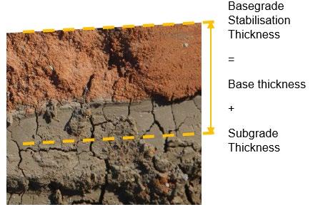
Basegrade stabilisation (Young, 2020) is the process of insitu stabilising existing granular pavement materials that are mixed with subgrade materials with a suitable binder to improve the engineering properties of the combined layers. Basegrade stabilisation occurs when the existing pavement gravels comprising a base course (and/ or subbase course) are not thick enough and a deliberate decision is made to incorporate subgrade materials into the granular materials to satisfy the required depth of stabilisation (refer Figure 3).
Wearing Surface
Base
Subgrade Subgrade Required Depth of Stabilisation
Figure 3. The ‘Basegrade Stabilisation’ Concept (Young, 2020).
Basegrade stabilisation as a process is not a new concept and has been used widely in Australia,
mostly in the local government road network where thin pavements overlying subgrade materials exist and were treated simultaneously through insitu stabilisation. However, there is no documented protocol to enable mix design optimisation based on the blended properties of the pavement and subgrade materials.
In 2001, a survey by Monash University distributed to more than 450 local councils across Australia was undertaken to assess multiple aspects about the use, performance and hindering aspects of pavement stabilisation (Young, 2020). Even after earlier publications in the preceding decades emphasized the need to carry out mix designs for proposed stabilisation works, the survey revealed a resounding lack of mix design procedures were readily available for engineers to follow. This form of multi-layer insitu stabilisation and the gap in mix design protocol formed the basis of the 2020 research undertaken by the author which is subsequently examined in this paper with applications for implementation into local government asset management strategies.
APPLICATIONS FOR BASEGRADE STABILISATION
The predominant application for basegrade stabilisation in local government is existing roads that have inadequate granular thickness and have been evaluated through structural analysis as requiring a thicker treatment at the time of intervention. Figure 4 illustrates this where the design thickness exceeds the available thickness of existing pavement material.
Figure 4. Basegrade Stabilisation Composition (image ref: Young, 2020).
Therefore, when a site evaluation identifies the deficiency in existing pavement thickness, basegrade stabilisation can be considered. Since increases to existing pavements can occur in rural environments or locations where no level control exists, basegrade stabilisation solutions are more commonly suited to urban environments where kerb and channel structures inhibit increased levels.
This mix design procedure developed in the 2020 research will benefit local government engineers, consultants and geotechnical engineers across Australia by providing evidence that blending subgrade materials with pavement granular materials can achieve desired strength outcomes with the application of suitable mix design protocol and minimal variability in strength gains.
THE EXPERIMENTAL RESEARCH PROGRAM
The primary objective of the research work conducted in 2020 was, ‘To develop a mix design procedure for basegrade stabilisation treatments on local government pavement rehabilitation projects identified in lightly trafficked environments.’
The mix design procedure aimed to optimise the binder type, the binder application rate and the construction procedure based on the properties and proportion of subgrade materials proposed to be mixed into existing granular pavement materials using insitu stabilisation.
Nine pavement types were examined in the research. They comprised three subgrade materials of varying plasticity and subgrade proportions of 20%, 35% and 50%. Three binders were added to the nine pavement types at various application rates. They were: • Various lime/cement/flyash triple blends • 60/40 slag/lime blends • 70/30 cement/flyash blends after pre-treatment with 3% hydrated lime Unconfined compressive strength (UCS) testing was the principal test. The target strength was 1-2MPa which was based on the success of lightly bound materials used in local government in Australia for more than 50 years.
Selection of each subgrade source was intended to provide distinct variations in properties, particularly the consistency limits. The raw materials are illustrated in Figure 7.
Table 1 summarises the host material properties of the four individual materials, while Figure 8 illustrates the variation in linear shrinkage between each material type.
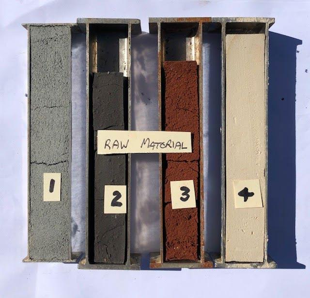
Figure 8. Linear Shrinkage: Raw Materials (Young, 2020).

Figure 7. Raw Materials (Young, 2020)
Raw Material # 1 2 3 4
Property
Liquid Limit (%)
Plastic Limit (%)
Type 2.3 Gravel Pittsworth Alluvial Redlands Silt Wallum Court Clay
19.6 82.4 65.4 38.8
17.6 33 37 24.6
Plasticity Index (%) 2.0
Linear Shrinkage (%) 1.4
Maximum Dry Density (t/m3) 2.18
Optimum Moisture Content (%) 8.5 49.4
21.4
1.34
29.5 28.4
16
1.35
38 14.2
3.4
1.68
21
4 Day Soaked CBR (%)
Swell (%) 70
0.0 1.5
0.8 2.5
0.3 8
1.9
Table 2 shows the characteristics of the blended basegrade materials developed for each of the nine trials used in the research.
Table 2. Blended Raw Material Characteristics: PT1-PT9 (Young, 2020)
Subgrade Material Pittsworth Alluvial Redlands Silt Wallum Court Clay
Pavement Type PT1 PT2 PT3 PT4 PT5 PT6 PT7 PT8 PT9
Gravel/Subgrade Proportions 80/20 65/35 50/50 80/20 65/35 50/50 80/20 65/35 50/50
Liquid Limit (%) 36.4 69.6 74.0 38.2 59.0 61.0 25.2 32.0 36.0
Plastic Limit (%) 15.6 31.0 32.8 16.4 28.8 30.2 16.4 23.0 21.4
Plasticity Index (%) 20.8 38.6 41.2 21.8 30.2 30.8 8.8 9.0 14.6
Linear Shrinkage (%) 6.0 13.2 16.6 10.0 10.0 12.0 3.4 6.6 6.6
Maximum Dry Density (t/m3) 2.00 1.85 1.76 2.05 1.89 1.82 2.10 2.07 1.96
Optimum Moisture Content (%) 12.5 15.5 18.5 12.0 16.0 18.0 10.0 11.0 12.0
Passing 0.425mm Sieve (%) 35 45 55 36 47 57 32 39 46
Passing 0.075mm Sieve (%) 27 38 48 28 40 52 23 30 38
Weighted Plasticity Index, WPI (%) 728 1737 2266 785 1419 1756 282 351 672
Weighted Linear Shrinkage, WLS (%) 210 594 913 360 470 684 109 257 304
Fines Ratio (%) 0.77 0.84 0.87 0.78 0.85 0.91 0.72 0.77 0.83
All UCS test results have been reproduced below in Table 3. Those complying with the target 1-2MPa
Table 3. Summary of all UCS Results (MPa) (Young, 2020)
Averages 1.5 2.0 1.5
2.3 1.4 0.8 2.5 2.0 1.5 1.6 1.6 1.5
PT1 PT2 PT3 PT4 PT5 PT6 PT7 PT8 PT9 Averages
3% Triple Blend 1.5 0.6 0.3 1.9 1.1 0.6 0.8 1.0 1.0 1.0 5% Triple Blend 1.8 1.5 0.6 2.0 1.9 1.6 1.3 1.5 1.3 1.5 7% Triple Blend 2.3 1.7 1.3 3.1 1.9 1.3 1.8 2.0 1.8 1.9 5% 60/40 Slag/Lime 2.9 1.2 0.7 3.3 2.1 1.0 2.0 1.8 1.3 1.8 7% 60/40 Slag/Lime 3.3 2.0 0.9 3.1 2.7 1.5 2.3 2.3 2.2 2.3 3% Lime + 2% 70/30 GB 1.6 1.3 0.5 1.6 1.6 1.2 1.2 0.9 1.2 1.2 3% Lime + 3% 70/30 GB 1.9 1 1.2 2.4 1.9 2 1.4 1.3 1.6 1.6 3% Lime + 4% 70/30 GB 3.1 2.1 0.8 2.8 2.6 2.6 1.7 1.8 1.6 2.1
Subgrade % 20 35 50 20 35 50 20 35 50
1.5
2.0
1.7
THE MIX DESIGN PROCEDURE
A mix design in the context of pavement stabilisation is simply the determination of a binder type and the quantity of that binder to specify for use. This is a relatively straightforward task; however, optimisation of a mix design requires further evaluation and engineering judgement to specify the binder type that is not only geographically available and commercially viable but is able to react appropriately with the host material and produce the required strength or other engineering improvements with the minimum amount of that binder as possible.
The recommended mix design procedure for basegrade stabilisation is illustrated in Figure 9.
Gate No.1 Preliminary Screening Gate No.2 Basegrade Properties
Existing granular thickness is < Design thickness
Additional material is unable to be added Design traffic (DESA) is < 1.0E+06 25% - 55% of Basegrade passing the 0.075mm sieve
Linear Shrinkage of Basegrade is < 14%
or
Plasticity Index of Basegrade is 10% - 40%
1a. 1b. 2a. 2b.
Left to Right
Gate No.3 Subgrade Properties
Insitu CBR of Subgrade < 3%
3a.
Insitu CBR of Subgrade ≥ 3%
3b.
Subgrade is < 30% of Design thickness
3c.
Subgrade is 30-50% of Design thickness
3d.
Gate No.4 Mix Design Trials
4a.
3% Lime1 + 2% & 4% 70/30 Cement/Flyash
3% & 5% 30/40/30 Lime/Cement/Flyash Triple Blend
and/or
4b.
3% & 5% 60/40 Slag/Lime
5% & 7% 50/30/20 Lime/Cement/Flyash Triple Blend
and/or
4c.
5% & 7% 60/40 Slag/Lime Perform UCS Testing using selected Mix Design Trials
4d. 3e.
Are UCS Results between 1 - 2MPa
4e. Specify mix design
A Basegrade Stabilisation mix design may not be the most suitable option. Consider alternatives.
Figure 9. Basegrade Stabilisation Mix Design Procedure (Young, 2020)
i. Select a different binder; or 4g. ii. Adjust binder content; or iii. Adjust % of lime in trial blend
Interpolation is acceptable
4f.
1. Minimum 24 hours amelioration period recommended prior to addition of 70/30 cement/flyash.
General and specific user notes were provided in the research thesis to accompany the mix design procedure. These are sequenced via the unique alpha numeric identifiers shown in the bottom left corner of each box of the procedure.
APPLICATIONS IN LOCAL GOVERNMENT
Implementation of the basegrade stabilisation mix design procedure as part of a local council asset management strategy will provide significant value to their commercial position and sustainability footprint. Wherever a basegrade stabilisation project is undertaken by a local council, previous experience is that the council returns a financial saving compared to the otherwise more expensive pavement rehabilitation alternatives (Young, 2020).
Although the current limitation for application of a basegrade stabilisation treatment is for lightly trafficked roads (DESA<1.0E+06), implementation should be at the discretion of the council engineer based on a risk assessment for the specific project being analysed. Other factors may preclude or permit basegrade stabilisation being implemented on a project.
In the mix design procedure shown in Figure 9, there are ten different mix design trials available. Apart from offering these to optimise the UCS strength with the least amount of binder, the variations in binder types are also aimed at allowing the use of basegrade stabilisation in as many local government areas of Australia as possible. Each state of Australia has access to different binders from different suppliers. Not all geographical locations in Australia can access the same products.
From a quality control perspective, local government specifications for stabilisation are wide and varied in Australia. They range from highly detailed and specific to the individual council, to adoption of specifications prepared by others such as state road authorities or NATSPEC which is a not-for-profit organisation owned by government and industry. Regardless of the specification source, one of the most important elements of any specification in achieving the desired strength that was achieved in the laboratory mix design testing, is the compaction quality, or density profile throughout the thickness of the treatment. Since a basegrade stabilisation treatment is ultimately requiring compaction of a stabilised layer directly on a subgrade, if that subgrade is weak at the time of construction, conforming density may be difficult to achieve. A number of strategies can be employed to reduce this risk.
Application of the triple blend in two phases, as an initial lime pre-treatment followed by the cementitious blend provides opportunities to minimise this risk. The initial lime treatment can be specified to a depth that is at least 50-100mm greater than the design thickness. This will produce a subbase or buffer of material that has improved characteristics from the untreated subgrade for the cementitious treated layer to ‘sit on’ when stabilised the following day.
Where a basegrade stabilisation treatment is being considered in local government, the coefficient of variation in material types and therefore quality of materials can often be high, as a result of multiple construction activities of varying consistency over the years. One method to increase the likelihood of success with a basegrade stabilisation project is with the initial material sampling phase as part of the geotechnical investigation. It is recommended that the frequency of testing be no less than 1 per 100 lineal metres.
CASE STUDY 1: Port Macquarie Hastings Council (NSW, Australia)
The municipality of Port Macquarie Hastings Council (PMHC) in New South Wales is located approximately 540km south of Brisbane. The local council has adopted basegrade stabilisation methods to numerous roads in urban areas in the past 3-4 years. It is understood that one of the primary drivers for their decision to take this approach was due to inadequate existing pavement thickness and the desire to reduce the cost of conventional ‘remove and replace’ rehabilitation treatments (Young, 2020).
Solutions incorporating basegrade stabilisation at PMHC have evolved over time through trial and error due to a lack of published guidance on mix design procedures. It has been at the discretion of council engineers combined with the experience of the stabilisation contractor who eventually arrived at a standard mix design of 5% 60/40 slag/lime.
An example of some initial projects trialled by Port Macquarie Hastings Council using basegrade stabilisation were taken from their 2017/18 capital works program. Ten urban sites in the town of Wauchope located approximately 20km west of Port Macquarie were identified as candidates for basegrade stabilisation and subsequently rehabilitated using that method. The locations of these sites are illustrated in Figure 5 (see below). Each site was insitu stabilised to a depth of 350mm. The target UCS for each project was 1.5MPa after 7 days accelerated curing.
CASE STUDY 2: Redland City Council (QLD, Australia)
The municipality of Redland City is located on the coastline directly below Brisbane City in south east QLD. In 2020, three adjoining existing roads in Cleveland’s Raby Bay harbour precinct (~10,000m2) were identified for a standard thin asphalt mill and resheet treatment. When this did not work due to the soft subgrade beneath the thin pavement, Council decided to seek advice from Stabilised Pavements of Australia (SPA) and their engineering design consultancy (SP Design) to devise an economical solution.
After extensive geotechnical investigations (13 test pits) and laboratory testing were undertaken, a basegrade
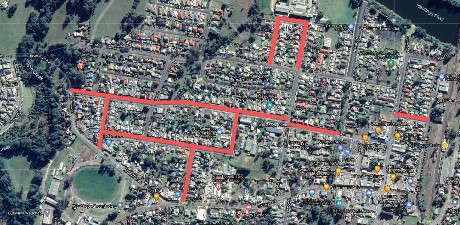
Figure 5. Basegrade Sites in Wauchope from 2017/18 Capital Works Program, NSW (Young, 2020)
Figure 6. Basegrade Stabilisation Candidate Sites in Raby Bay
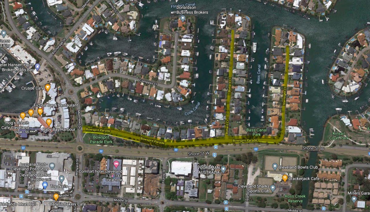
stabilisation solution was recommended to Council. The three roads were split into two separate design sections based on the condition of the subgrade, as illustrated below.
The base was a reasonably well graded Gravel (GP) while the subgrade was predominantly a Sandy Clay (CH) or Clay (CH). The gravel was only 165mm thick on average throughout the site. The subgrade material had soaked CBR’s ranging from 1.0% to 8% with swell characteristics as high as 11.0%, signifying a very highly expansive behaviour. The subgrade was also as high as 32% wetter than OMC which was indicative of the high water table given the reclaimed land and harbour side location.
Representative samples of the base gravel and subgrade were blended in the laboratory in proportions where the subgrade represented 15% and 40% for Sections 1 and 2 respectively. By following the Basegrade Stabilisation mix design
procedure, trial mix designs were performed using 60/40 slag/lime. Trial application rates varied for each site. UCS results are shown below.
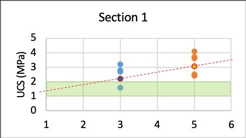
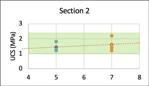
Figure 8. Trial Mix Design UCS Results
The mix designs adopted based on 1-2MPa target strengths were 2.0% 60/40 slag/lime and 5% 60/40 slag/lime for sections 1 and 2 respectively. Subsequently, the final designs implemented at Raby Bay for both sections are detailed below.
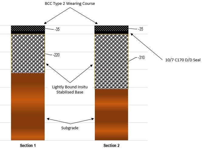
Figure 9. Basegrade Stabilisation Designs
Images of Bollard Court in Raby Bay illustrate below the condition of the site during and after basegrade stabilisation.
SUMMARY
Local Government’s use of pavement recycling in Australia through insitu stabilisation commenced in the 1950s after WWII. Basegrade stabilisation as a specific road rehabilitation technique comprising a blend of existing granular materials and subgrade materials has been applied on Australian local government roads since the 1970s, although it has never been categorically defined until 50 years later (Young, 2020). Further, published mix design procedures normally applied for basecourse or subgrade stabilisation are not suitable for basegrade stabilisation due to the distinct variances in material properties being assessed for treatment.
The mix design procedure for basegrade stabilisation developed in the 2020 research program provides a sound basis for use in local government.
One of the most encouraging trends from the research results which underpins the strong potential for success in using the mix design procedure, was the relatively small change in UCS with variations in the basegrade materials. This concept can be reflected in field conditions, usually under two situations. The first is when changes in material type occur within a project site (e.g. from a clay to a silt). The second situation to present variations in basegrade material properties is when the proportion of subgrade changes in the field. This is relatively common where the thickness of existing pavement gravels varies along the length of a site.
The Port Macquarie Hastings Council case study demonstrates the historical use of basegrade stabilisation, albeit with a trial and error approach to optimise the mix design. Subsequent to the release of the new basegrade stabilisation mix design procedure, Redland City Council were able to leverage off this technology and benefit from a solution that utilised the existing thin gravel and the poor quality subgrade clays to produce a lightly bound pavement base fit for a 20-year design period.
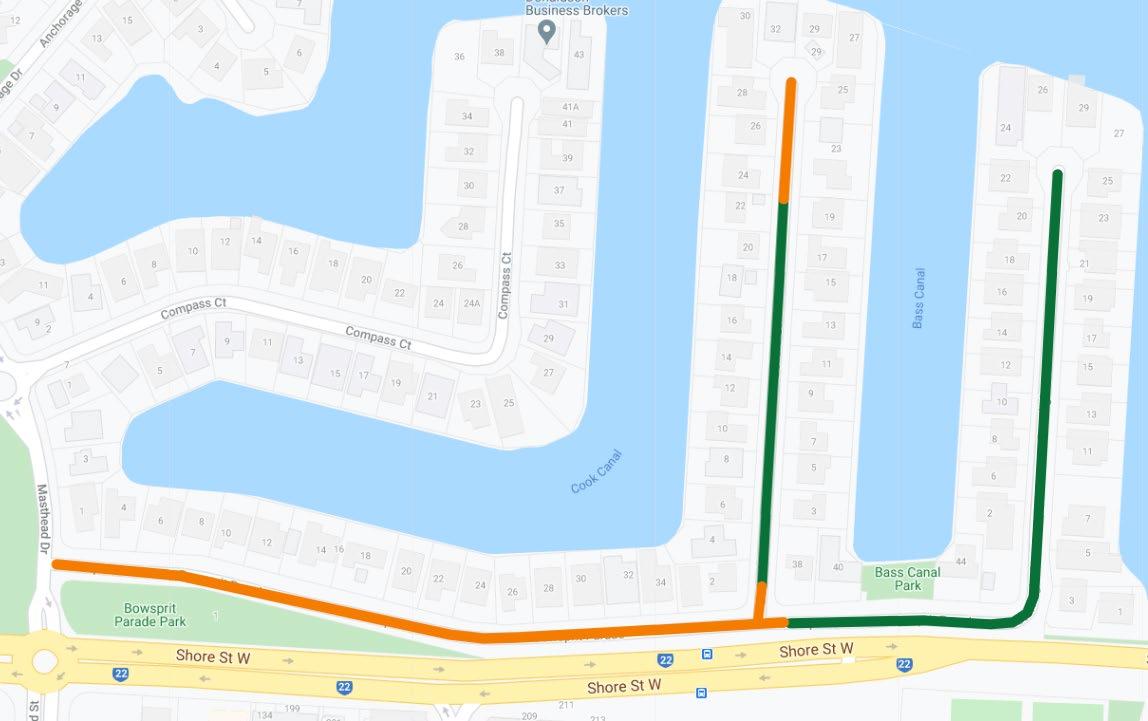
Figure 7. Basegrade Stabilisation Section 1 (green) & 2 (orange).
REFERENCES
Young, S. (2020). Development of a Mix Design Procedure for Basegrade Stabilisation.
Masters Thesis. Centre for Pavement Engineering Education.
[Online] http:// stabilisedpavements.com.au/ innovation
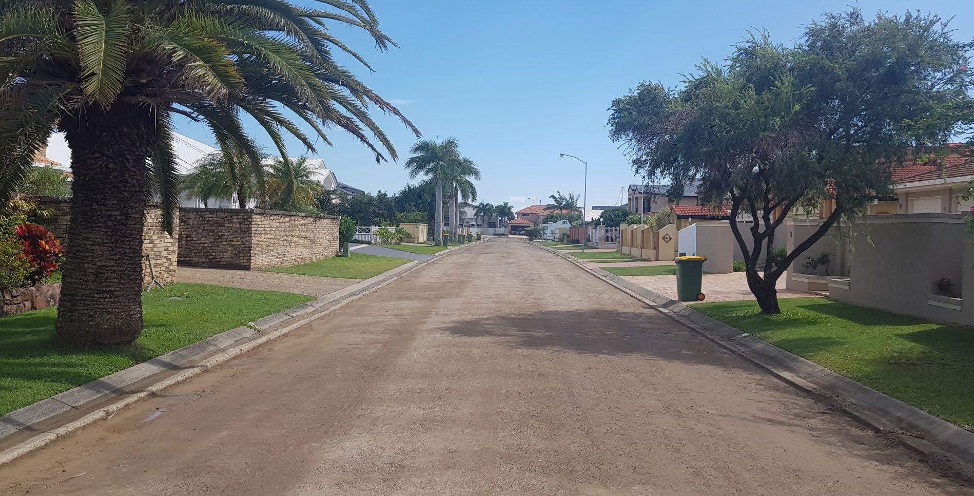
Figure 10. Bollard Court, Raby Bay (during construction).
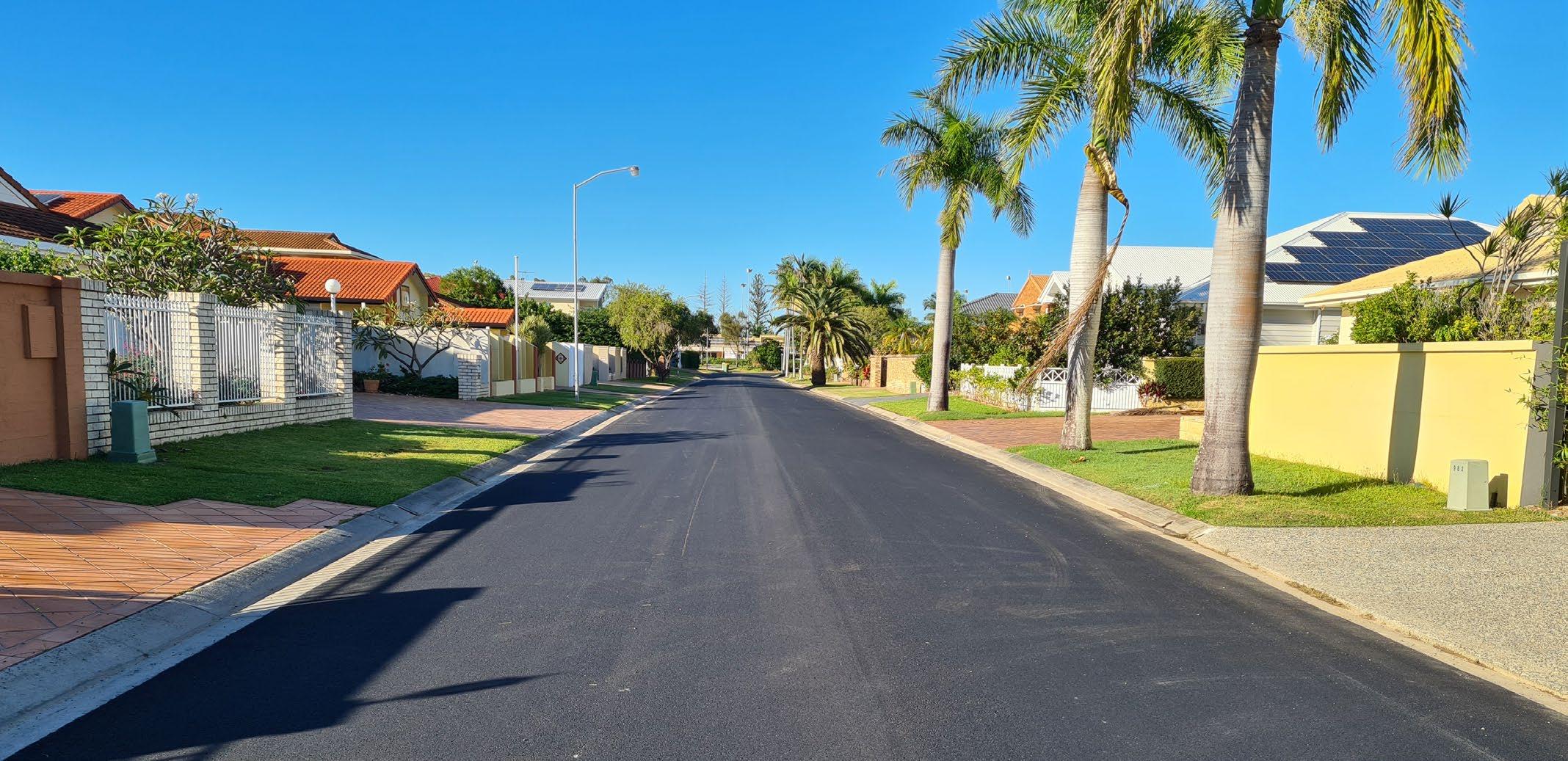
Figure 11. Bollard Court, Raby Bay (post construction).
ABOUT THE AUTHOR
Scott Young is the National Technical Manager for Stabilised Pavements of Australia (SPA) and also holds the position of Managing Director for the group’s Malaysian business, Stabilised Pavements Malaysia (SPM).
Scott is a Registered Professional Civil Engineer with Honours and holds a Masters’ degree in Pavement Technology.
Scott is a member of Professionals Australia, REAM, BPEQ and the Australian Chapter of the REAAA. He is a current technical committee member with the REAAA and is the Chairman of AustStab’s Technical Working Group. He has been heavily involved in the stabilisation industry for 20 years and during that time held positions of Director, Vice President and President in Australia’s national association AustStab.
His experience covers civil and geotechnical engineering, predominantly in pavements with areas of responsibility including asset management, structural design, performance specified maintenance contracts, asphalt production and laying, spray sealing, pavement rejuvenation and pavement recycling.


