
13 minute read
Isolation of a Critical Asset in the Water Supply Network
Craig Rieck Fraser Coast Regional Council
How do you take the largest water reservoir in your network offline for a period of three months for re-lining? The short answer is you bypass it. The reality (or the long answer) is that is takes 12 months of planning, trials and teamwork to ensure water security.
The Urraween Reservoir at 33 ML is the largest potable water storage in the Hervey Bay water supply network and is the main buffer storage for the majority of Hervey Bay suburbs. The reservoir is also the lowest in the network and has a pump station to boost the flow to the final gravity supply reservoirs before the reticulation network. The configuration of the reservoir site pipework has all flow entering the reservoir before being able to be pumped. Isolation of the reservoir would eliminate the existing pump station and limit flow to gravity, which was deemed to provide insufficient security of supply.
The reservoir is an earth-based dam style reservoir with a HDPE floor liner and geomembrane floating cover. The floating cover on the reservoir had reached the end of its useful life (22 yrs) and required replacement. To achieve this the reservoir had to be removed from service for a period of 3 months while the liner and cover material were removed and replaced.
The complexity was that, since it was 22 years since the last time this asset had been taken offline, there was no documented process to ensure water supply security.
This paper covers the process that Fraser Coast Regional Council went through to ensure the security of water supply during the period the reservoir was offline for refurbishment.
The Urraween reservoir is a critical asset in the potable water supply network for the Hervey Bay town site. The reservoir is the largest in the network and provides the following functions:
• Acts as buffer storage for peak consumption demands and as contingency in the event of a trunk main or treatment plant failure. The reservoir provides sufficient storage for approximately 2 days in summer and up to 5 days in winter • Provides a secondary supply to the two adjacent hospitals in the event of a failure in the reticulation network. Back supply is via a dedicated emergency pump station located on the reservoir site
• Maintains water quality via the dosing and monitoring of chlorine, as it is the only chlorine dosing station between the treatment plant and the customers
• Delivers boosted pumping of water to the reservoirs that supply customers via gravity, complicated by the fact that all water must flow through the reservoir to get to the pumps
• Bypass of the reservoir was via gravity only, with no pipework in place to allow pumping
The reservoir was constructed in 1990 from an ex-quarry site with part fill embankment and part excavation construction. At 138m long, 67m wide and 6.3m deep it holds a total of 33ML of potable water. It is a membrane lined earth reservoir made up of a floor liner from High Density
Figure One – Photo of Urraween Reservoir (prior to refurbishment).

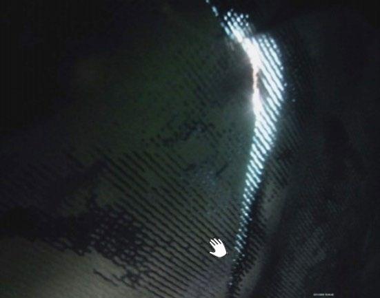
Figure Two – Photos of deteriorating condition of the floating cover.
Polyethylene (HDPE) and a floating membrane originally from polypropylene to form a storage bladder.
The floating cover was replaced in 1998 due to an early life failure while the floor liner was original from 1990. In order to ensure the quality of the water was maintained, having a sealed containment is of the utmost importance. After 22 years of service, the condition of the floating cover had started to deteriorate with several external patches already applied due to mechanical damage from rubbing of internal components used for rainwater drainage system. The regular internal dive inspection had highlighted that the cover was rapidly approaching the end of its useful life.
The declining condition of the floating cover had significantly increased the risk of water contamination and therefore required urgent replacement. Bladder material replacement would require the reservoir to be taken offline.
A tender package was developed and released for the replacement of the floor liner and floating cover with the contract awarded to a membrane specialist contractor whose proposed construction program would require the reservoir to be offline for a minimum period of 3 months. The contractor was to have no responsibility for isolation, draining, and filling with Wide Bay Water to be responsible for these functions.
The reservoir was last taken offline some 22 years ago with no documented procedures for ensuring water supply during periods of isolation, which was going to be a challenge. There were members of the Operations team that had been around since last isolation; but their recollection was that the reservoir was simply turned off due to a much smaller demand for water back then.
Isolation of the reservoir from a personal safety risk perspective was easy with valving already in-place to physically separate water from the reservoir internals but now that the reservoir was integral to the Hervey Bay supply network a detailed ‘security of supply plan’ was required.
The challenge was set; how to isolate the most critical reservoir in the network for a period of 3 months when it had not been done in recent history. The solution was in utilising the experience across all of our teams via a bit of old-fashioned teamwork to develop a plan that provided acceptable risk of supply.
The reality was 12 months of collaboration between the following stakeholders:
• Planning Department (internal) • Process Operations (internal) • Network Operations &
Maintenance (internal) • QLD Health (external) – adjacent hospitals that relied on the reservoir as an emergency supply
The process for developing a security of supply plan commenced with gaining a common understanding across all stakeholders of how the reservoir fitted into the supply network. Council currently uses a GIS mapping tool (Intramaps - infrastructure) to record the location and asset data for each of the individual components in the water network. However, using this as our primary tool communication/planning tool had the following issues:
• System doesn’t record the configuration (open or closed) status of the valving in the network
• Not a good visual tool for use in meetings as its resolution is poor at increased levels of zoom • Filtering of pipes based on size and not function (not easy to select trunk versus retic) • Designed to be used on screen and not as a paper tool during discussions in the field.
However, what Wide Bay Water did have across the teams were some very experienced individuals that had an immense knowledge of the network and its resilience to change. A
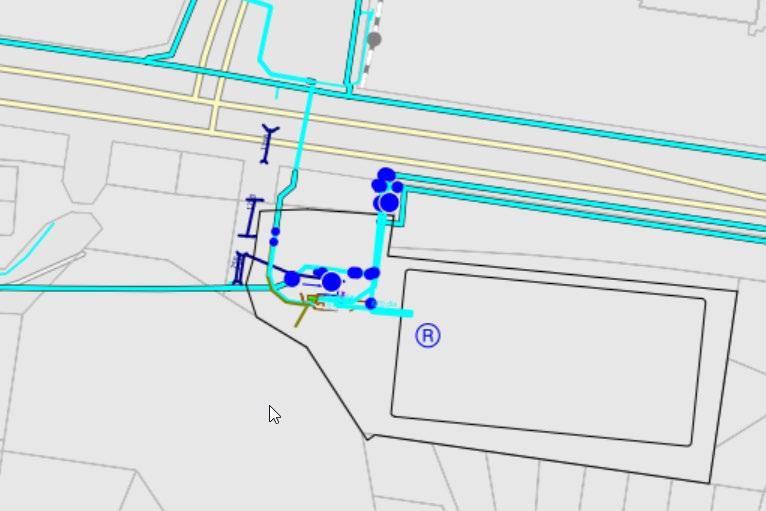
Figure Three – Screen Shot Showing the Reservoirs from GIS software.
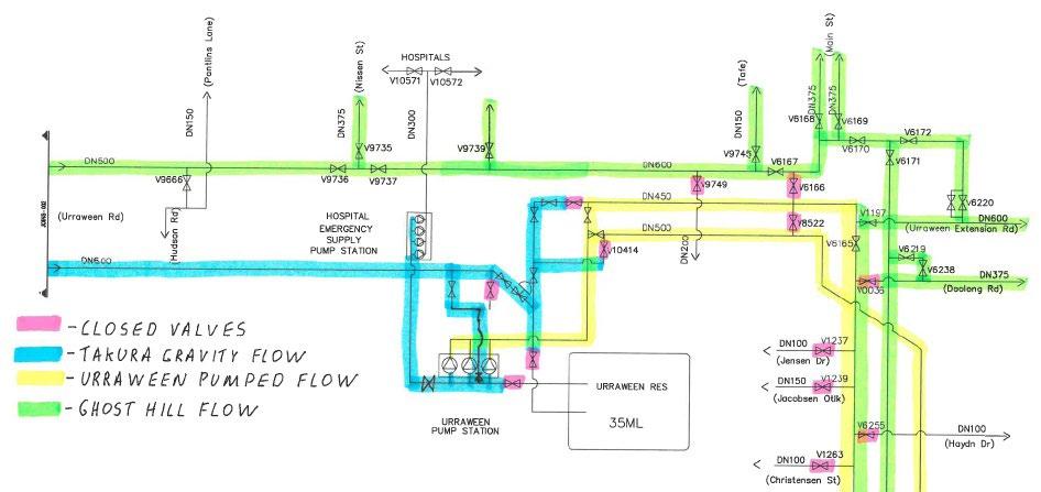
Figure Four – Network Schematic example.
simple visual tool was needed that could be stuck up on the wall during a meeting or taken out into the field for recording of configuration changes. This network schematic would then become the tool that was used to discuss alternatives, develop proposals for trials and record changes.
A network schematic (initially only from the treatment plant to the supply to customers) was developed as follows: • Hand sketched the network using the current GIS software • External drafting in AutoCAD to form a schematic
• Reviewed and amended by the operational teams • Configuration ‘for existing’ network recorded
Following the development of the network schematic, it was then time to understand consumption for the shutdown period to allow for assessment of the system resilience in dealing with changes to the network for the supply of water. The intent was to undertake the work during the winter period when consumption was at its lowest thereby reducing the load (and risk) on the network. Consumption data collected from the Supervisory Control & Data Acquisition System (SCADA) and water treatment plant production records was used to undertake modelling on alternative network configurations.
This initial data collection and modelling phase identified two main options for further review: • Gravity bypass • Easy to implement but contained risk around hourly peak consumption demands • Pumped bypass • Meet all demand requirements but would require further delays to project commencement
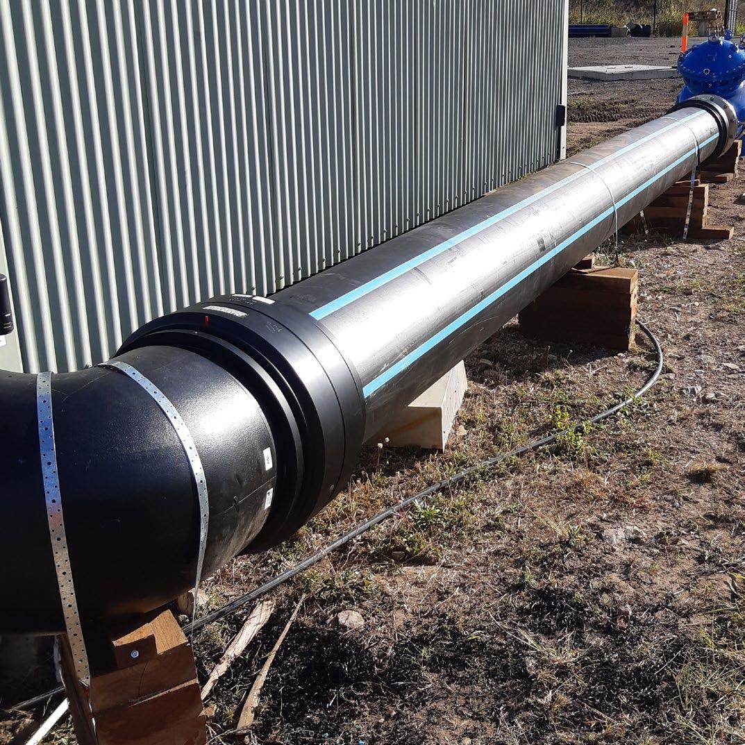
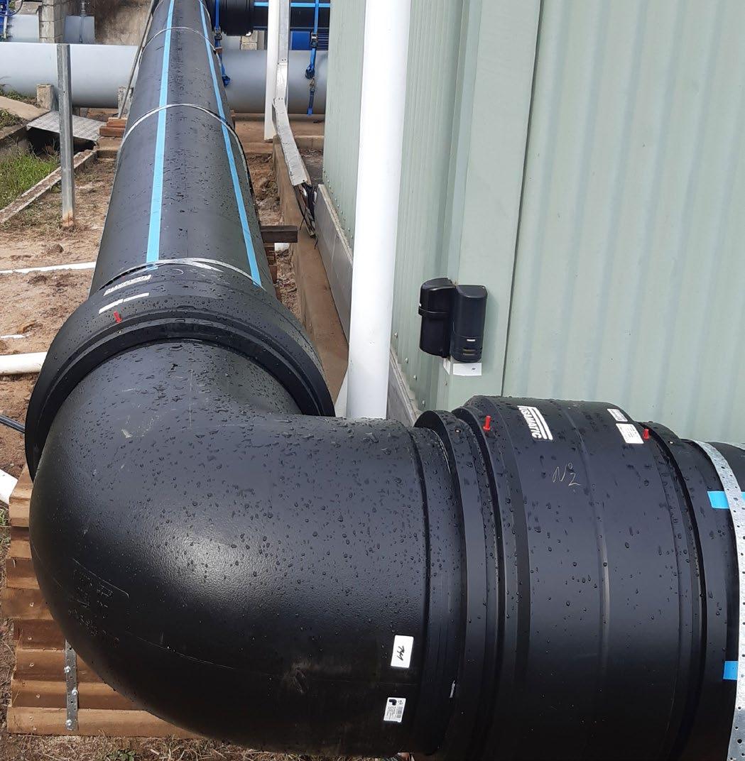
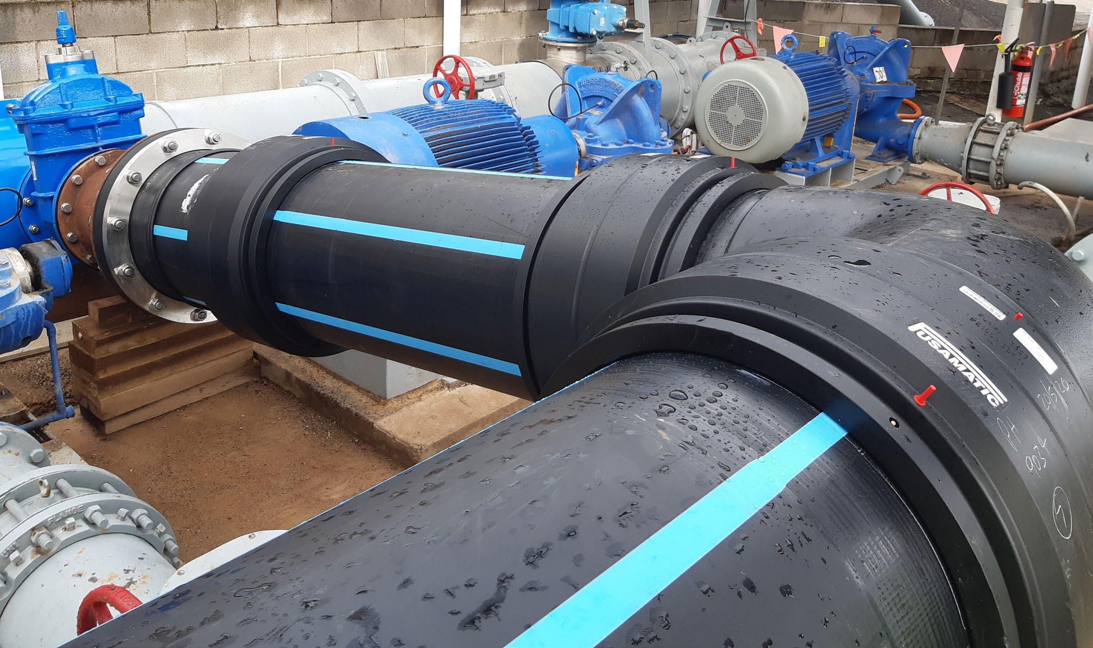
Figure Five – Photos of the installed bypass.
On detailed analysis of the gravity option, it was realised that the occurrence of peak flows during the morning and after peaks daily peaks could potentially cause supply interruptions and was abandoned in favour of a pumped bypass option.
Now that the pumped bypass option had been selected further options analysis was required to consider the use of the existing pump station at Urraween versus alternative portable pump bypass options. The major factors for consideration in determining the best solution were as follows:
• Provide peak flows in the order of 450L/s • Ability to deal with the high delivery pressures in the trunk main (>450kPa) • Availability of power and connection to the existing control system • Reliability and security of equipment to provide continuous supply
Analysis of possible options using the considerations above resulted in the selection of the existing pump station as the best solution and would require the design,
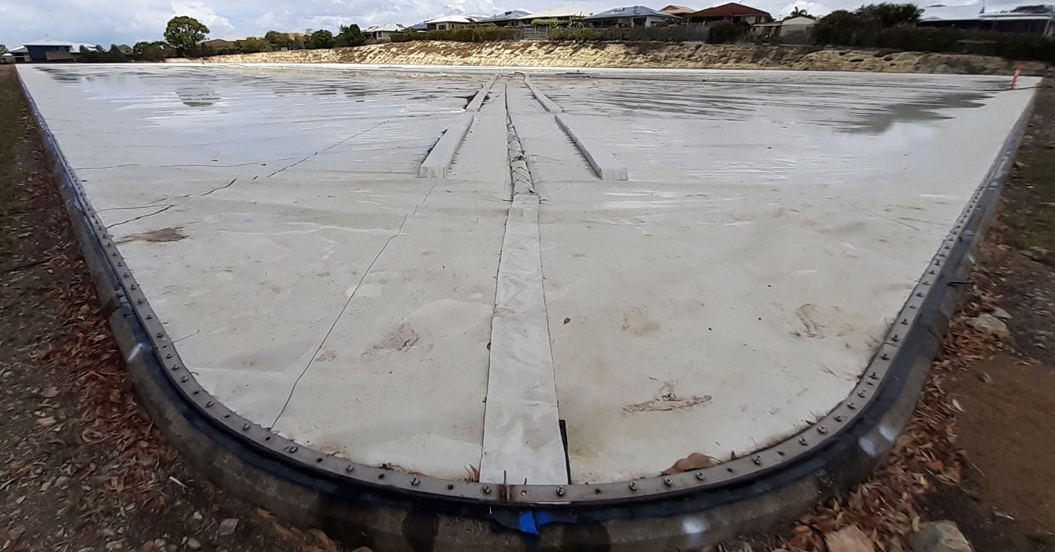
Figure Six – Reservoir Following Relining.
procurement and installation of temporary bypass pipework. This bypass pipework would take water direct from the incoming trunk main and route it to the suction side of the pumps to allow for the boosted supply.
Now that a pathway forward had been selected it was time to commence consultation with the primary stakeholders internally (networks and process operations) and externally with QLD Health to ensure all supply risks had been mitigated. Due to the reservoir providing an emergency back-up supply to the hospitals of Hervey Bay, lots of consultation was undertaken with QLD Health to develop alternatives in the event of a failure of the pumped bypass or the normal. Utilising the network schematic tool, we were able to develop a staged contingency plan that would ensure the hospitals would always be supplied with water.
In parallel to the stakeholder consultation process an inhouse design was undertaken for the bypass that resulted in the following major construction steps: • Pressure Reducing Valve (PRV) on the off take from the trunk
main (to deal with the high head pressures) • Installation of an additional valve in the pump station suction pipe work (to segregate the reservoir open to atmosphere surge pipe) • Installation of a tapping band on the suction manifold (to provide water supply to into the pumps) • Installation of HDPE above ground pipework (divert water prior to the reservoir into the pump station) • Installation of additional chlorine dosing pumps and pipework (to maintain water quality) • Modification to the control system software • Control of additional dosing • Provision for additional selfprotection
Since this bypass work would require temporary shutdowns of the reservoir, interim supply plans were needed to prove security of supply. As a starting point the previous consumption modelling work provided an understanding of the potential windows available to undertake the work but would require trialling. Undertaking a trial would provide the following: • Validation of the shutdown period available at low risk due to being able to revert to reservoir pumping at any time • Familiarisation to networks team of the valving configuration required • Data for the reverse calibration of the modelling software
Change control was managed by a set of documents specific to each step change in the network. The basis for each change management was as follows: • A plan document detailing the risk assessment • Network schematic detailing the specific valving configuration required • Change checklist to record the configuration changes
Following the installation work, bypass commissioning commenced including the hydrostatic testing of the pipework, adjustment of the PRV and Site Acceptance Testing (SAT) of the control system software. During this process further problems were identified with water hammer in the trunk mains that required further investigation.
Water hammer testing showed
that the pressure spikes were inherent to the original design of the pump station and were amplified by the bypass but were never identified previously as there was never any pressure monitoring undertaken during the pump station construction. As a result of this investigation operational risk assessments on the potential and consequence of failures were undertaken with the outcome being that this risk was to be accepted on the basis the risk of floating cover failure was deemed to be higher than trunk main failure.
The next phase was to test the reliability of the control system software by undertaking a 7-day Proof of Performance Test (PoPT) with final acceptance to be based on the following: • System to run in fully automatic without the need for operator intervention • Downstream reservoirs to remain at safe levels • Chlorine residuals to remain with limits and be stable
The PoPT was completed successfully and operational approval was given to bypass the reservoir based on the following: • Bypass system provided the same water supply boosting as per the existing • All stakeholders were kept informed throughout and were accepting of the risk • Gravity contingency plans had been developed and communicated
The reservoir could now be emptied, isolated and taken offline to allow the refurbishment works to be carried out. The reservoir was bypassed on 31 July 2020, 54.5 weeks after the process to determine isolation had begun.
Relining commenced shortly after with the reservoir being offline for a total of 3.75 months.
All of the efforts placed into planning and stakeholder engagement meant that the project was completed successfully with no supply interruptions and only one incident requiring shortterm implementation of a contingency supply plan (due to a mains failure on the inflow to the reservoir) were required throughout the duration of the project.
Acknowledgements
The author would like to thank the following people who contributed significantly to making this high risk project a success: Iain Everiss (Project Engineer) - for his commencement of the network schematic
Stephen Hinks (Water Treatment Superintendent) - for his guidance and support on risk management of the security of water supply
Robbie Muller (Network Coordinator) - for his knowledge and assistance during the development of the network schematic and contingency plans
Michael White (Principal Fitter) – for his support with all things mechanical
David Gibbs (Infrastructure Electrical Engineer) – for his guidance during control system development and implementation
ABOUT THE AUTHOR
Craig is a Mechanical Engineer who joined the Fraser Coast Regional Council in 2019 as an Infrastructure Delivery Engineer working in the Council’s Wide Bay Water Business Unit. Prior to joining Council, Craig worked as a Specialist Engineer with Rio Tinto in Western Australia delivering Rollingstock capacity expansion projects.
INFORMS. CONNECTS. REPRESENTS.MINI CONFERENCES LEADS.
Wastewater (109 minutes)
Topic
Townsville’s water supply and sewerage demand by land use
Mareeba Wastewater Treatment Plant Upgrade: Striking the balance between environmental and fi nancial sustainability
Yeppoon Sewage Treatment Plant Augmentation Project
Geopolymer Concrete - The Future of Wastewater Infrastructure? Speaker
Darron Irwin Dur.
26 mins
Glenda Kirk 30 mins
Jessica O’Hare and Eemonn Flynn 24 mins
Michael Kemp 29 mins


