
International Research Journal of Engineering and Technology (IRJET) e-ISSN: 2395-0056
Volume: 11 Issue: 11 | Nov 2024 www.irjet.net p-ISSN: 2395-0072

International Research Journal of Engineering and Technology (IRJET) e-ISSN: 2395-0056
Volume: 11 Issue: 11 | Nov 2024 www.irjet.net p-ISSN: 2395-0072
Pratish R. Siddheshware , Prof. Shaikh A.N.
Student, Department of Civil Engineering, M.S.Bidve Engineering College, Latur, Maharashtra, India
Professor, Department of Civil Engineering, M.S.Bidve Engineering College, Latur, Maharashtra, India
Abstract - Unavailability of plain ground in mountainous regions necessitated construction of framed building on sloping ground. In present study, the structure is totally commercial building. The structure is examined for seismic zone III and soil condition is hard consider. The structure is compared the sloping ground and plain ground and also with and with-out bracing system. The different model is done on STAAD.pro software. Some model is analysis on plain ground and sloping ground with-out Bracing system and some model is analysis on plain ground and sloping ground with- Bracing System. The different slope is 10degree, 20-degree and 30- degree is considered while analysis. The bracing is considered at outer peripherals and at Centre of core. The Models are analysis for various aspects like Story Displacement, Storey overturning moment, Storey Drift, Lateral Displacement, etc. In this research P-delta is not Consider. This help us understand detailed analysis of behaviour of building under different slopingangles andeffect ofearthquake onbuilding.
Key Words: STAAD.Pro,SlopingBuilding,Stepback, Bracingsystem,HighriseBuilding
1.INTRODUCTION
Generally,allbuildingsareconstructedonhorizontalplain levelground.Inthehillyregionhavingslopinggrounditis hardtobuildthemultistoreystructures.Theconstructions of the building now days are progress on sloping ground due to lack of horizontal plain level ground. These hill regions are the most hazardous view shows sometimes duetosomenaturalcalamitieslikelandsidesandseismic activity.
Earthquakes arise alongside plate margins (where inflate meets) while plate move fast, in the direction or farf rom other,theactionsisnotalwayssosmooth.Frictioncauses the plates to get struck. This causes the pressure to build upofpressurereleased.Earthquakesareusuallyclassified on the basis of causes of origin, depth of focus, Intensity andmagnitude ofearthquake.Earthquakeismeasured by using Ritcher magnitude scale anything is greater than magnitude7consideredassevertypeofEarthquake.
Due to increase in population and rapid urbanization, the scarcity of plain ground is happened. Since structures are constructed in hilly area. The construction of building in
hillyareaisnoteasycomparedtobuildinginplainground. Insomehillyregionsoftheworldaremoreprontoseismic activity, In India, North and northeast part have large slopinggroundsandconstructionofRCbuildingispopular inslopingground.Earthquakecausesshakingofgroundso building resting on slope will experience motion at its base. Even though the base of the building moves with ground.Roofhastendencytostayinoriginalposition.But since the walls and columns are connected toit, they drag the roof along with them. Earth quakes are the natural phenomenon which are caused by the release of large strainenergybythemovingfaultsbelowthesurfaceofthe earth,whichultimatelycausestheshakingoftheearthtop surfaceinallpossibledirectionswithdifferentamplitudes andintensitiesoflateralforces.
Ashraf. (1998)
Ashrafetal.(1998)presentsthestepsusedinperforming a pushover analysis of a simple three-dimensional building. SAP2000, a state-of the-art, general purpose, three-dimensional structural analysis program, is used as a tool for performing the pushover. It allows quick and easy implementation of the pushover procedures described in the ATC-40 and FEMA-273 documents for both two and three-dimensional buildings. He suggested that it is easy to investigate the erect of different strengthening schemes and also to stiffen or strengthen the building by changing the member properties and rerunningtheanalysis.
Armagan Korkamaz et al. evaluated the performance of frame structures for various load patterns and variety of natural periods by performing pushover and non-linear dynamic time history analysis. Pushover and non-linear time history analyses results are compared to choose the best load distribution for specific natural period for this type of frame structure. They concluded that the shear failure of the columns is experienced at the larger storey displacements and rectangular distribution always give the higher base shear-weight ratio comparing to other load distributions for the corresponding story displacement. The rectangular load distribution shows maximum seismic demands during the given earthquakes morereasonablethantheotherloaddistribution
International Research Journal of Engineering and Technology (IRJET) e-ISSN: 2395-0056
Volume: 11 Issue: 11 | Nov 2024 www.irjet.net p-ISSN: 2395-0072
A.Meher Prasad et al. (2004) studied the effect of infill stiffnessonseismicperformanceofmulti-storeyRCframed buildingsinIndia.Twotypicalexistingbuildingslocatedin moderateseismiczonesofIndia(asperIS:1893-2002[1]) are identified. Features like plan irregularity and vertical irregularity(softstorey)arefoundinoneofthebuildings, while the other is fairly symmetric. Infill’s were modelled using the equivalent strut approach. Static analysis (for gravityandlateralloads),responsespectrumanalysisand non-linear pushover analysis werePerformed. It is observed that the seismic demand at the soft storey level is significantly large when infill stiffness is considered, withlargerbaseshearandlargerdisplacements.
A.Fiore et al. (2012) studied about the inuence of infilll panels over the collapse mechanisms activated under pushover analysis. a large number of research studies have been recently devoted to the modelling and analysis of inflled RC framed buildings under seismic actions, and the significant role that the infill plays in the overall structural performance is by now a well acknowledged result.Inparticular,theextensionofN2methodtoinfilled frame allows the appraisal of this contribution within the framework of a nonlinear static analysis. Numerical analyseswereperformedbyusingspatialmodels,bothfor the bare frames and in filledframes, in order to appraise the variation of the structural capacity because of the interactionoftheinfillswiththeRCelements.
Anoop Singh , Vikas Srivastava , N.N.Harry
Anoop Singh , Vikas Srivastava , N.N.Harry has concluded that The displacement of beam coming in the building is withinthelimitsofIndian standards. This buildingis safe for area coming under earthquake zone II. The maximum drift in the building is 2.077 cm which is safe as per IS 1893-2002. The maxim drift in the building is 2.077 cm which is safe as per IS 1893-2002. The maximum beam displacementof3mspanbeamis0.044mmandallowable displacementis12mm.
Sachin Kumar Dangi ,
SachinKumarDangi,andSaleemAkhtarhadsaidthereis significantimprovementobservedinseismicperformance of building on sloping ground by providing shear walls with different configurations since lateral displacement andmemberforcesreduceconsiderablyinbuildingdueto provision of shear walls. It is observed that maximum displacement is found in case of45 slope without shear wall. Hence we can say that, risk increases with the inclination of the slope. In this study we found that, the position of the shear wall at periphery is the optimumposition for the lateral load resistance. It is observed that, the position of the shear wall at corner is the optimum position for countering axial loads. It is observed that, maximum shear force and maximum
bending momentincreasesignificantly for slopingground at45slope.Itisobservedthat,axialforceincreasesinthe buildingswithshearwall.Baseshearisfoundmaximumin thebuildingwithshearwall,duetodeadloadoftheshear wall.
B.G. Birajdar , S.S. Nalawade has said The performance of STEP back building during seismic excitation could prove more vulnerable than other configurations of buildings. The development of torsional moments in Step back buildings is higher than that in the Step back Setback buildings.Hence,StepbackSetbackbuildingsarefoundto belessvulnerablethanStepbackbuildingagainstseismic ground motion. In Step back buildings and Step back-Set backbuildings, it is observed that extreme left column at ground level, which are short, are the worstaccepted. Special attention should be given to these columns in design and detailing. Although, theSet back buildings on plaingroundattractlessactionforcesascomparedtoStep back Setback buildings, overall economic cost involved in levelingtheslopinggroundandotherrelatedissuesneeds tobestudiedindetail.
Various research paper compared the buildings with different seismic zones, with different climatic conditions, different land profiles but there is very less research regarding effect of slopes on the building with varying seismiczones.InthisprojectwehavecomparedaBuilding fordifferentslopeslike0,10,20,30degreeslopeandvary seismiczoneslikesI,V.
Theobjectiveofthisproject isa Comparativestudyofthe effect of slopes on a building in with and without bracing system.Inthisproject,wearegoingtoanalyzemultistory building in varying slopes by using software like STAAD. Pro. In this project, we are going to structurally compare the G+10 , G+20,G+30 story building with various slopes like 0, 10, 20, 30 degree and with different seismic conditions like Zone I and Zone V. And at the end we will findsomeresults.Theresultsinclude
1. PlanDimension24mx22.5m
2. StoryHeight3.5m
3. Numberofstories
i) InG+10=11stories
ii) InG+20=21stories
iii) InG+30=31stories
ThefollowingWindLoadparametersweretakenasperIS 875(Part3):
WindSpeed,Vb(m/s) 47
International Research Journal of Engineering and Technology (IRJET) e-ISSN: 2395-0056
Volume: 11 Issue: 11 | Nov 2024 www.irjet.net p-ISSN: 2395-0072
Terraincategory 3
Structureclass C
RiskCoefficient(k1factor)1
Topography(k3factor)1
4.1 Lateral Load Parameters
ThefollowingEarthquakeLoadParametersweretakenas perIS1893:2002:
Responsereductionfactor(R) 5
Seismic zone- III
Seismiczonefactor(Z)0.16
Soiltype-II
Importancefactor -1
TimeperiodProgramcalculated
4.2 Load Definitions
Thefollowingloadhasbeenconsideredtobeactingon boththestructures:
Deadload:weightofthestructure.
Superimposedloadduetofinishingetc.:1kN/m2
LiveLoad:3kN/m2
EarthquakeinX-directionAsperIS1893:2002
EarthquakeinY-direction:AsperIS1893:2002
Windload:AsperIS875(Part3)
4.3 Frame sections
Column–Isection–I100012B55020
Beam-Isection–I80012B50012
ChannelSection -ISA125 SlabThickness -120mm
5. STAAD Pro Models
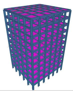
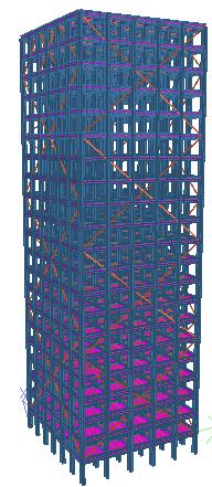
6. RESULTS AND DISCUSSION
Response Spectrum analysis for seismic loading while linearstaticanalysisforwindloadinghasbeencarriedout for all the structures using STAAD.Pro and the results are representedinthefollowingform:
Maximumtopstoreydisplacement
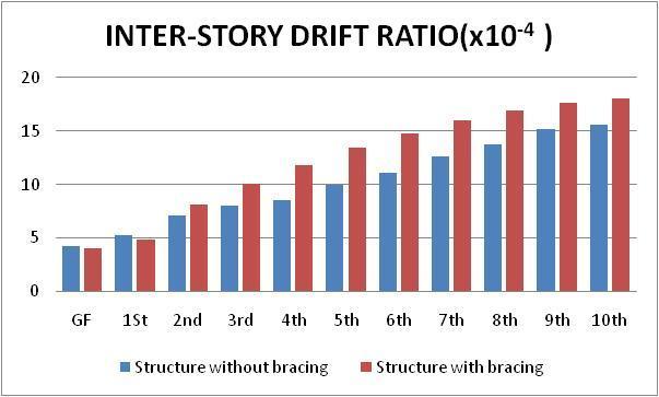
Interstoreydrift
Comparativestudybetweenabuildingonslopinggrounds with some slope having with and with bracing system. In this report structure is considered with and without any slope G+10,G+20,G+30 and analyses is done. Tabulated resultandgraphsareas below
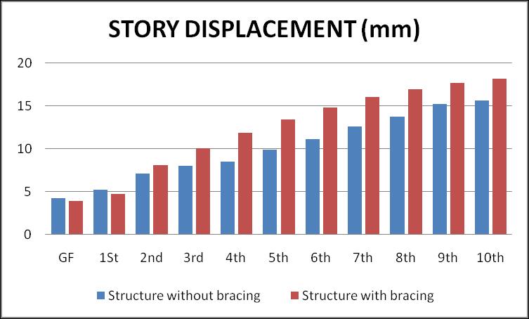
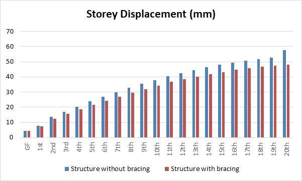
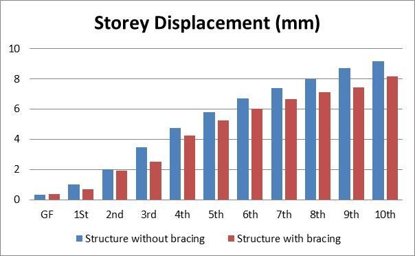
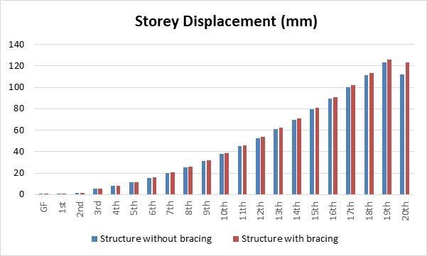
STORY DISPLACEMENT (mm)
Table-1–G+10buildingwithoutanyslope
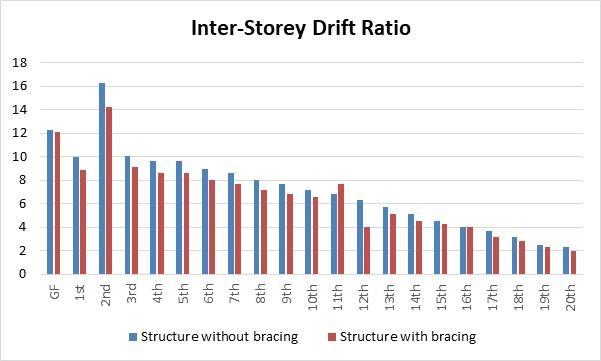
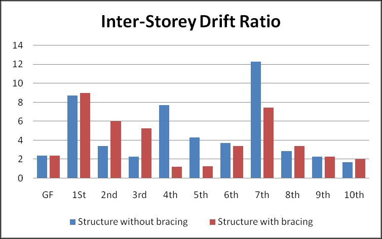
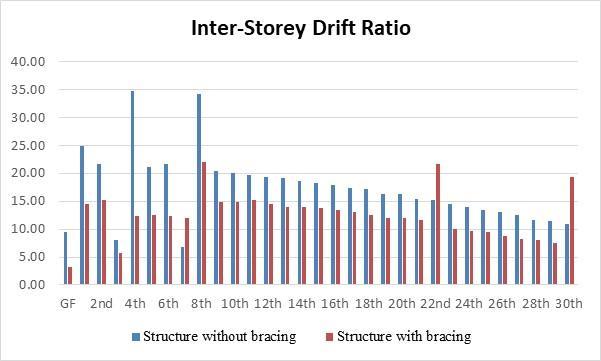
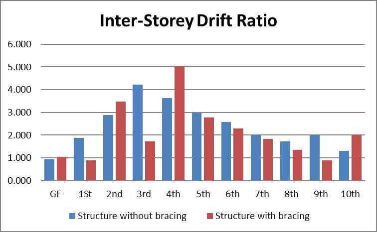
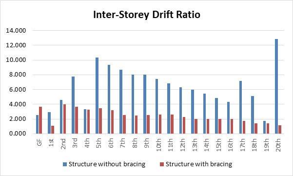
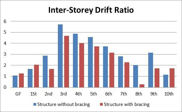
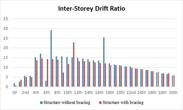
INTER-STORY DRIFT RATIO (x10-4)
Table-2–G+10buildingwithoutanyslope
International Research Journal of Engineering and Technology (IRJET) e-ISSN: 2395-0056
Volume: 11 Issue: 11 | Nov 2024 www.irjet.net p-ISSN: 2395-0072
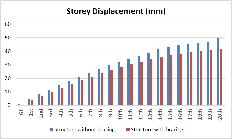
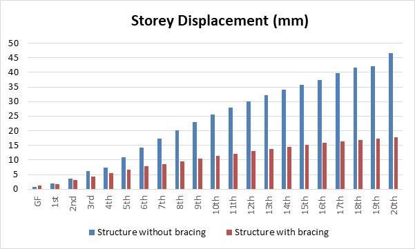
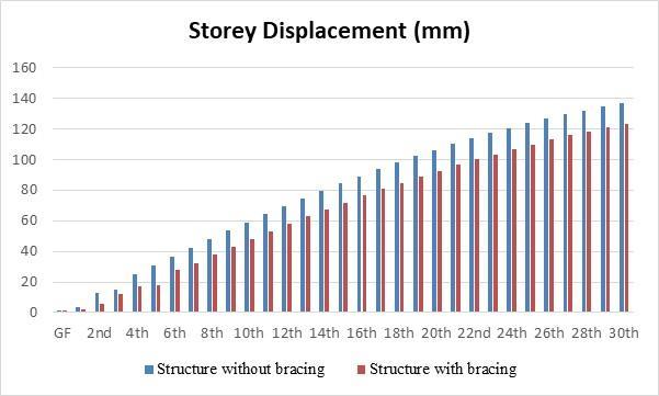
STORY DISPLACEMENT (mm)
Table-3–G+20buildingwithoutanyslope
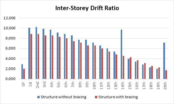
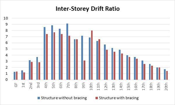
INTER-STORY DRIFT RATIO (x10-4)
Table-4–G+20buildingwithoutanyslope
International Research Journal of Engineering and Technology (IRJET) e-ISSN: 2395-0056
Volume: 11 Issue: 11 | Nov 2024 www.irjet.net p-ISSN: 2395-0072
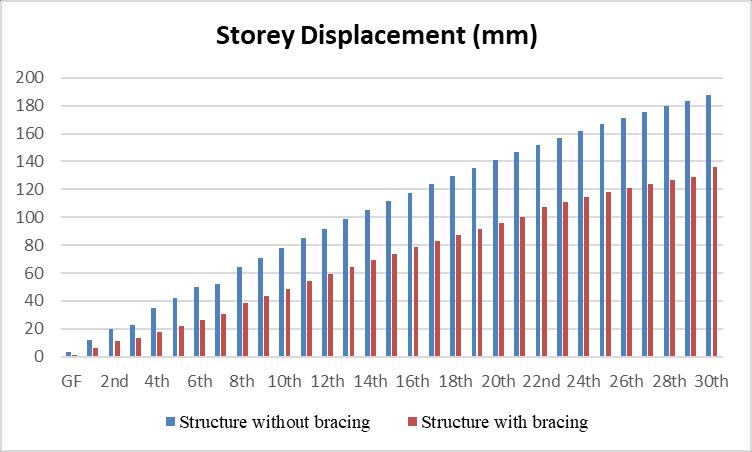
Table-5–G+30buildingwithoutanyslope
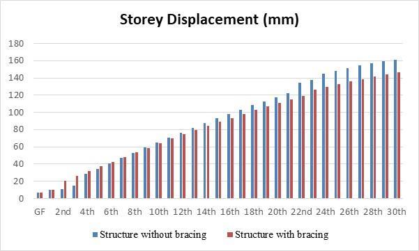
Table-6–G+30buildingwithoutanyslope
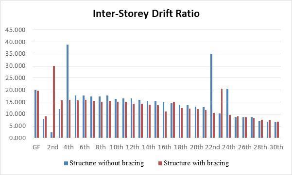
Table-7–G+10buildingwith10degreeslope
International Research Journal of Engineering and Technology (IRJET) e-ISSN: 2395-0056
Volume: 11 Issue: 11 | Nov 2024 www.irjet.net p-ISSN: 2395-0072

INTER-STORY DRIFT RATIO (x10-4)
Table-8–G+10buildingwith10degreeslope
STORY DISPLACEMENT (mm)
Table-9–G+20buildingwith10degreeslope
INTER-STORY DRIFT RATIO (x10-4)
Table-10–G+20buildingwith10degreeslope
International Research Journal of Engineering and Technology (IRJET) e-ISSN: 2395-0056
Volume: 11 Issue: 11 | Nov 2024 www.irjet.net p-ISSN: 2395-0072
STORY DISPLACEMENT (mm)
Table-11–G+30buildingwith10degreeslope
INTER-STORY DRIFT RATIO (x10-4)
Table-12–G+30buildingwith10degreeslope
International Research Journal of Engineering and Technology (IRJET) e-ISSN: 2395-0056
Volume: 11 Issue: 11 | Nov 2024 www.irjet.net p-ISSN: 2395-0072
STORY DISPLACEMENT (mm)
Table-14–G+10buildingwith20degreeslope
STORY DISPLACEMENT (mm)
Table-13–G+10buildingwith20degreeslope
INTER-STORY DRIFT RATIO (x10-4)
Table-15–G+20buildingwith20degreeslope
International Research Journal of Engineering and Technology (IRJET) e-ISSN: 2395-0056
Volume: 11 Issue: 11 | Nov 2024 www.irjet.net p-ISSN: 2395-0072
INTER-STORY DRIFT RATIO (x10-4)
Table-16–G+20buildingwith20degreeslope
STORY DISPLACEMENT (mm)
Table-17–G+30buildingwith20degreeslope
International Research Journal of Engineering and Technology (IRJET) e-ISSN: 2395-0056
Volume: 11 Issue: 11 | Nov 2024 www.irjet.net p-ISSN: 2395-0072
DRIFT RATIO (x10-4)
Table-19–G+10buildingwith30degreeslope
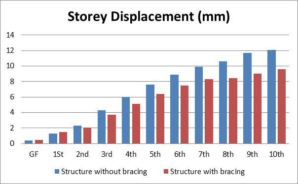
Table-18–G+30buildingwith20degreeslope
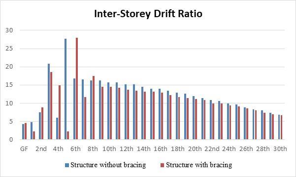
Table-20–G+10buildingwith30degreeslope
International Research Journal of Engineering and Technology (IRJET) e-ISSN: 2395-0056
Volume: 11 Issue: 11 | Nov 2024 www.irjet.net p-ISSN: 2395-0072
STORY DISPLACEMENT (mm) Story
Table-21–G+20buildingwith30degreeslope
INTER-STORY DRIFT RATIO (x10-4)
Table-22–G+20buildingwith30degreeslope
International Research Journal of Engineering and Technology (IRJET) e-ISSN: 2395-0056
Volume: 11 Issue: 11 | Nov 2024 www.irjet.net p-ISSN: 2395-0072
Table-23–G+30buildingwith30degreeslope
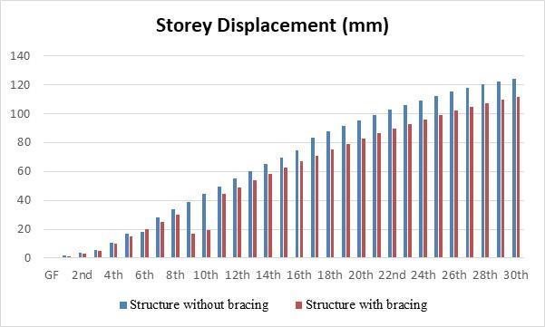
Table-24–G+30buildingwith30degreeslope
Following conclusion observed after analysizing different G+10, G+20, G+30, structure with different sloping angle as0,10,20and30degree.Resultsarecomparedforstory displacement,maximumbaseshareandstoryshare,which show behaviours of structure with and without bracing, andwhicharebelow,
1.Forstorydisplacement
a. Considering G+10 building results are compared which shows that, Building with out bracing without for same loading and same section property. It has been observed that story displacement is increased with height of the buildingandwhichisvaryingfrom9mm to16mm.Same observation made building with bracing that story displacementisdecreased withheight ofthe building and which is in the range of 8.15 mm to 15.3 mm except for zero degree slope. Overall improvement in story displacement which is around 5 to 6 % less for building
International Research Journal of Engineering and Technology (IRJET) e-ISSN: 2395-0056
Volume: 11 Issue: 11 | Nov 2024 www.irjet.net p-ISSN: 2395-0072
withbracing.Henceresultsshowthatstorydisplacements in the structure reduced when structure is provided with bracing.
b. Considering G+20 building results are compared which shows that, Building without bracing without for same loading and same section property. It has been observed that story displacement is increased with height of the building and which is varying from 9.1 mm to 112 mm. Same observation made building with bracing that story displacementisdecreased withheightofthebuildingand which is in the range of 4.1 to 41.8 mm except for thirty degree slope. Overall improvement in story displacement whichisaround20%lessforbuildingwithbracing.Hence results show that story displacements in the structure reducedwhenstructureisprovidedwithbracing.
c. Considering G+30 building results are compared which shows that, Building without bracing without for same loading and same section property. It has been observed that story displacement is increased with height of the building and which is varying from 124mm to 187 mm. Story displacement is decreased with height of the buildingforstructurebracingandwhichisintherangeof 111 to 146 mm. Overall improvement in story displacement which is around 20 %less for building with bracing. Hence results show that story displacements in the structure reduced when structure is provided with bracing.
D. Kornack and P. Rakic, “Cell Proliferation without Neurogenesis in Adult Primate Neocortex,” Science, vol. 294, Dec. 2001, pp. 2127-2130, doi:10.1126/science.1065467.
M. Young, The Technical Writer’s Handbook. Mill Valley, CA:UniversityScience,1989.
R.Nicole,“Title ofpaper withonlyfirst wordcapitalized,” J.NameStand.Abbrev.,inpress.
K.Elissa,“Titleofpaperifknown,”unpublished.