
International Research Journal of Engineering and Technology (IRJET) e-ISSN:2395-0056
Volume: 11 Issue: 11 | Nov 2024 www.irjet.net p-ISSN:2395-0072


International Research Journal of Engineering and Technology (IRJET) e-ISSN:2395-0056
Volume: 11 Issue: 11 | Nov 2024 www.irjet.net p-ISSN:2395-0072
S.Y.Sayais1 , Sakshi Rajput2 , Sanika Patil3 , Vaishnavi Nikumbh⁴, Gaurav Shisode⁵ , Mahesh Nikam⁶
1Assistant Professor, Department of Electrical Engineering, R.C. Patel College of Engineering, Shirpur, India 2,3,4,5,6Student, Department of Electrical Engineering, R.C. Patel College of Engineering, Shirpur, India
Abstract -This project presents the design and implementation of overvoltage and undervoltage load protection system using Arduino Uno. The main purpose of these system is to provide the protection from overvoltage and undervoltage in system. Voltage fluctuations can severely impact electrical equipment, making it critical to develop a system that can detect and respond to unsafe voltage levels in power system. This project is designed to safeguard electrical equipment from harmful voltage fluctuations, the system continuously monitors voltage levels, disconnecting the load when values exceed safe limits. The Arduino processes real-time voltage data and displays it onthe LCD,activating arelayto cut offpower if needed. By leveraging the capabilities of the Arduino Uno, the system achieves high reliability and flexibility while remaining cost-effective. This low-cost system demonstrates reliable protection for residential and industrial applications, enhancing safety for sensitive devices. The research aims to contribute a viable solution for enhanced load protection in both industrial and residentialsetting
Key Words: Overvoltage, Undervoltage, Load Protection, Arduino Uno, LCD Display, Voltage Monitoring
Voltage stability is essential for the safe operation of electrical devices, yet fluctuations such as overvoltage and undervoltage are common due to grid issues, load variations, and environmental factors. Such voltage fluctuations can lead to irreversible damage, reduced performance, and even operational hazards in sensitive equipment. Overvoltage and undervoltage conditions can result in excessive strain on electrical appliances, lead to irreversible damage, inefficiencies, and even operational hazards in sensitive equipment, safety risks like overheating or fires. While industrial-grade voltage protection systems exist, they are often complex and expensive, making them impractical for average householduse.Tominimizethisissueswemadeasimple, cost-effective overvoltage and undervoltage protection
system suitable for domestic use. By leveraging the capabilities of an Arduino Uno microcontroller and LCD display, this project aims to create a system that not only protects household appliances but also provides an easyto-use interface for monitoring real-time voltage. The primaryobjectiveistodetectdangerousvoltagelevelsand automatically disconnect the load to prevent potential damageorhazards.
Several studies have explored microcontroller-based solutions for voltage regulation and protection. Research has demonstrated the efficacy of Arduino platforms in monitoring and controlling electrical systems due to their programmability, affordability, and ease of integration withvarioussensorsanddisplaydevices.
• Microcontroller-based voltage monitoring systems: Research has shown that microcontrollers are effective in monitoring electrical parameters and implementing real-time protection measures. As we know Arduino is easy, reliable and open source microcontroller Arduino-based systems, in particular, offer a reliable solution for detecting voltage variations and protecting connected devices due to their rapid processing capabilities and real-time response. Prior studies have shown that Arduino-based voltage monitoring systems provide reliable, real-time data on voltage levels and have been successfully used in both industrialandresidentialsettings.
• Arduino as a platform for electrical monitoring: The Arduino platform has been shown to be highly effective for electrical monitoring due to its ease of programming, affordability, and compatibility with a rangeofsensorsandmodules.Researchsupportsitsuse in voltage regulation projects as it allows for real-time, precisevoltagemeasurementandcontrolandreliable.
• Affordability and accessibility of arduino: Dueto its low cost and wide availability and open source microcontroller, the Arduino is an ideal choice for most

International Research Journal of Engineering and Technology (IRJET) e-ISSN:2395-0056
Volume: 11 Issue: 11 | Nov 2024 www.irjet.net p-ISSN:2395-0072
residential and small-scale applications. Researchers have noted its affordability compared to other platforms, making it a practical option for household voltageprotectionsystems.
• Application in industrial and residential settings: Arduino-based systems have been successfully used in both industrial and domestic contexts. Research findings highlight their adaptability, noting that the same platform can be customized for different voltage ranges and operational requirements, ensuringflexibilityacrossdifferentapplications.
• Relay-controlled load protection: Relay mechanisms are commonly used in voltage protection circuits to control the connection and disconnection of loads. This project leverages a similar setup, enabling theArduinotoactivateordeactivatetherelaybasedon voltagereadings.
• User interface with LCD (liquid crystal display) displays: LCD displays are used in various applications for real-time feedback. In this project, the LCDshowsvoltagelevelsandalertsuserswhenvoltage conditions exceed safe limits, enhancing the system’s usabilityforhouseholdsettings.
• Enhanced safety in household applications: We havenotedthatArduino-basedsystemswithrelaysand LCDs significantly improve household safety. By disconnecting the load automatically in response to dangerous voltage levels, these systems protect both equipment and occupants, underscoring their practical applicationindomesticenvironments.
3. COMPARE EXISTING SYSTEM AND PROPOSED SYSTEM
TABLE-1:ComparisonbetweenExistingSystemand ProposedSystem
Feature MCB Overvoltage/Undervoltage ProtectionSystem(Arduino)
ProtectionType Overcurrent (overload and short circuit) Overvoltage and undervoltage
ResponseTime Milliseconds Milliseconds, with minimal processingdelay
Manual/Auto Reset Manualreset Automatic reset or configurable
Monitoring None LCD display with real-time voltageinformation
UsageScope General household and industrialuse
Customization Limited High, based on code and settings
Cost Low Moderate (due to components like Arduino, relay,LCD)
Function: MCBs are electromechanical devices that protect electrical circuits from overcurrent due to overloads or short circuits. They trip and cut off the powersupplywhenthecurrentexceedsapre-setlimit.
• Protection Level: MCBs provide basic protection againstoverloadsandshortcircuitsbutcannotprotect against voltage fluctuations such as overvoltage or undervoltageconditions.
• Response Time: Very fast response to current-related faults,typicallyinmilliseconds.
• Reset Mechanism: MCBs can be manually reset after tripping.
• Usage: They are widely used for home and industrial circuitprotectionduetotheirsimplicityandreliability.
Limitation:
• Doesnotdetectorprotectagainstvoltagefluctuations.
• Limited protection functions focused only on current, notvoltage.
• Nodiagnosticormonitoringfeatures.
3.2 Overvoltage/Undervoltage Load Protection System using Arduino Uno
Function: This system is designed to monitor voltage levels and provide protection by disconnecting the load when voltage exceeds safe levels, either in cases of overvoltageorundervoltage.
Components:
1. Arduino Uno: Serves as the controller to monitor and processvoltagelevels.
2. VoltageSensors:Detectsovervoltageandundervoltage conditions.
3. Relay Module: Acts as a switch to disconnect or reconnecttheloadbasedonvoltagelevels.
Sensitive devices and areas with voltage fluctuation issues
4. LCD Display: Displays real-time voltage readings, alerts,orstatusofthesystem.
5. ProtectionLevel:Canprotectagainstbothovervoltage and undervoltage, providing a more comprehensive protectionsystemforsensitivedevices.

International Research Journal of Engineering and Technology (IRJET) e-ISSN:2395-0056
Volume: 11 Issue: 11 | Nov 2024 www.irjet.net p-ISSN:2395-0072
6. Response Time: Quick but can be slightly delayed by sensorandprocessingtime,usuallyinmilliseconds.
7. -Reset Mechanism: Can be programmed to automatically reset when normal voltage levels are restored.
8. Usage: Suitable for areas with frequent voltage fluctuations,providingatailoredsolutionforsensitive electronicequipment.
Advantages:
• Can detect and react to both overvoltage and undervoltagesituations.
• Provides real-time monitoring and displays voltage information.
• Customizable parameters and set-points, allowing for specificprotections.
The load protection system consists of several key components,includinganArduinoUnomicrocontroller,a voltage sensor, an LCD display, and a relay module. This section detailseachcomponent and the stepsinvolved in designing,programming,andtestingthesystem.
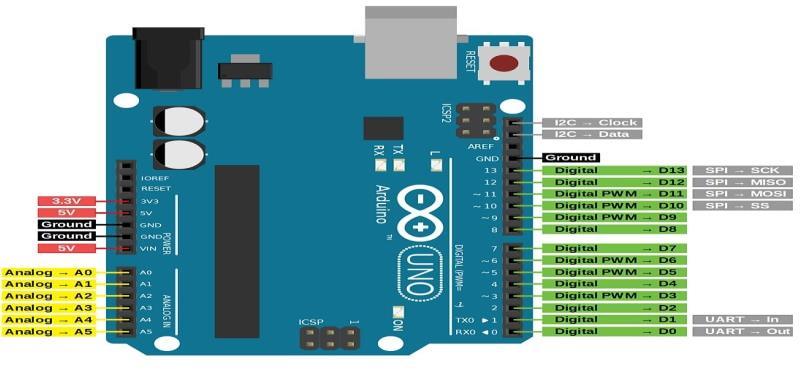
4.1 Arduino Uno:
The Arduino Uno microcontroller is selected for its accessibility, programmability, and cost-effectiveness. It receives analog voltage data and controls the relay modulebasedonthemeasuredvalues.
•Functionality:
The Arduino code sets voltage thresholds (e.g., 200V–240V for safe operation) for both overvoltage and undervoltageconditions.
The voltage sensor continuously measures the incoming AC voltage and outputs an analog signal that is read by the Arduino. This analog signal is converted to a voltage value by mapping the sensor’s input range. If the voltage exceeds the overvoltage threshold or falls below the undervoltage limit, the Arduino initiates a relay control sequence to disconnect the load. Disconnecting the load toprotectitfromdamage.
4.2 Relay Module:
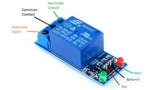
Relay modules are commonly used for load protection in voltage regulation systems, allowing a microcontroller to control power to a load based on voltage conditions. A single-channel relay module is used to connect or disconnecttheload.TherelayistriggeredbytheArduino, whichcontrolsitsstatebasedonvoltageconditions.
•Functionality:
The Arduino sends a digital signal to the relay module. When the signal is HIGH, the relay closes, connecting the load to the power supply. When the signal is LOW, the relayopens,disconnectingtheload.
This mechanism provides a fast response to voltage fluctuations, ensuring that appliances are disconnected promptlyincaseofdangerousvoltagelevels.
4.3 16x2 LCD Display:
An LCD display enhances the usability of the system by providing real-time voltage readings and alerts for the user .A 16x2 LCD module is used to display voltage readings and alert messages. It connects to the Arduino either through direct wiring or via an I2C adapter to reducewiringcomplexity.
•Functionality:
The LCD displays the current voltage level and the system’s operational status. This provides the user with instant feedback, allowing them to visually monitor voltageconditions.

International Research Journal of Engineering and Technology (IRJET) e-ISSN:2395-0056
Volume: 11 Issue: 11 | Nov 2024 www.irjet.net
Messages like “Voltage Stable,” “Overvoltage Detected,” or “Undervoltage Detected” alert users to the system’s state,enablingthemtotakeanyadditionalprecautionsif necessary.
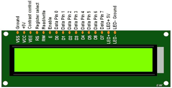
Fig-3: Pindiagramof16x2LCDDisplay
4.4 Voltage sensor (ZMPT101B):
The ZMPT101B AC voltage sensor module measures AC voltage and is used in a variety of applications. The ZMPT101B uses a voltage transformer to measure AC voltage accurately. It has an analog output that can be adjusted.
•Functionality:
The ZMPT101B voltage sensor monitors AC voltage levels and sends an analog signal to the Arduino, which interpretsthesereadings.
Based on preset voltage thresholds, the Arduino either allowsnormaloperationortriggersarelaytodisconnect the load if unsafe voltage levels are detected, protecting appliances. The real-time voltage levels are also displayedonanLCDforeasymonitoringbytheuser.
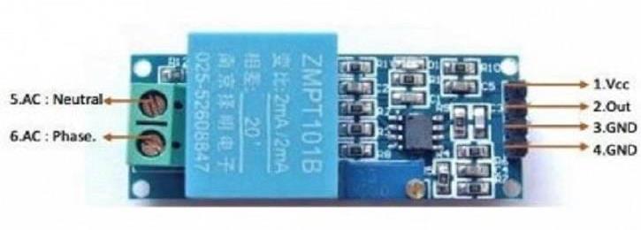
Fig-4: Pindiagramofvoltagesensor(ZMPT101B)
p-ISSN:2395-0072
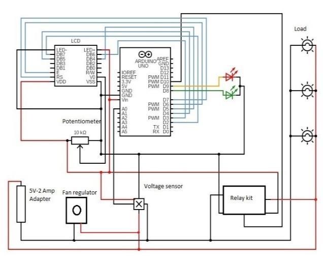
Fig-5: Circuitdiagramofproject
6. METHODOLOGY
6 1 Implementation:
• The 5V adapter provides power to the entire circuit, specifically the Arduino Uno. The adapter is connected to the Arduino's Vin and GND pins to supply 5V DC, which is also distributed to other componentsasneeded.
• The Arduino Uno acts as the control unit in this system, receiving input from the voltage sensor (ZMPT101B),processingit, andcontrollingthe relay module and LEDs. It uses analog and digital pins to interfacewiththevariouscomponents.
• The ZMPT101B sensor is a specialized module for measuring AC voltage. It provides an analog signal output proportional to the AC voltage it measures. Connect the output of the ZMPT101B to one of the Arduino’s analog input pins (e.g., A0). The ZMPT101B has power and ground pins, which are connectedtotheArduino’s5VandGNDrespectively.
• The 16x2 LCD Display shows real-time voltage readingsandstatusmessages(suchas“SafeVoltage,” “Overvoltage,” and “Undervoltage”). VSS and VDD pins of the LCD connected to GND and +5V from the Arduino. RSandEpinsontheLCDareconnectedto digital pins (D12 and D11, respectively) on the

International Research Journal of Engineering and Technology (IRJET) e-ISSN:2395-0056
Volume: 11 Issue: 11 | Nov 2024 www.irjet.net
Arduino for controlling the data flow. D4-D7 on the LCDareconnectedtotheArduino’sdigitalpins(e.g., D5-D8).
• The V0 pin of the LCD is connected to the middle terminalofa10kOhmpotentiometer.Theothertwo terminals of the potentiometer are connected to 5V and GND, allowing the user to adjust the display contrast. This potentiometer is used to adjust the contrastoftheLCD.
• The relay module is used to control the connection to the load (bulbs). It acts as a switch, which the Arduino controls based on the voltage level. The signal input of the relay is connected to one of the Arduino’sdigital output pin. The powerand ground pins of the relay is connected to the Arduino’s 5V and GND. The bulbs is connected to the normally open (NO) terminals of the relay, allowing them to be turned on or off depending on the voltage conditions.
• The load in this setup consists of three bulbs connected in parallel. Each bulb is mounted in a holder.
• Two LEDs provide a visual indication of the system status.GreenLEDindicatesthatthevoltageiswithin asaferange.RedLEDlightsupwhenanovervoltage or undervoltage condition is detected. The green LEDisconnected toone digital outputpin(e.g.,D6) on the Arduino with a current-limiting resistor (typically 220 ohms) to ground. The red LED is connected to another digital output pin (e.g., D5) withasimilarcurrent-limitingresistortoground.
• The fan regulator in the diagram may help stabilize the AC voltage feeding into the voltage sensor, especiallyinregionswithfrequentfluctuation.
6.2 Working Process:
1. VoltageMonitoring:
TheZMPT101Bvoltagesensorcontinuouslymonitors AC voltage levels in real-time. It converts the measuredvoltageintoananalogsignal,whichisthen read by the Arduino. The Arduino processes this signal and converts it into a readable voltage value, whichisthendisplayedontheLCD.
2. VoltageComparison:
The Arduino compares the measured voltage against preset safe thresholds for overvoltage and undervoltage conditions. These thresholds define the safe operational range, protecting the connected load fromextremevoltagefluctuations.
3. RelayControl:
p-ISSN:2395-0072
OvervoltageorUndervoltageConditions:Ifthevoltage is above the overvoltage limit or below the undervoltage limit, the Arduino outputs a LOW signal to the relay. This LOW signal causes the relay to disconnect the load (e.g., bulbs), preventing potential damage. Normal Voltage Range: When the voltage is within the safe limits, the Arduino keeps the relay HIGH,ensuringtheloadremainsconnected.
4. LEDIndicators:GreenLED:
Lights up when the voltage is within the safe range, indicatingnormaloperation.RedLED:Lightsupwhen the system detects an overvoltage or undervoltage condition,signalingafaultinthevoltagelevels.
7. RESULTS AND DISCUSSION
The system was tested under various simulated voltage conditionstoevaluateitseffectivenessindetectingunsafe voltage levels and responding appropriately. Table 2 illustrates the system’s response to different voltage conditions,highlightingitsreliabilityandresponsetime Voltage
TABLE-2: SystemResponsetoVoltageConditions
Normal Voltage Load Connected - "VoltageStable"
Overvoltage Load Disconnected <500 "Overvoltage Detected"
Undervoltage Load Disconnected <500 "Undervoltage Detected"
The system consistently demonstrated prompt disconnection of the load during overvoltage and undervoltage conditions. This ensures that household appliances remain protected, confirming the system’s efficacyandreliability.
• Analysis
The system’s performance was evaluated based on accuracy,responsetime,anduserinterfacefunctionality. The Arduino-based design proved to be a cost-effective solution with rapid response times, disconnecting the load within 500 ms of detecting unsafe voltage levels. Additionally, the LCD display improved usability by providing clear, real-time information on the system’s status,makingitsuitablefordomesticuse.

International Research Journal of Engineering and Technology (IRJET) e-ISSN:2395-0056
Volume: 11 Issue: 11 | Nov 2024 www.irjet.net p-ISSN:2395-0072
In conclusion, the successful implementation of an overvoltage and undervoltage load protection system which provide safety to electrical equipment from potential damage caused by voltage fluctuations in the power supply. This project hasindicate the effectiveness of a circuit designed to detect and respond to both overvoltage and undervoltage conditions. By utilizing a voltagesensorandarelaymodule,thesystemaccurately monitors the input voltage and disconnects the load wheneveritexceedspredefinedthresholds.Theproject's outcomes highlight the importance of reliable power protection,especiallyinregionsinclinedtopowersupply irregularities. Overall, this project serves as a solid foundation for developing robust and intelligent power protectionsystems,contributing to the overall reliability andefficiencyofelectricalinfrastructure
[1]"Design and Implementation of an Automatic Over/Undervoltage Protection System for Single-Phase Low Voltage Power Lines ",Derek Ajesam Asoh,31 Dec 2021
[2]Wang Yu, "Undervoltage protection system, undervoltage protection circuit and switching power supply"22Jul2019
[3]Peng Zheng “Low-temperature drift overvoltage protectionsystem”,07Dec2020
[4]Chithras Thangavel,"Modern Voltage Stability Monitoring Based on Arduino and Alert Through MessagingService",26Nov2023
[5]P. Umapathi Reddy, "Monitoring and control of singlephase electrical systems using lot based microcontrollers", 31 Oct 2022- International Journal of Reconfigurable&EmbeddedSystems(IJRES)
[6]Gao Hong, "Overvoltage protection circuit and overvoltageprotectioncontrolmethod",06Sep2017
[7]Brown, L., et al., "Microcontroller Applications in Domestic Voltage Regulation," International Journal of ElectricalSystems,vol.8,no.2,pp.123-130,2021.
[8]Smith, J. and Kumar, R., "Using Arduino for Real-Time ElectricalMonitoringinHouseholdAppliances,"Journalof EmbeddedSystems,vol.15,no.4,pp.203-211,2020
[9]Jones, A., "Low-Cost Voltage Protection for Domestic Applications," Electronics & Safety Review, vol. 12, no. 3, pp.78-85,2019.