26 minute read
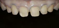
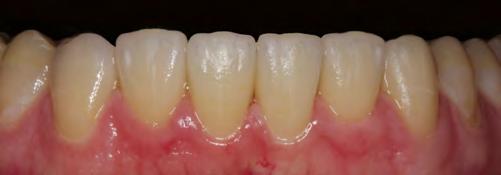
Adhesive cementation of the restorations in the upper


07b
Advertisement
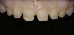
07d
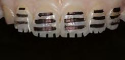
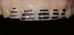
07 — The individual minimally invasive preparation steps in the upper anterior teeth 07e 07f
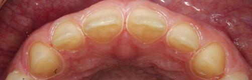
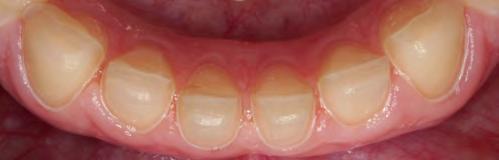
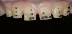
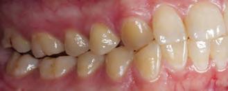
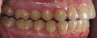
08 — Completed preparation of the upper and lower anterior teeth (partial preparation) 08b
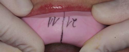
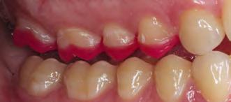
Step 5: The mock-up was removed and the labial enamel was cut away until the markings were no longer visible. The cervical areas of the teeth were prepared along the gingival margin. The palatal preparation depth was between 0.3 and 0.5 mm. In the areas where the enamel loss on the palatal surface extended beyond the tubercle, we prepared the teeth for a 360° veneer. This was done to prevent palatal fractures from occurring.
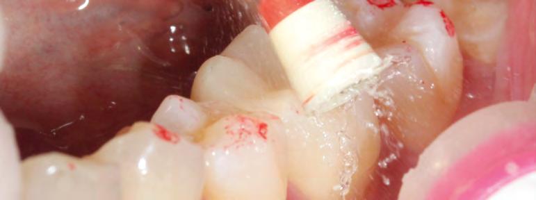
Step 6: Before we finely contoured the margins, we placed a #000 retraction cord. The teeth were prepared with a red contra-angle handpiece at reduced speed (40,000 rpm) up to the level of the retracted gingiva. This preparation step can be done with air cooling.
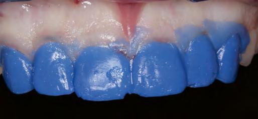
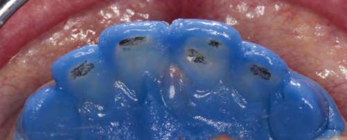
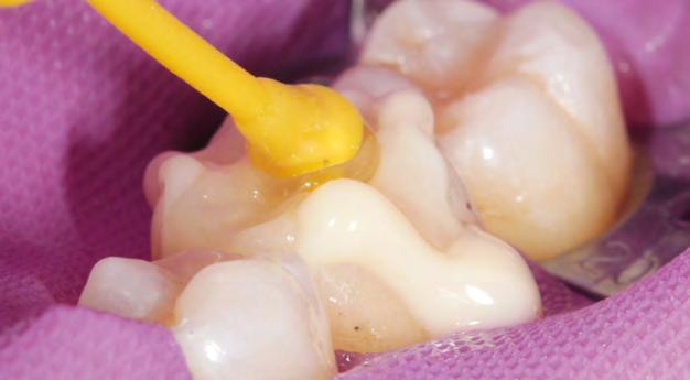
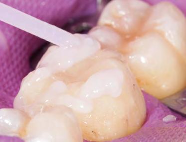
A silicone matrix, which was produced on the basis of the diagnostic wax-up, was filled with hydrocolloid. Alternatively, the thermoforming method could have been used to make a mould of the wax-up, which would have been filled with silicone impression material. This enabled us to check whether or not we had removed enough of the tooth structure (Fig. 9). If the hydrocolloid is less than 0.3 mm thick, the tooth structure that needs to be further reduced is marked with a wax pencil.
After this impression step, a model was produced with a fast-setting stone (Whip Mix Snap-Stone) in order to check the prepared surfaces. The silicone matrix (diagnostic wax-up) was given to a specialized dental assistant who fabricated the indirect provisional restorations.
Preparation of the lower front teeth and fabrication of the model
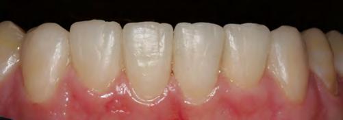
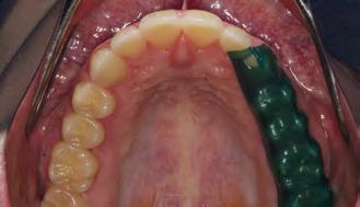
The lower front teeth were prepared and checked in the same way as the upper front teeth. The preparation depth was not to exceed 0.3mm. Before the impressions were taken, a #0 cord (soaked with ViscoStat Clear, Ultradent) was placed over the #000 cord. It was removed shortly before the impression material was inserted. The #000 cord keeps the sulcus open and dry during the impression taking process. We took an overall impression and two partial impressions for the reconstruction of the individual teeth. The articulator was programmed with all the necessary movement data of the lower jaw.
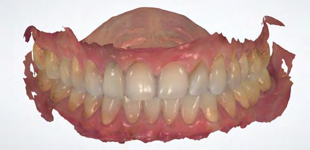
The dental technician produced a wax-up of the front teeth using an esthetic wax. This allowed the dental technician, the dentist and the patient to jointly examine the phonetic, functional and esthetic properties of the restoration (Fig. 10). The adjustments were made with the consent of the patient. Subsequently, the wax-up was invested and then the restoration was pressed.
The final appearance of very thin veneers and crowns is considerably dependent on the colour of the remaining tooth structure. Therefore, the colour of every single prepared tooth was determined. Furthermore, the dental technician produced individual dies with the corresponding shade in the dental lab (IPS Natural Die Material).
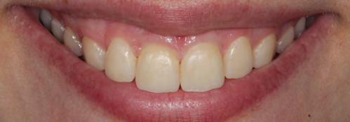
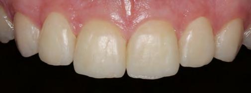
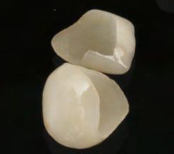
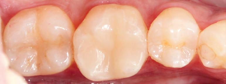
The lab-fabricated crowns were characterized before they were tried in. This allowed the phonetic, functional and esthetic properties of the teeth to be checked and documented by means of photographs taken with a smartphone. After the necessary adjustments had been made, the restorations were glaze fired. The completed restorations (360° veneers/partial crowns) measured between 0.3 and 0.5 mm in thickness (Fig. 11).
Adhesive cementation
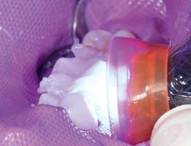
If possible, a rubber dam should be used to establish a dry working field for the adhesive cementation technique. Alternatively, a #00 retraction cord should be placed in the sulcus before the cementation procedure in order to make the preparation margin easily accessible (Fig. 12). In the present case, the neighbouring teeth were isolated with Teflon tape. We usually place the crowns in pairs. In this case, after etching with 37 % phosphoric acid, the entire preparation was shown to be located in the enamel tooth structure. Dentin was visible in individual areas, where it had been exposed due to the parafunctional habits of the patient.
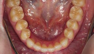
The upper and lower front teeth as well as the lower posterior teeth were permanently restored. A few minor adjustments still needed to be made on the occlusal surfaces of the temporary upper restoration.
10a
10b
10 — Wax-up for the examination of the phonetics, function and esthetics 10c
11a
3rd treatment phase: permanent upper posterior restoration 11b
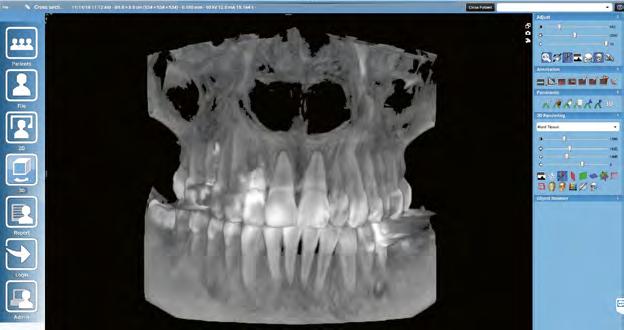
We removed the indirect restorations in the upper posterior region and took impressions of both jaws. A centric jaw relation record was made using thermoplastic sticks (GC Bite Compound, GC). The upper jaw model was positioned in the articulator on the basis of an arbitrary facebow record. With the help of the two thermoplastic bite records, the lower jaw model was mounted in the articulator in a joint-related orientation.
Application of ReFu wax
We fabricated the upper partial crowns with ReFu wax (Reference Function wax, Keydent). Initially, this wax was very hard. As a result, we were able to check the contact points after the placement of the crowns with the help of Shimstock contact foil. In the oral environment, the wax became softer. We asked our patient to make certain forceful
11 — Try-in of the restoration after the stains firing cycle 11c
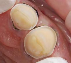
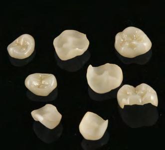
movements, some of which simulated parafunctions (Fig. 13). If a cusp interfered, this was shown on the chewing surface and the necessary adjustments could be made. Subsequently, the waxed-up models were invested and the monolithic partial crowns were fabricated using lithium disilicate (IPS e.max Press) in the press technique. The restorations were characterized and glazed (Fig. 14). No adjustments were necessary after the restorations had been adhesively bonded. The thickness of the posterior partial crowns measured about 0.5mm on average.
Adhesive cementation
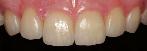
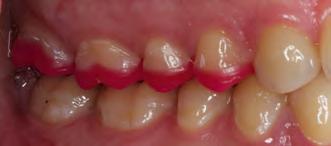
A rubber dam was placed and the neighbouring teeth were protected with Teflon tape. Then the posterior partial crowns were seated in pairs on the prepared upper teeth using the adhesive cementation technique (Fig. 15). After the restorations had been cemented in the patient’s mouth, we checked the dynamic occlusion with the help of Occlusal Indicator Wax (Kerr) (Fig. 16). The wax did not show any premature occlusal contacts.
IPS e.max Press – why is it the gold standard?
Biocompatible Biomimetic Minimally invasive Extremely strong Long-lasting; hardly any failures after 25 years Excellent conversion of wax-ups into ceramic crowns Easy to use Easy to colour High accuracy of fit Controlled function, also in bruxers Affordable costs: glazed monolithic crowns One material for virtually every indication
13 — Examination of the static and dynamic occlusion with ReFu wax 13b
14 — The pressed ceramic restorations prior to placement 14
17a 15 — Ceramic partial crowns seated with the adhesive technique 15a 15b
17b
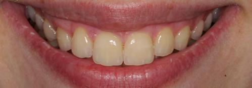
The patient was given a Brux Checker foil and instructed to use it for two nights (Fig. 17). This allowed us to make sure and record that the restorations were free from any interference during sleep and bruxing. In most cases, no subsequent grinding adjustments are necessary.
Summary
Minimally invasive restorations measuring 0.3 to 0.6mm in thickness placed with the adhesive technique have shown to be a reliable treatment option in our practice. We have been
Dr Diether Reusch Jan Strüder, Dentist Praxis für Zahnmedizin Neustrasse 30 56457 Westerburg Germany
working with the described method since 1993. Particularly in young patients showing a substantial loss of enamel, we know of no other comparable long-lasting and minimally invasive treatment approach.
Note
Ivoclar Vivadent does not recommend that IPS e.max Press and IPS e.max CAD are used in patients with bruxism. Nevertheless, our experience has shown that if all the functional and parafunctional aspects are properly considered, no complications are to be expected in bruxers.
Paul Gerd Lenze, MDT Sascha Fasel, DT Synthese Dentallabor 56457 Westerburg Germany
How durable are IPS e.max Press and IPS e.max CAD restorations?
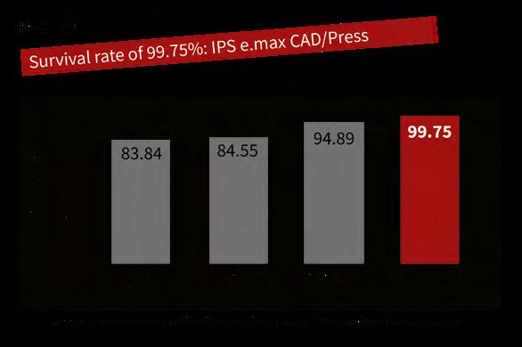
In a study by K. A. Malament, IPS e.max ® CAD/Press performed the best out
of all the dental glass-ceramics tested, with a survival rate of 99.75% over a period of just more than ten years.
Within the framework of this study, 6000 all-ceramic restorations have been placed since 1983. Four different types of ceramics have been evaluated - Dicor/Dentsply Sirona (n = 1504) - In-Ceram/Vita (n = 330) - IPS Empress (n = 2133) - IPS e.max Press or CAD (n = 2364)
Records for Dicor have been kept since 1983, for In-Ceram since 1990, for
IPS Empress ® since 1992 and for IPS e.max since 2005.
View Scientific Report online
Surpassed expectations
Despite the shortest observation period of just over ten years (128 months), lithium disilicate restorations made of IPS e.max Press and IPS e.max CAD showed the highest survival rate of 99.75% in this large scale survey. According to K. A. Malament the materials fulfilled and even surpassed all the clinical practice requirements.
Source: IPS e.max, Scientific Report, Vol. 03/2001-2017
Clinical data confirms success
The performance of IPS e.max has been scientifically monitored since the inception of the product. The study results of notable experts from around the world have contributed to the compilation of an excellent data base. The average survival rate for both lithium disilicate and zironium oxide is 96 %. The IPS e.max Scientific Report contains a summary of all the available in vivo and in vitro study results.
Easy and efficient: Composite resin blocks for the CAD/CAM technique
Single-tooth restorations with Tetric CAD A report by Dr Hidetaka Sasaki, Tokyo, Japan
Composite blocks for CAD/CAM applications are on the rise, partic - ularly for producing small restorations, such as inlays, onlays and occlusal veneers. And quite rightly so, for this type of material has a lot to offer: it exhibits sound mechanical properties combined with an extraordinary grinding accuracy and it is easy and efficient to process in day-to-day procedures.
The following clinical report describes the workflow to create an esthetic single-tooth restoration using the new Tetric CAD ® composite block. The blocks are available in two degrees of translucency – HT and MT – and in a variety of shades. They exhibit a pronounced chameleon effect to provide restorations that blend in well with the optical characteristics of the surrounding residual tooth structure. The material can be polished to a high gloss in a few seconds both intraorally and extraorally. In addition, it can be easily repaired intraorally with conventional composite resins.
Clinical case
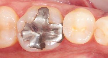
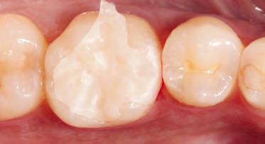
The pre-op showed a defective amalgam filling on tooth 36 in the lower posterior region. The filling needed replacing (Fig. 1). The indication for a multi-surface inlay was given. It was the patient’s wish to have an esthetic, i. e. tooth-coloured restoration. We decided to opt for the Tetric CAD composite blocks. This material is part of the portfolio of Ivoclar Vivadent blocks and is suitable for permanent single-tooth restorations. It is supplied in industrially processed, pre-cured blocks that exhibit superior strength and a higher filler content than direct restoratives. Because they have undergone an industrial polymerization process, shrinkage stress is not an issue with Tetric CAD.
Designing the restoration
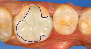
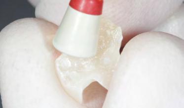
Shade selection is performed on the natural dentition, primarily on the neighbouring teeth. We decided to use shade HT A2. The HT blocks are a good choice, particularly when it comes to producing fairly small restorations such as inlays as they provide a pronounced chameleon effect. Once the old amalgam was removed, the tooth was prepared in line with the recommended preparation guidelines (Fig.2). Then, an optical impression was taken using an intraoral scanner and the inlay was designed in the CAD module (Fig. 3). Subsequently, the restoration was ground from the block.
Grinding times are considerably shorter for CAD/CAM composite resins compared with other materials. Although the composite is softer to grind, the restoration is not affected by this. It only means that the grinding tools are less quickly worn and offer a long service life, maximizing the cost efficiency of the practice.
Composites are “flexible” materials. Their modulus of elasticity is similar to that of dentin. High flexural strength provides adequate resistance and stability. Given their low brittleness, composites can be ground to exhibit highly homogeneous surfaces and to obtain accurate, thinly tapered margins without loss of strength. Marginal chipping or crack formation are unlikely to occur.
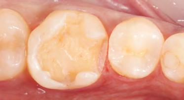
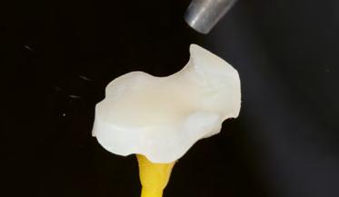
In the present case, a try-in was performed immediately after the grinding process to check the fit of the inlay with the natural residual tooth structure (Fig.4).
Conditioning the restoration
The attachment point was easy to smooth out with fine-grit
diamonds. This was followed by extraoral polishing using
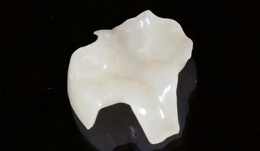
composite polishers (e. g. OptraPol ® ) (Fig. 5). Particularly note
worthy was the speed with which the restoration was polished to a high gloss. It only took a few seconds to achieve a glossy surface (Fig.6). Composites do not require an additional glaze firing cycle. This has a positive effect on the time resources of the practice.
It is essential to condition and pre-treat the bonding surface correctly. This requires the use of an adhesive system that is appropriate for this type of material to ensure the longevity of the restoration. The manufacturer’s instructions should be followed at all times.
In the present case, the bonding surface of the inlay was air-blasted with aluminium oxide (50–100 μm) at a pressure of 1–1.5 bar, followed by thorough rinsing (Fig. 7). The restoration can be cleaned either in an ultrasonic unit or with a steam cleaner. It is recommended to additionally clean the restoration with 70% ethanol to disinfect it. Pre-treating the restoration in this way is mandatory for
02
04 01 — Preoperative situation: defective amalgam filling on tooth 36
02 — Prepared tooth
03 — Designing the inlay in the CAD module
04 — Checking the fit and shade match of the inlay after the grinding process
Tetric CAD because air-blasting increases the surface area and creates a retentive pattern that acts as a basis for the adhesive cementation. Pre-treating therefore ensures a reliable bond between the luting material and the restoration.
To condition the restoration, Adhese ® Universal adhesive was applied and
scrubbed into the pre-treated bonding surface for 20 seconds using a micro
brush (Adhese Universal is also available in the VivaPen ® delivery system for
direct applications). It is important to observe the recommended agitation time to ensure that the adhesive can penetrate sufficiently (Fig. 8). Excess material is carefully dispersed using compressed oil-free air until a glossy immobile film results. Pooling must be avoided.
It is not necessary to light-cure the adhesive at this point: the adhesive will be cured together with the luting composite when the inlay is placed on the tooth.
06
08 05 — Extraoral polishing with OptraPol
06 — Restoration after high-gloss polishing
07 — Air-blasting the bonding surface with 50–100 μm aluminium oxide at 1–1.5 bar; followed by cleaning
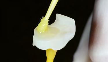
08 — Scrubbing Adhese Universal into the bonding surface for 20s, followed by drying with air
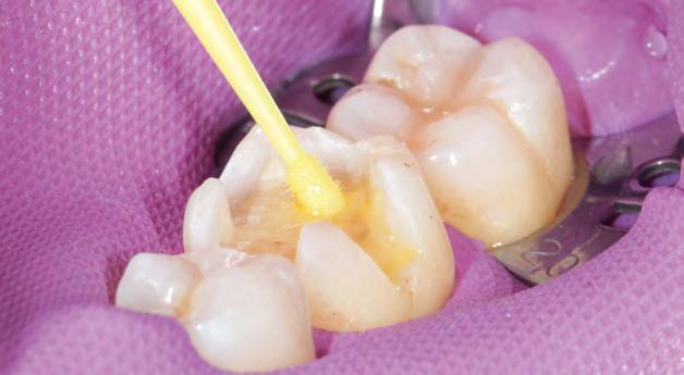
Adequate isolation of the operating field is required for reliable bonding. The tooth preparation was cleaned and then conditioned, rinsed and dried using a conventional etch & rinse procedure. Adhese Universal adhesive was scrubbed into the tooth structure for 20 seconds and then dispersed (Fig.9). The adhesive was then light cured for 10 seconds using the Bluephase Style curing light (Fig. 10). According to the manufacturer’s recommendation, a curing light emitting a light intensity of least 500 mW/cm 2 should be used for this step.
Placing the restoration
The inlay was seated using Variolink ® Esthetic luting composite. The luting composite was applied directly from the syringe onto the bonding surface and then the inlay was seated and retained in position applying light pressure (Fig.11). Variolink Esthetic is particularly well suited for this step because excess material can be removed from the cement line with ease and it does not cause a “buffering effect” as is often the case with harder luting composites (Fig. 12). Tack-curing from all sides for 2 seconds facilitates the clean-up process. The cement line should be covered with air block gel (e. g. Liquid Strip) to prevent the formation of an oxygen inhibition layer (Fig. 13).
At the final curing stage, the adhesive on the bonding surface and the luting composite are cured togehter (exposure time: 10 seconds per mm of composite and segment). It is recommended to use a curing light that produces a light intensity of at least 1,000 mW/cm 2 for this step.
At this stage, the adhesive and the luting composite applied to the bonding surface are polymerized by the light passing through the restoration. In the process, a reliable adhesive bond forms. Upon completion of the light-curing step, Liquid Strip can be rinsed off (Fig. 14).
09 — Conditioning the prepared tooth with Adhese Universal for 20 s, followed by drying with air
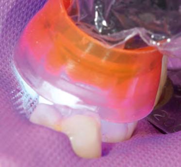
10 — Light-curing for 10 s using Bluephase Style
14 13 — Applying Liquid Strip to prevent the formation of an inhibition layer
14 — Light-curing all segments for 10 s per mm of composite using a Bluephase Style
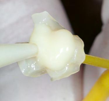
15 — Occlusal check followed by intraoral polishing with OptraPol
16 — Inlay in situ: great optical integration thanks to chameleon effect
Finishing and outcome
An occlusal check was carried out and any interferences were removed using fine diamonds. In the present case, final intraoral polishing was performed with the OptraPol polishers (Fig. 15).
This procedure resulted in a highly esthetic single-tooth restoration. Because of the chameleon effect, the inlay blends seamlessly into the surrounding natural tooth structure (Fig. 16).
Conclusion
Highly esthetic permanent single-tooth restorations can be achieved with the composite blocks of the Tetric CAD range in really short times. The guidelines for the adhesive technique need to be observed and a coordinated luting system must be used.
Easy and rapid processing and polishing procedures and the possibility for effecting intraoral repairs, similar to conventional filling composites, enable a highly efficient treatment workflow and increase the efficiency of day-to-day procedures in the dental practice.
Dr Hidetaka Sasaki es Dental Office 1F, 3-9-14 Kudanminami, Chiyoda-ku Tokyo Japan www.es-dental.net
Preoperative digital planning
RAW workflow: A professional’s approach to planning monolithic restorations on single-tooth implants A report by Florin Cofar, DDS, Timisoara/Romania, and Dr Eric van Dooren, Antwerp, Belgium
Digital planning and preparation provides a high level of reliability in implant-prosthetic procedures. Preliminary virtual simulation of the surgical intervention can provide the necessary confidence and certainty to carry out the actual surgery with peace of mind. Two dental professionals describe their procedure.
Every workflow begins with an information gathering exercise. If a digital workflow is followed, the information consists of data that can be processed by the software being used. Our prosthetics team employs a photo-video protocol to examine the esthetic-functional relationship between the smile, dental situation and face of the patient. In addition to conventional photographic documentation and video sequences, we use digital volume tomography (DVT) and intraoral scans in the assessment of implant prosthetics cases. By merging all the information gathered we obtain what we call a “digital clone”. These amalgamated data sets enable us to plan all steps in a virtual treatment suite as if we were working on a clone of the patient. Below we present our procedure, using the example of an implant prosthetic single-tooth restoration.

02
01 — Portrait image prior to the intervention
02 — DVT data set in the software program
04 — Virtual extraction of the tooth in need of treatment
05 — Designing the drill template
06 — Digitally designed alveolar cavity with scan body
05
06
Creating a digital clone
The process begins by obtaining a highquality portrait photograph, a DVT and an STL file (Figs 1 to 3). In the case presented here, tooth 12 can no longer be preserved and needs to be replaced with an implant prosthetic restoration. Designing the prosthetic restoration forms the first stage of the implant planning sequence. In the present case, the shape of the existing tooth should be maintained. If an analogue workflow is followed, the premise for the implant is the extraction of the tooth. This scenario also forms the first step in the digital procedure described here - however, the tooth is “only” extracted virtually. We can extract the tooth digitally to design e.g. the future alveolar cavity (emergence profile) and generate an optimized emergence profile. An alveolar model is required for: 1) designing the drill template (navigated implant insertion) and 2) fabricating a temporary restoration / abutment prior to the surgical intervention.
We only ever use copies of the data files. The original data sets remain untouched. Several methods can be employed to perform the virtual tooth extraction. In our opinion, the most effective approach is to use the “Provisional Pontic” CAD process and to design the alveolar cavity to have an optimum shape. You should always work on two levels when executing this step. The working scan represents the first level. The original scan with the tooth represents the second level in this scenario.
Implant prosthetic planning
The implant crown is designed (virtual wax-up). In the present case, the tooth being replaced serves as the template. The crown reflects the position and proportions of the original tooth. A copy of the scan file is again used as working file on which the virtual tooth extraction is performed. This allows us to go back to the original data and compare it with the working file. We define the ideal implant placement position and design the peri-implant soft tissue contours on the screen to provide an adequate emergence profile (Fig. 4). We then prepare a drill template for safe transfer of the implant position to the oral cavity. Even though most dentists are familiar with this procedure, we will briefly address the fundamentals: Basically, three data sets are required for preparing a drill template: 1) a scan showing the digitally extracted tooth, 2) a data file of the DVT, and 3) a scan showing the CAD design of the tooth being treated; in the present case, this means the original scan with the existing tooth.
At the next step, we simulate the surgical procedure on the screen. The implant is inserted digitally and then a template of the procedure is exported. The conditions of the alveolar bone can be assessed to determine the bone’s fitness for the planned procedure. If necessary, the alveolar bone may be adjusted, for instance by planning a bone transplant. Alternatively, a compromise may be made and it may be preferable to opt for a cemented restoration or a change in the design instead. We take all the major decisions at the virtual implant insertion stage. The details can then be transferred to the clinical situation by means of the drill template. The position of the implant is established with the help of the wax-up (3 to 4mm deeper). The implant angle and position should be selected so that the available bone structure can be used to optimum effect, without deviating too much from the specifications of the prosthetic restoration. In this case, the aim is to provide a screw-retained restoration. We are still using our “digital clone” to plan these steps. Once the preparatory steps have been completed, the drill template is printed (Fig. 5). In addition, the STL file of the implant model including the optimized alveolar cavity design and digital scan body (Fig. 6) are prepared to design the temporary restoration.
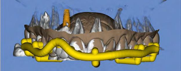
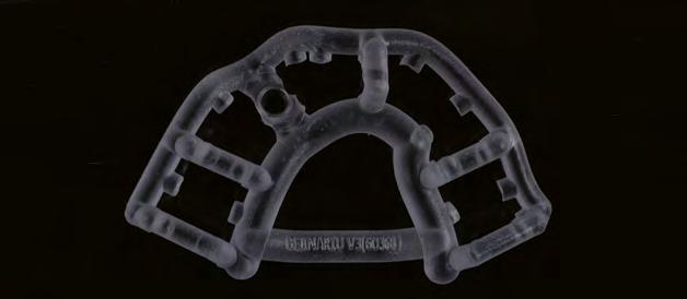
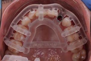
7 — Printed drill template (Mguide, MIS)
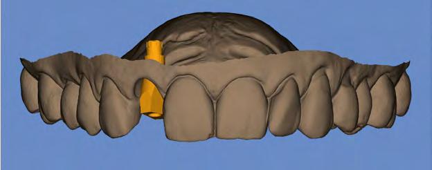
8 — Immediate temporary restoration
Designing the temporary restoration
The virtual implant model (Fig. 6) is imported into the construction software to design the abutment and/or temporary restoration. The crown-abutment interface should be placed in an optimum position in the previously prepared alveolar cavity. The Ti base has been defined at the time when the implant depth was determined during the implant planning step. In the present case, the implant has a depth of 3 to 4mm. The optimum length of the Ti base is therefore 1.5mm.
The temporary restoration is placed on a Ti base with free rotation to prevent potential problems caused by the implant index position.
Whether a screw-retained or cemented restoration is chosen is at the discretion of the dentist. We tend to prefer screw-retained restorations. However, the ultimate decision about which restoration to use can only be made at the point when the surgical intervention is planned. Whether the prosthetic restoration is made in one piece or as a hybrid crown is also at the discretion of the dentist. Hybrid restorations are normally preferred in esthetically demanding situations and onepiece restorations in the posterior region.
Surgical phase
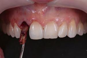
All the items required for the surgical intervention have been prepared and are now ready for use: This includes the printed drill template (Fig. 7) and the temporary implant restoration (Fig. 8). Tooth 12 is now extracted atraumatically in the “real world” (Fig. 9). Immediately afterwards, the fit of the drill
9 — Atraumatic tooth extraction
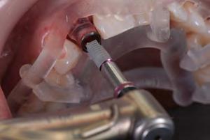
10 — Implant insertion (NP implant, MIS) with drill template
11 — Drill template and implant after insertion
12 — Temporary restoration after the surgical intervention
template is checked in the oral cavity and the implant is inserted according to the drill protocol (Fig. 10). This is followed by the augmentative measures planned in advance and finally, the temporary crown is screwed on (Figs 11 and 12).
Prosthetic restoration
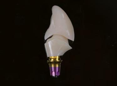
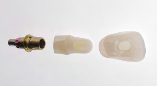
After a healing phase of at least eight weeks, the temporary restoration is removed and the design is copied. This is the first time in the entire procedure that the actual scan body is used (Fig. 13). The scan body assists in recording the position of the implant. This position corresponds to the originally planned position and also reflects the implant index position. This method ensures the accuracy of the restoration procedure. The transgingival areas have already been formed at the time of the temporary restoration. In the present case, the thickness of the gingival tissue should be additionally increased. For the final restoration, a Ti base of the same length as the one for the temporary restoration is used. This time, however, the base features an anti-rotation lock. A large selection of materials is available for the final restoration. We normally use hybrid restorations for the restoration of single implants. Here, the restoration consists of a monolithic zirconium oxide abutment (Zenostar) and a monolithic multi-shaded
13 — Clinical situation with scan body
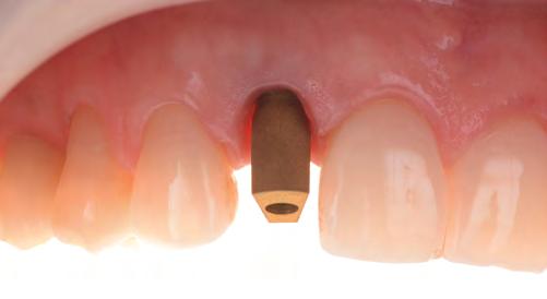
14 — Implant prosthetic restoration
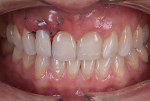
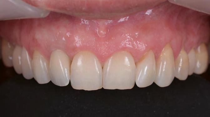
15 — Close-up of the final situation
all-ceramic crown (IPS e.max ZirCAD MT Multi). The restoration is characterized with stains and completed without any shape modifications (Figs 14 to 16).
Conclusion
Errors can be avoided by planning the intervention on a “digital clone” and preparing any auxiliary and therapeutic devices ahead of the actual surgical procedure. If this
16 — Portrait image after completion of the restoration

approach is used, suboptimal implant placement – both prosthetically and surgically – can be detected and corrected in advance. In addition, necessary augmentative measures are already evident at the planning stage and can be prepared accordingly. This way, “surprises” during the intervention on the patient can be avoided as far as possible. This brings a high level of reliability and certainty to the treatment process.
Florin Cofar, DDS S.C. DENTCOF s.r.l. Simion Barnutiu Nr 62 etj. 5 300302 Timisoara Romania Florin.cofar@dentcof.ro
Issue 01 / 2019 Teamwork Dr Eric van Dooren Tandartsenpraktijk van Dooren Tavernierkaai 2, 8e verdieping 2000 Antwerp Belgium
23
Stay up-to-date with the latest industry trends.

Find tips and tricks for your work. Learn more about top-notch innovations and dental developments. Benefit from current offers and obtain the latest information.
SUBSCRIBE NOW! www .ivoclarvivadent.com /blog www.ivoclarviv adent.com/highlights