
portfolio
Javier Haberland 2024DRAFTER FOR INTERIOR DESIGN FIRM
Luxe Design Studios 2023-current
DESIGN COMPETITION
Representative of the Pontificia Universidad Católica de Chile in the President’s Medal 2021 competition of the Royal Institute of British Architects. Project developed with the guiding professors Cecilia Puga and Paula Velasco
AUTHOR OF THE SUT CHAIR
Design developed with the guiding professors Juan Baixas and Tomás Iruarrizaga.
SUSTAINABLE MODULE IN THE NORTH OF CHILE
Project built with Gota SpA and sponsored by CRAMSA and Foundation Recrea
3
4 10 14 18
index
LUXE DESIGN STUDIOS ARCHITECTURAL DRAFTER
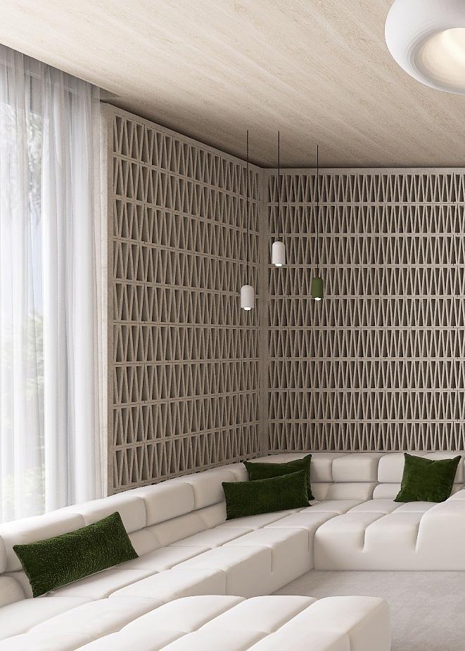
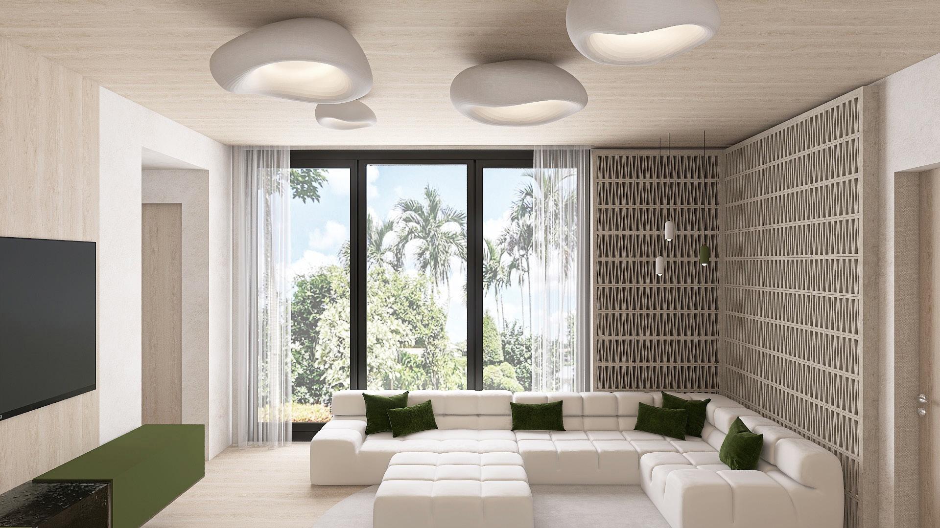
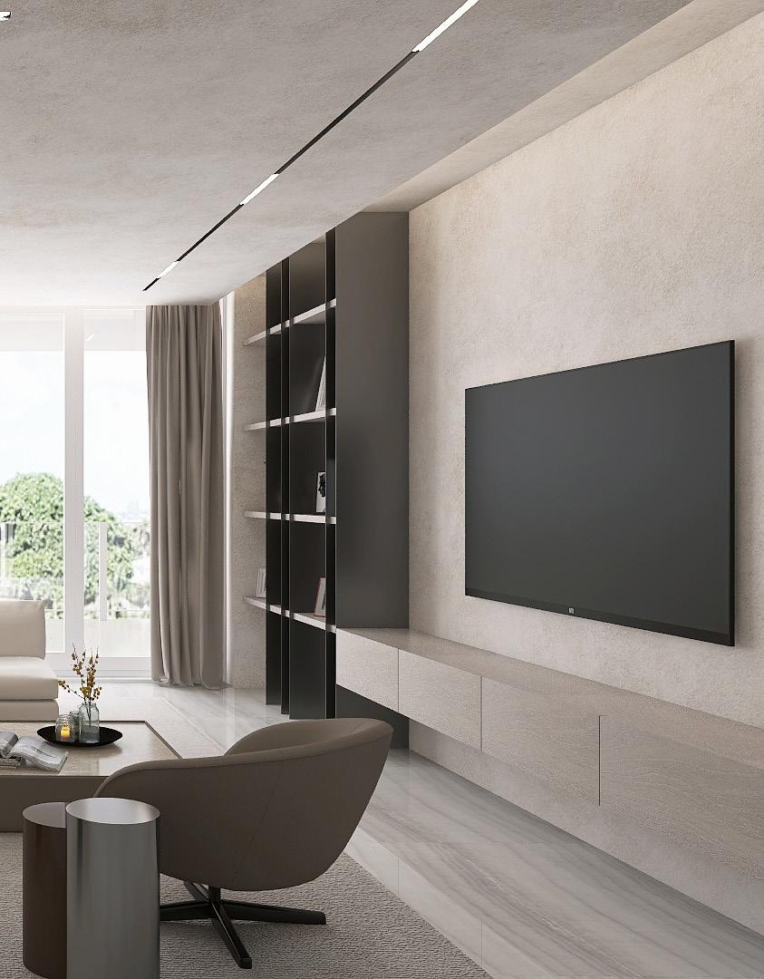
Luxe specializes in contemporary interior design, focusing on modern residential projects. The firm excels in integrating high-end furniture and lighting fixtures. As the drafter for the company, it is my responsibility to handle all documentation and oversee projects ranging from 3,500 to 14,000 square feet. Part of the job also includes producing 3D renderings for the clients and drawings for builders, millworkers and architects. Luxe takes charge of the entire process from conceptualization to selection, including light fixtures, wall finishes, flooring finishes and custom millwork.
4
1. Rendering for client’s furniture, finishes and lighting selections, 2. Window view
1. 2.
5 ID-54 FOYER / ENTRY PLAN ID-54 FOYER / ENTRY WEST WALL 2 2'-0" 6" 8'-6" 1'-2" 1'-7" 1'-6" 4'-3" 11'-0" 4'-3" TRAVERTINE WALL SAME AS OUTSIDE 6'-4" WT 23 WT 23 MI 11 FIN 51 14'-0" STORE BOUGHT MIRROR TRAVERTINE WALL SAME AS OUTSIDE 11'-0" 3.
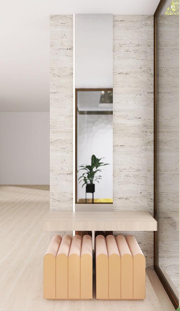
3. Elevation and rendering for client’s foyer
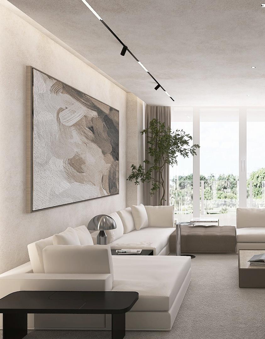
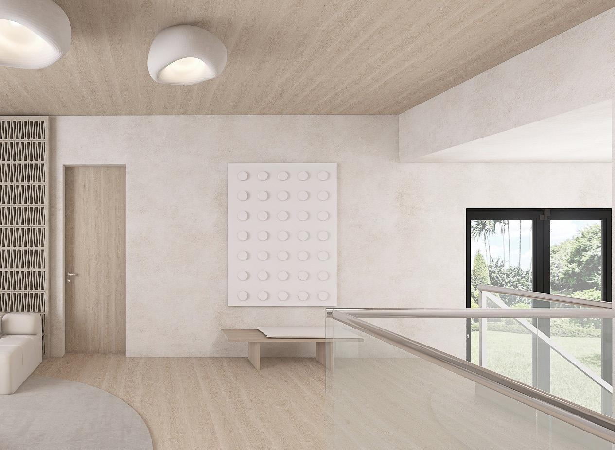
6 4. Rendering for client’s condo 4.
7
8
5.
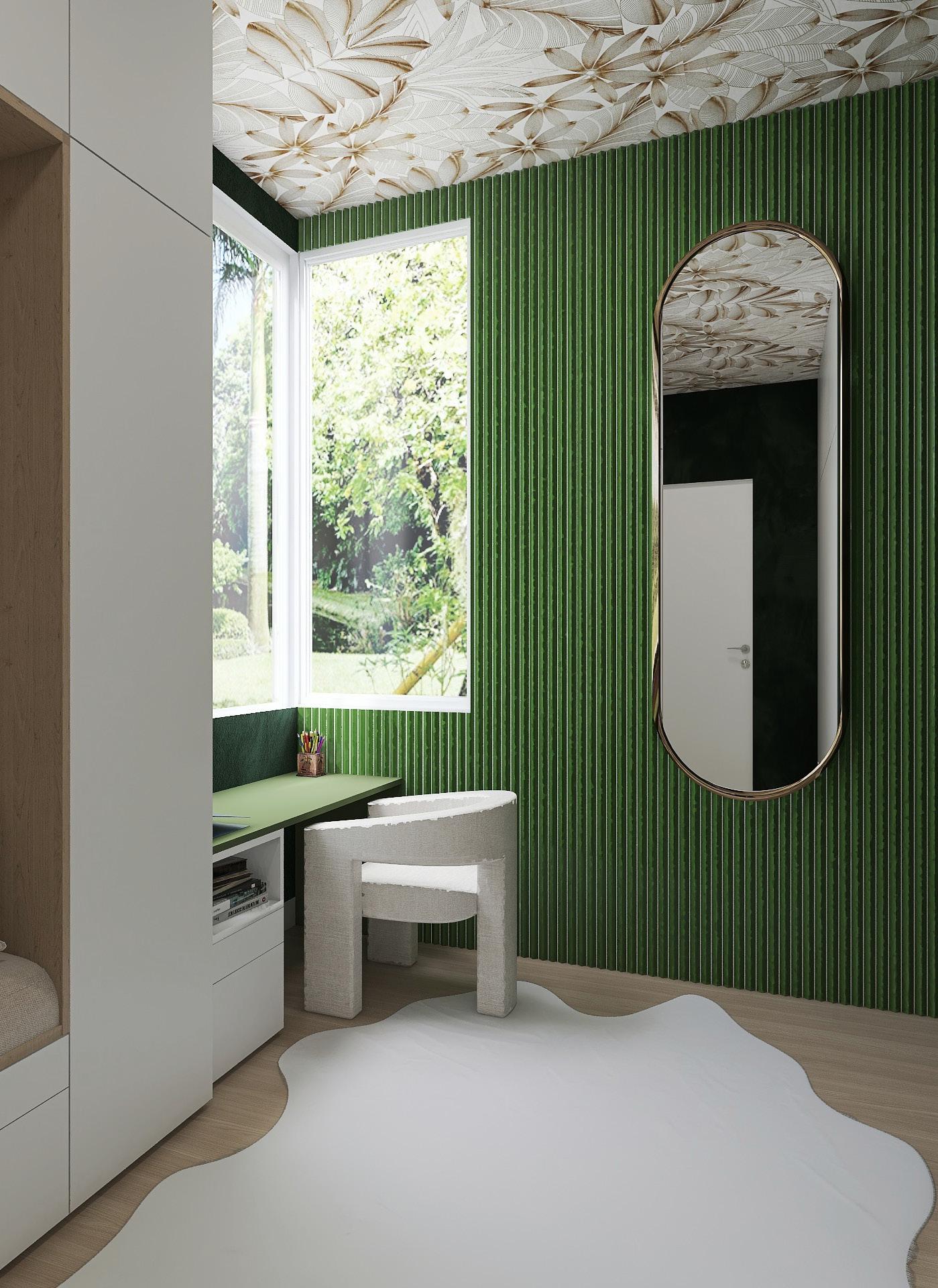
5. Rendering of client’s mudroom


9 6'-6" 3'-10" 10'-0" 8" 2" SHOWER FLOOR SLOPE DEPENDS ON DRAIN CAPACITY 1'-8" 3'-0" 6'-6" 3'-8" 4'-7" 3'-4" 1'-6" 9" 3'-9" 2" 36" DOOR 1'-6" 2'-0" 3'-0" *PLUMBING WILL REQUIRE TO ADD 4" FROM WALL (VANITIES DON'T CHANGE) *PLUMBING WILL REQUIRE TO ADD 4" FROM WALL. (VANITIES DON'T CHANGE) 2'-4" RAINHEAD 1'-6" 3'-0" 1'-6" 4'-10" 2" 5" 8" 4" 5 8 " 11" 6" 73 8 4" 4'-4" 6'-0" 2'-0" 3'-0" 3'-0" 2'-0" 3'-4" 4'-7" 2" 7" 4'-10" 7" 14'-8" 2'-4" 15'-4" 4" 4" 4" 2'-0" 2'-0" 2'-0" 4'-4" 4'-8" 4'-8" MASTER BATHROOM
PLAN SCALE: 1/2" = 1'-0" ID-16 1 MASTER BATHROOM SECTION ID-16 4 ROLLER SHADE BOX LED LIGHT POCKET DETAIL SCALE: 3" = 1'-0" ID-16 5 MV-400 BY DORR HOUZZER MASTER BATHROOM TUB ELEVATION ID-16 2 SCALE: 1/2" = 1'-0" SCALE: 1/2" = 1'-0" 6.
6. 4'-0" 11" 4'-0" 6" 6" 4'-1" 2'-6" 12'-6 2 " 2" 12'-2" 2'-0" 6'-1" 10" 6'-3" 2'-6" 2'-0" 12'-0" 9'-6" 2'-0" 2'-2" 2'-2" 2'-2" 2'-0" 2'-6" 2'-0 3 4 " 2'-11 3 4 " 2" 2'-2" 12'-0" COW
8'-8" 1'-10" 1'-10" 2'-0 3 4 " 2'-0 3 4 " BOOKCASE LIBRERO HIS OFFICE
SCALE: 1/2" = 1'-0" ID-18 2 HIS OFFICE ELEVATION SCALE: 1/2" = 1'-0" ID-18 3 7.
FLOOR
Detail and section for client’s custom bathroom, 7. Elevations for client’s lighting and furniture selections
HYDE WALLPAPER
ELEVATION
MODELS
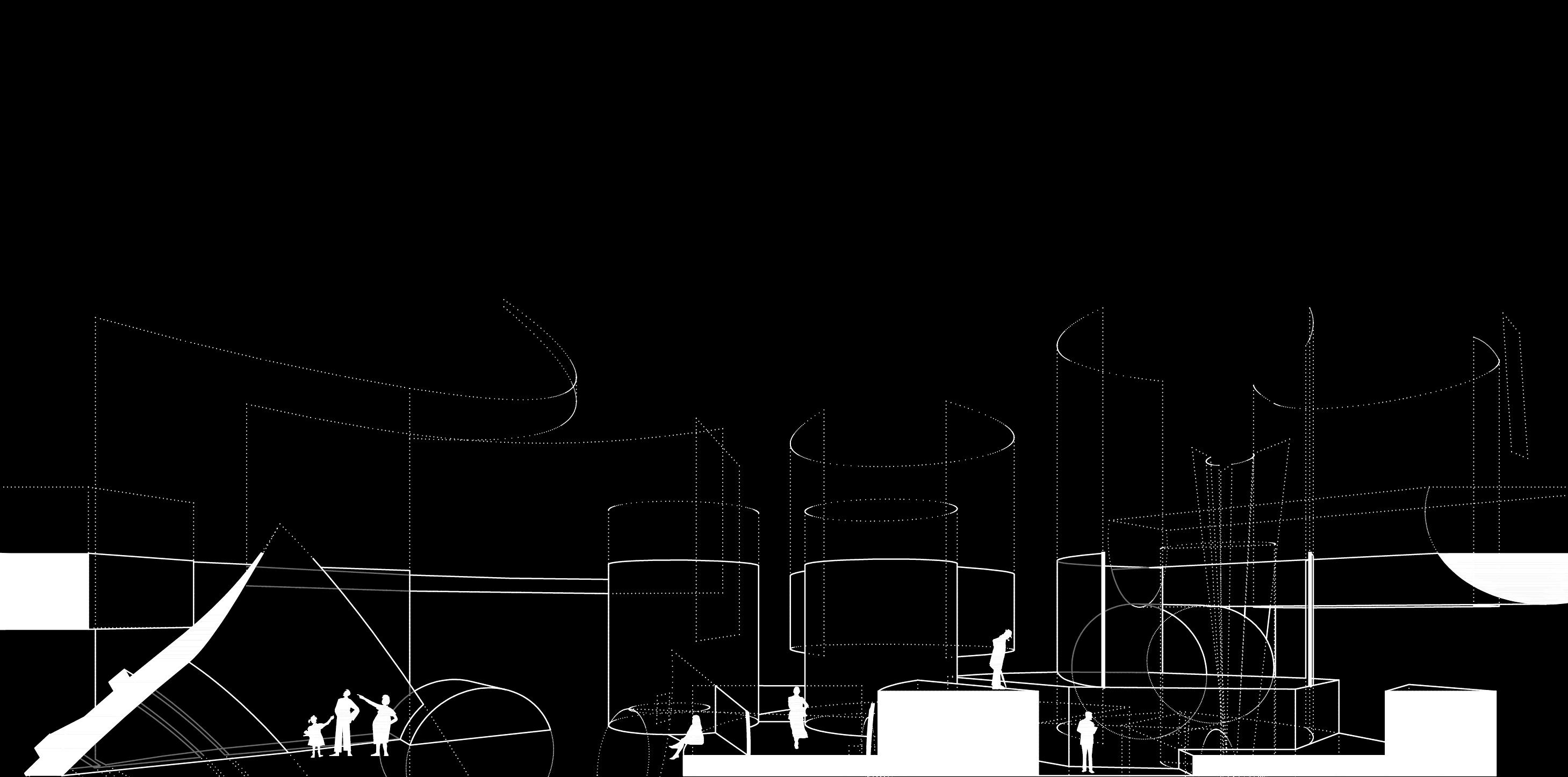
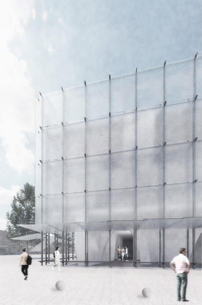
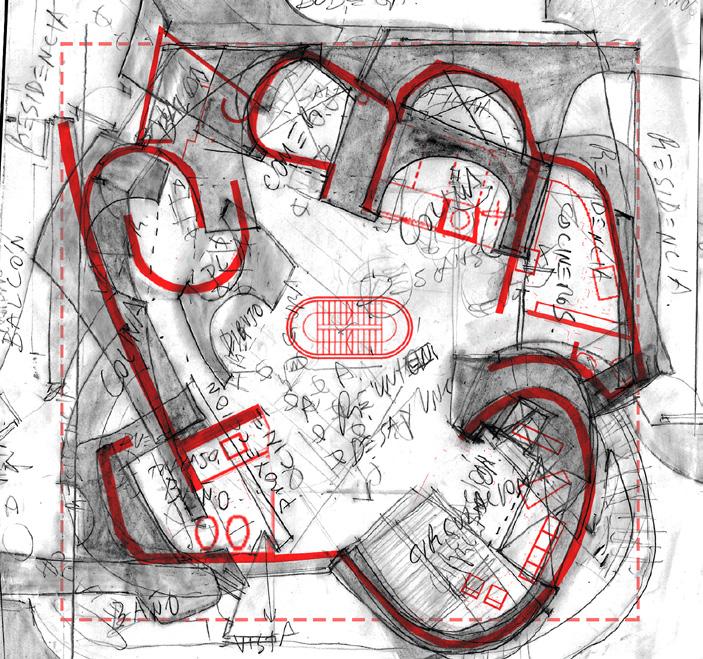
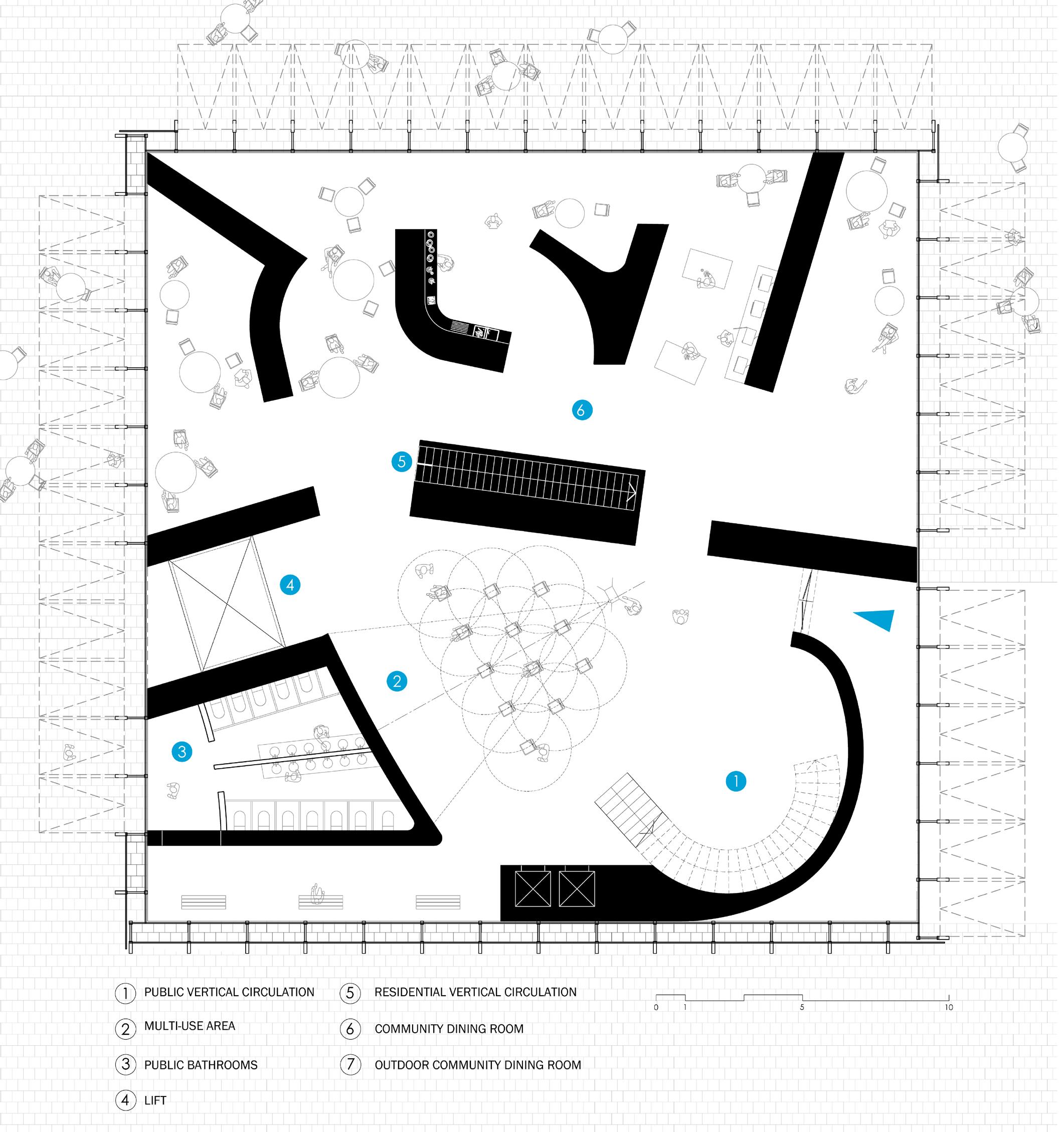
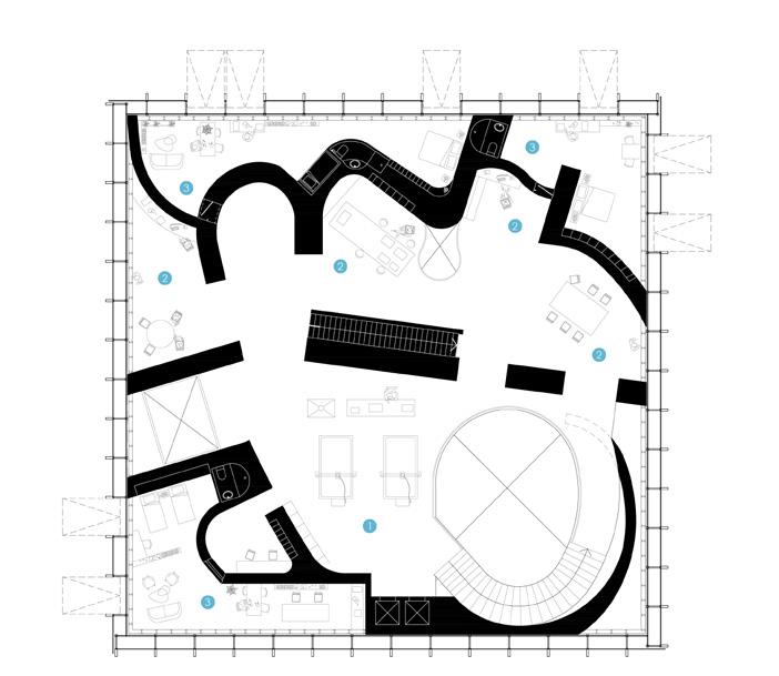
Domestic and work spaces have always been part of different worlds, but as we have seen in recent times, it is of utmost importance to begin to devise an architecture that collaborates with the coexistence of both situations.
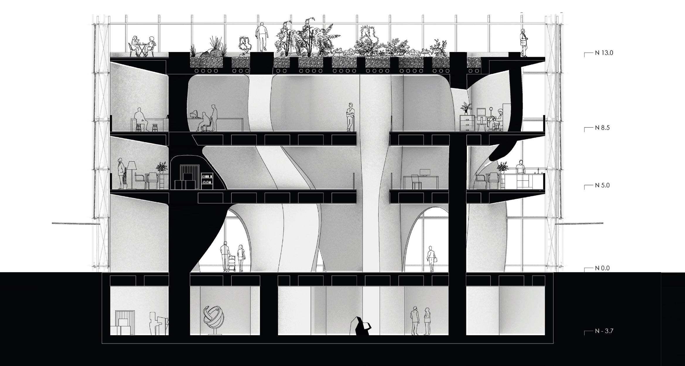
The Models Innovation Center is based on the relationship between a space for technological innovation and the residence. Privacy on the floors increases from the center to the perimeter of the building ending with the most private element, the bedrooms.
10
IN VALDIVIA
INNOVATION CENTER
1. 2.
3.
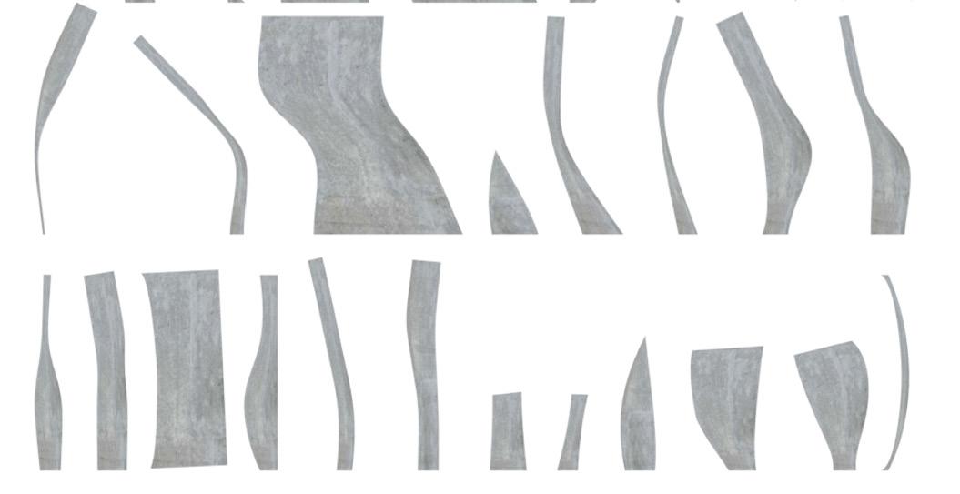
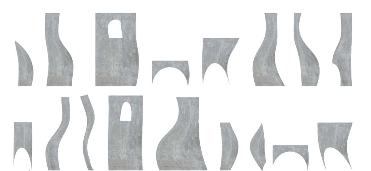
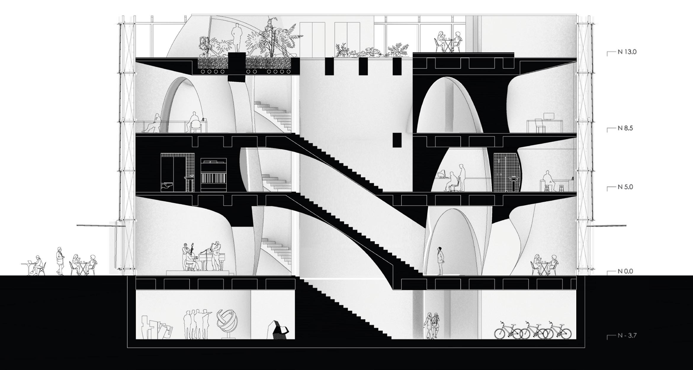
1. Exterior view, 2. Core walls layout, 3. Longitudinal section
The first floor connects the building and residents to the neighborhood. Above this the residence vs work duality takes place. Sectors are separated by a noise buffer formed by large structural walls containing service areas and offices.
11
4.
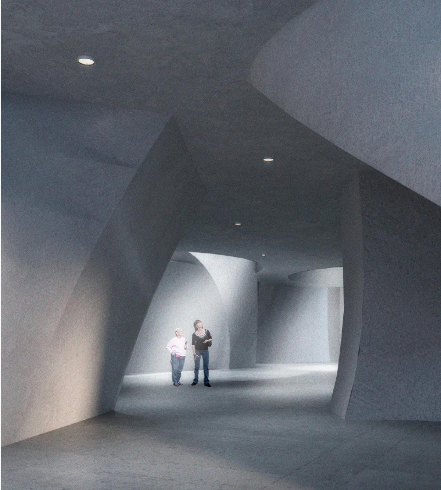
4. Interior view, 5. Sketches of the floor plan, 6. Cross section
5.
6.

12
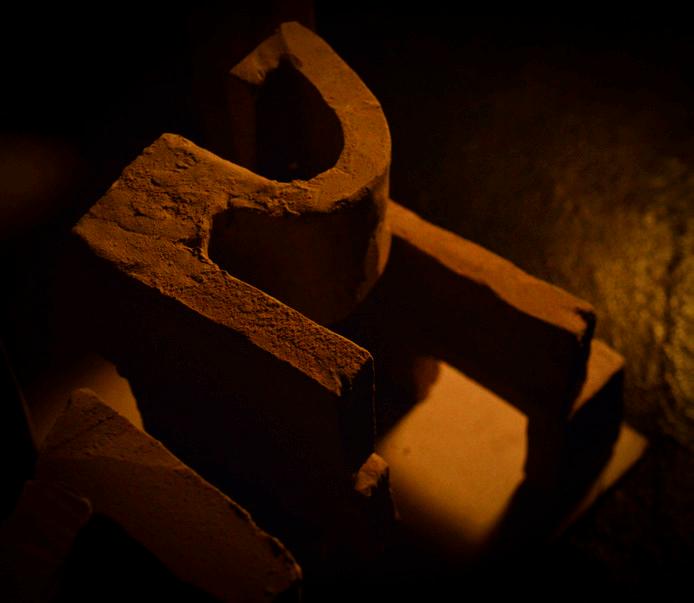
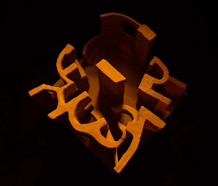
7.
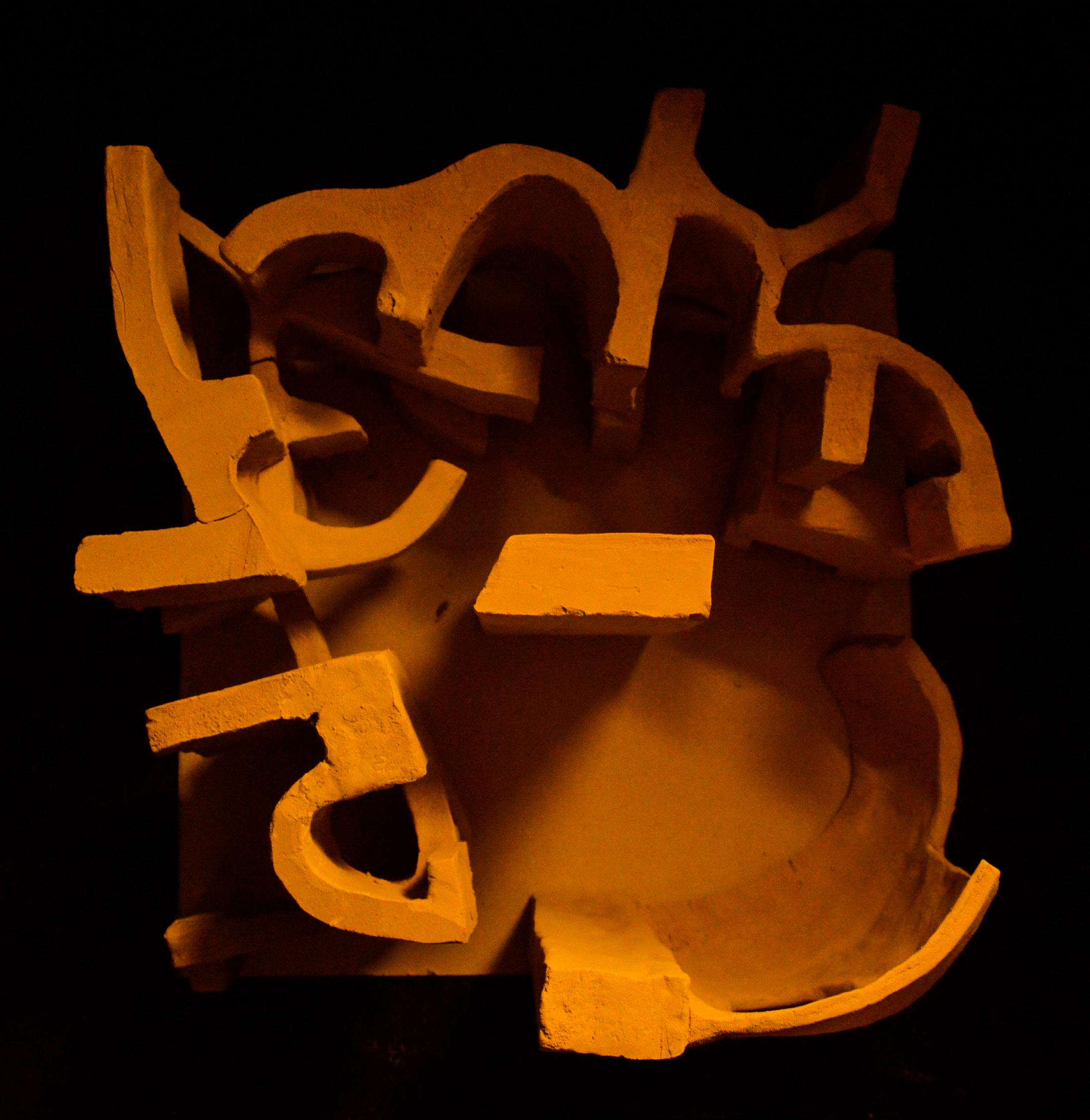
7. Clay model of
the curving structure
13
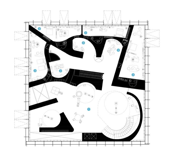
8.
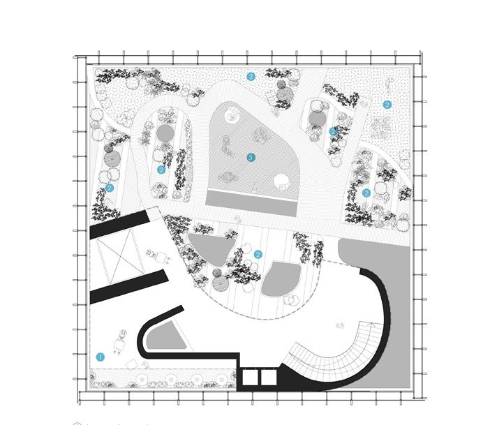
8. First floor, 9. Second floor, 10. Third floor, 11. Rooftop garden
10.
9.
11.


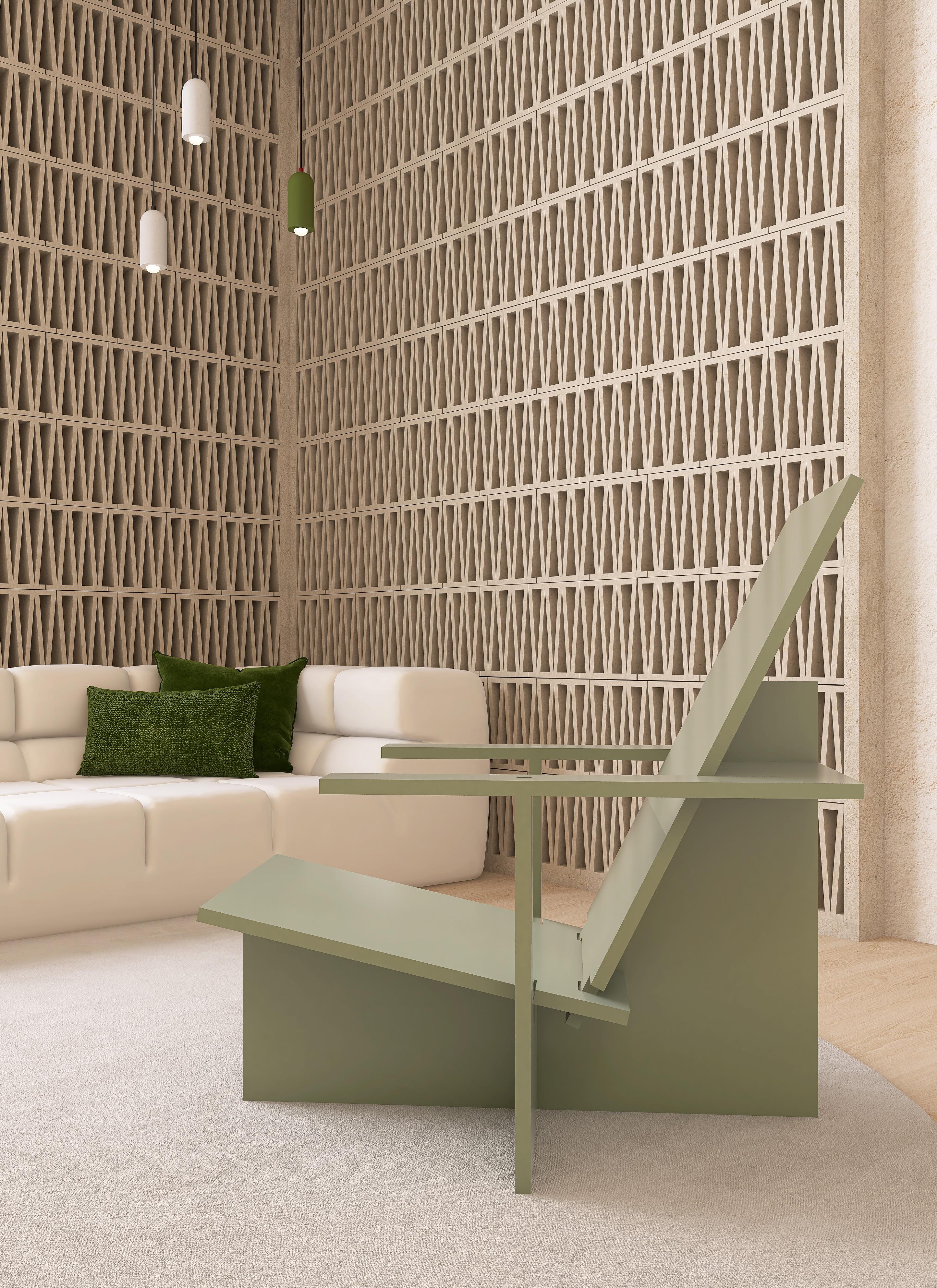
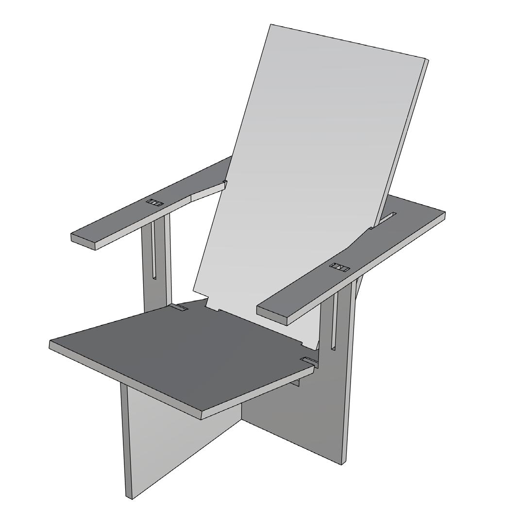
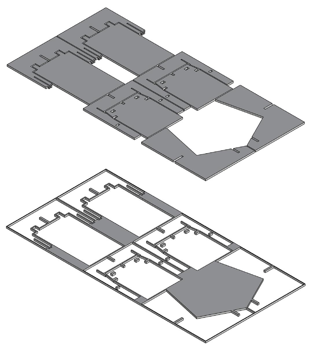
The chair’s design concept orginated from the idea of efficency by utilizing a single sheet of plywood with standard dimensions to make two chairs. Hence, the monosyllabus name SUT, in Spanish: “Sillas de Un Terciado”.
The SUT Chair uses only joints that interlock with no nails, glue or tools needed. Thanks to its complex and unique design the chair can be put together with three simple steps: Drawing, Cutting and Assembling.
The result is two elegant lounge chairs optimal for reading due to the seat inclination angles, armrests and seat height, which are similar to those of the famous Red Blue chair designed by the renowned architect Gerrit Rietveld.
14 1220 450 80 80 610 104° 13° 63° 865 450 718 2440 450 80 80 610
SUT CHAIR [PAT. PEND.]
1. 1.
a
of plywood, 2. Plans for Part A2 of the SUT Chair, 3. Steps for assembly and dissasembly 2. 3. 8' 4' SCALE: 1:8 1 D-1 SUT CHAIR PLAN SUT CHAIR JAVIER HABERLAND HABERLAND REVISIONS SHEET TITLE: SHEET NO. 05-09-2024 PAT PEND D-1 PLAN A1 A4 A3 A5 A2 A4 A3 A5 A2 A1 18 51/64 2 31/32 2 31/32 23 41/64 17 23/32 1 31/32 4 3/16 4 3/16 1 31/32 2 21/64 3/4 2 21/64 9 43/64 9 43/64 19 35/64 3/4 7 59/64 7 59/64 2 11/16 1 31/32 1 31/32 4 19/64 2 45/64 3/4 23 41/64 18 51/64 3/4 3/8 R5/32 39/64 39/64 49/64 49/64 R5/32 SCALE: 1:4 1 D-5 SUT CHAIR PART A2 SUT CHAIR JAVIER HABERLAND REVISIONS PAT PEND D-5 PART A2 SCALE: 1:1 2 D-5 SUT CHAIR PART A2 DETAIL
SUT chairs on
sheet
15 4.
4. SUT Chair rendering
16 5.
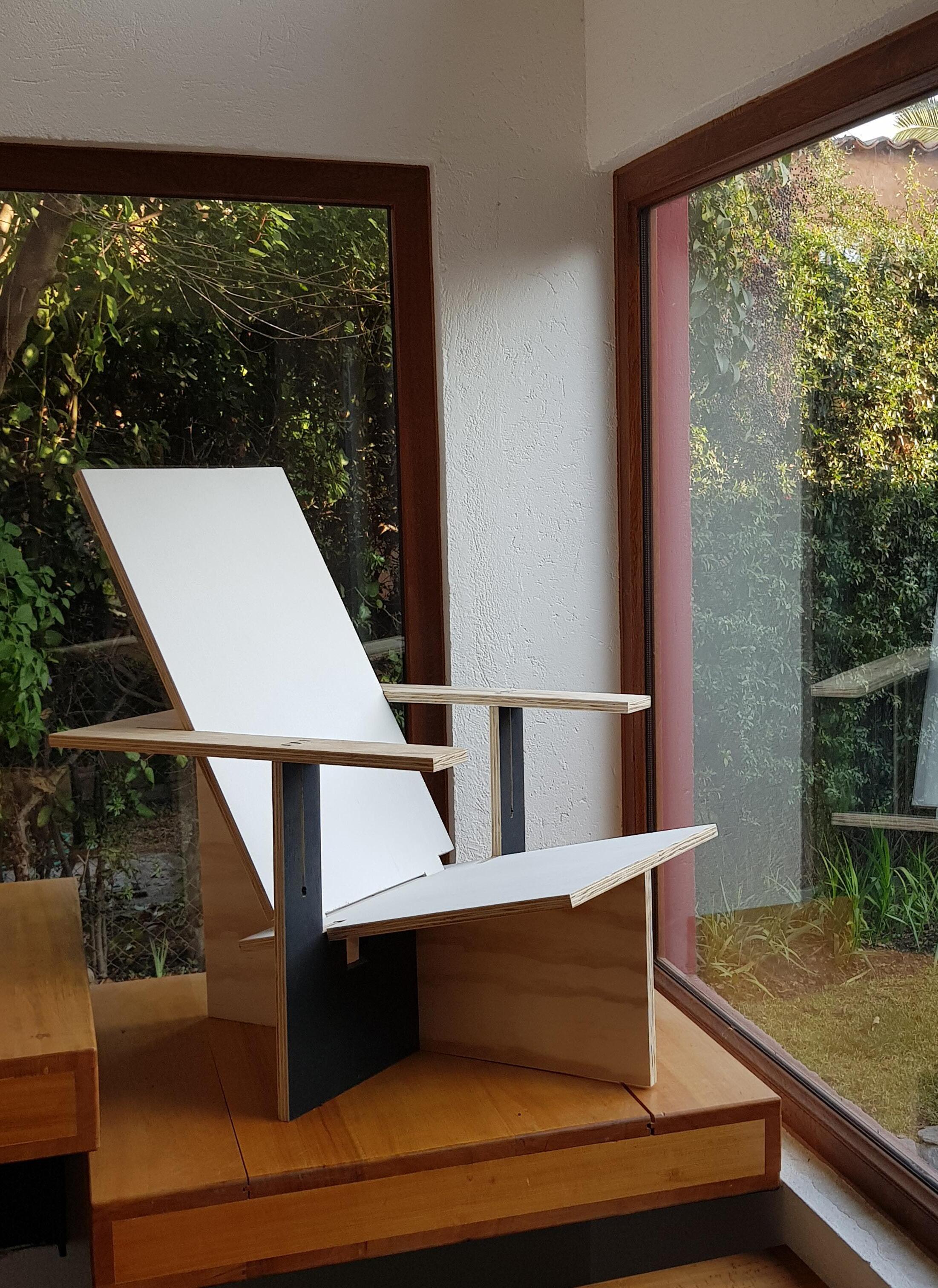
4. First SUT Chair [PAT. PEND.]
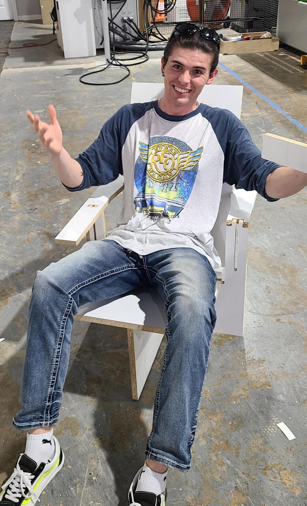
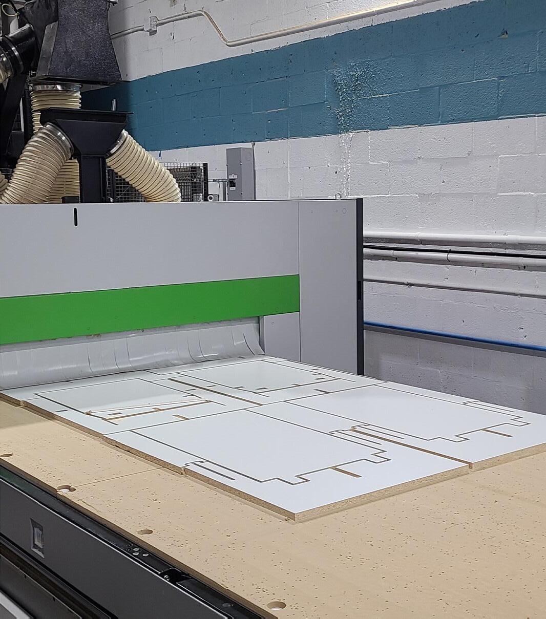
The first prototypes for the SUT chair are currently being produced in Miami using computer-aided design (CAD) and a CNC Router. With this technology it is possible to cut a variety of materials that come in a composite sheet format.
17
7.
7. 6.
6. CAD 3D modeling of the SUT Chair, 7. Myself on one of the first prototypes made of melamine, 8. CNC Router
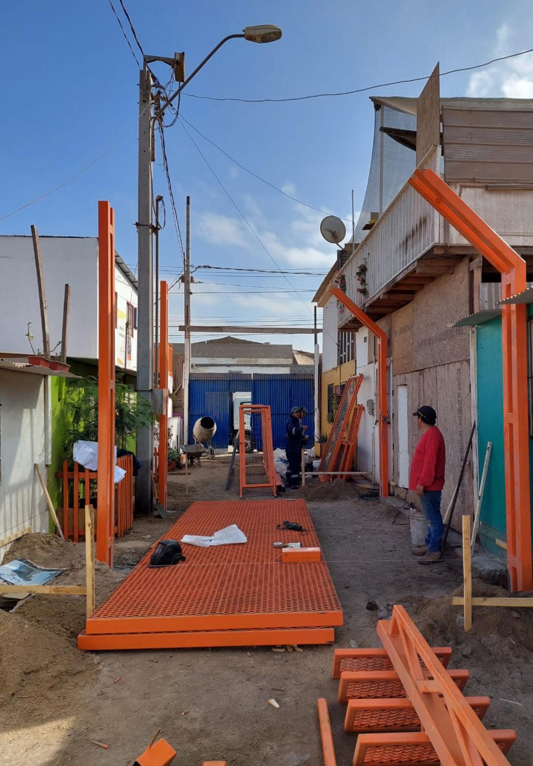
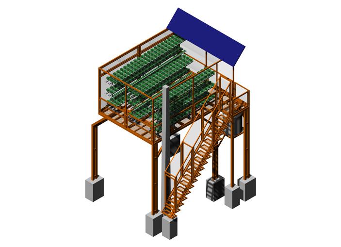
ARCHITECTURAL DESIGNER
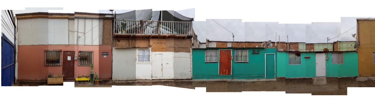
My proposal is part of a mega desalination project for Antofagasta and is a response to a call to generate productive activities in vulnerable sectors of the region. Its first prototype was built to intervene in transitional neighborhoods by means of elevated platforms that serve as small community centers for the production of vegetables in hydroponic gardens. In its design, special care was taken on the impact that its loadbearing structure would have on the passageway, the project was to allow the movement of water trucks, to be easily accessible to the community and to affect as little as possible the pre-existing dwellings.
18
RECREA
CRAMSA AND FOUNDATION
1. 2.
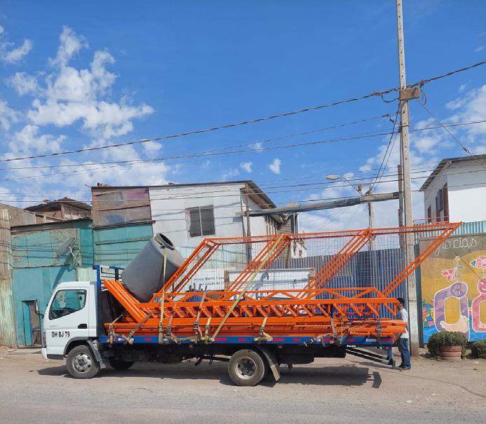
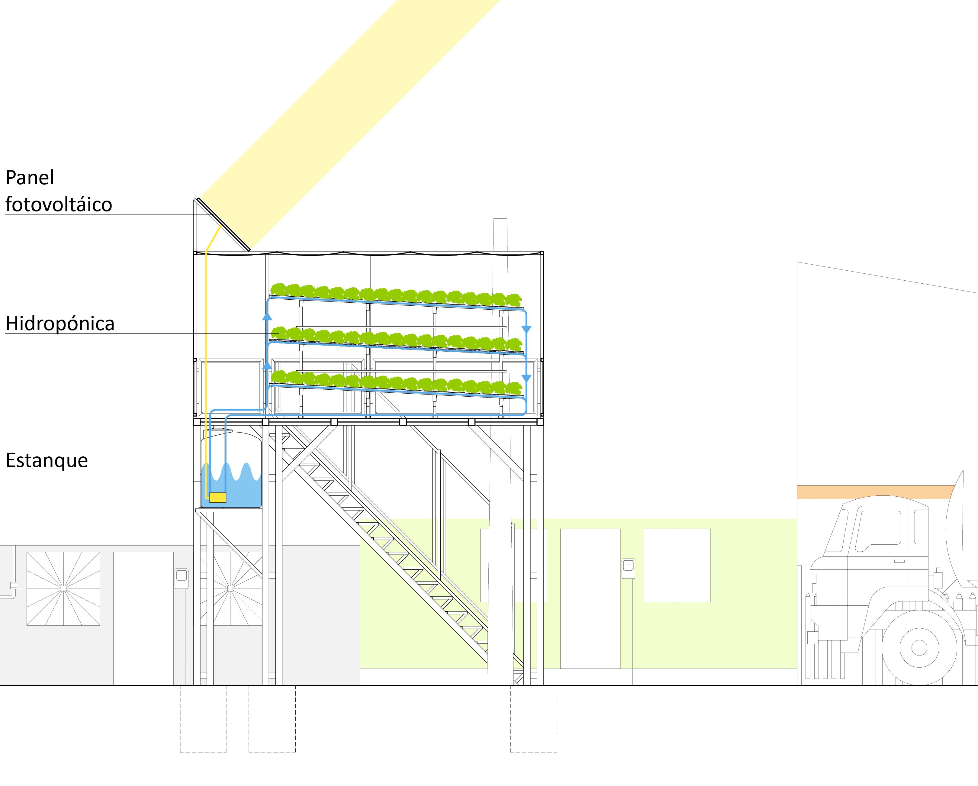
1. Assembly of prefabricated elements, 2. Arrival of elements at the site, 3. Systems section
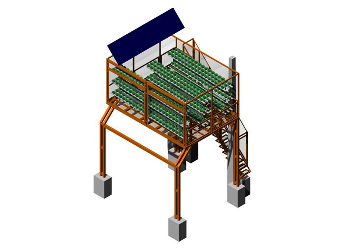
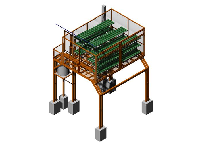
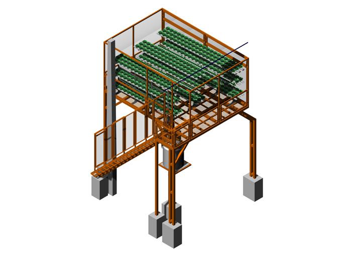
3. Photovoltaic panels
Hydroponics
Water tank
19
4. 5.
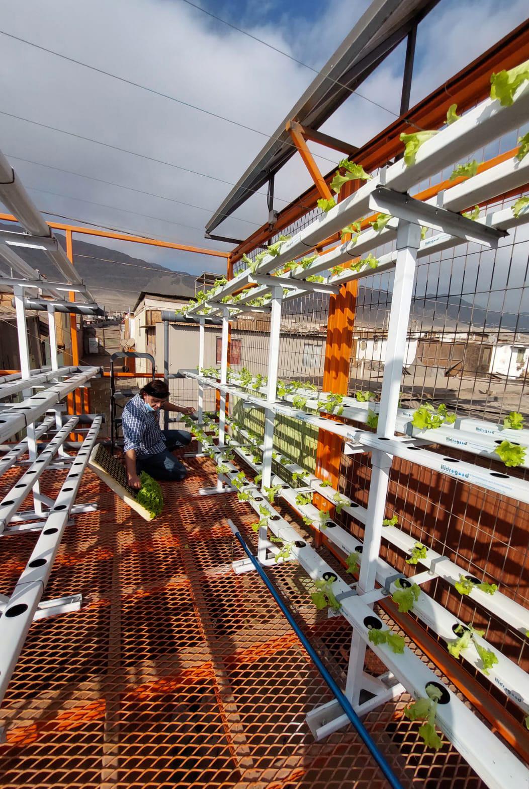
4. Hydroponic garden, 5. 3D model isometric views, 6. Neighborhood photomontage
6.
7. Plan and sections for the construction of La Chimba Hydroponics Project.
20
7. 2 1 3 4 5 6 7 ELEVACIÓN FRONTAL ESC 1:20 0 100 200 400 N +4.0 m Altura plataforma NTN+/-0.0
m
N +6.5
Altura cubierta
21 F E D C B A 2 1 3 4 5 6 7 F E D C B A ELEVACIÓN LATERAL ESC 1:20 0 100 200 400 446 173 173 100 86.5 86.5 86.5 86.5 100 515 103 103 103 103 103 44 70 52 88 52 88 52 479.5 381.5 108.5 456
name number email address
architect
Javier Haberland Canaves (754)-274-6754
javier.haberland@gmail.com Pompano Beach, FL 33062
(this portfolio was put together using Adobe InDesign)
JH

