23 minute read
3 Managing the Project
Project management is a key aspect of any construction project. Once a contract has been signed with the customer, the project schedule can commence for the construction of the PV system. Longer lead time system components such as modules, inverters, and combiner boxes can be ordered while drawings are being finalized and the permit package is being assembled for submittal. The construction foreman must be informed of the project plans and be given the opportunity to provide their input to the process to implement any necessary improvements to the construction process. A healthy feedback mechanism should be in place to make continual process improvements and learn from the mistakes of past projects. Failure to make process improvements when managing projects will lead to a loss of morale with the construction crew and ultimately result in high labor turnover rates.
In summary, planning a PV installation utilizes information gathered during a site survey, and includes the following considerations:
Advertisement
• Reviewing, completing and adapting the system design • Submitting applications for permits, utility interconnection and incentives • Defining the project schedule, manpower and equipment needs • Identifying and resolving construction activity conflicts such as power outages or alterations to the site • Coordinating other logistics with the customer such as site access, worker facilities, waste collection and storage areas
3.1 Secure Permits and Approvals
A complete permit package is critical to an expeditious permitting and approval process. When working with jurisdictions for the first time, it is always valuable to schedule a meeting with the building department and develop an understanding of the expectations of the jurisdiction on the contents of a permit package. Jurisdictions that are new to PV systems will require more time and effort in processing the paperwork for construction approval. While it is rarely a problem to provide too much information, the information must be relevant and well organized so the plan reviewer can perform their review as efficiently as possible.
The benefit of having a positive and helpful attitude when working with jurisdictional personnel is hard to understate. Most jurisdictional employees are overworked, underpaid, and underappreciated. Showing an appreciation for their role in the construction process can make big difference in how a permit package is received. Too often contractors get a bad attitude about having to work through the bureaucracy of local government. That attitude often comes across loud and clear to the jurisdictional employees causing them to lose any possible motivation they might have had to process the paperwork in a timely manner. For a plan checker with little or no PV experience, offering to be available for questions and clarifications can help move the process more quickly.
A high quality permit package is one of the most effective methods of establishing a good rapport with the local jurisdiction. The contents of a high quality permit package include:
• A title page with the project address, brief project description, list of project specifications, and a table of contents. • Completed forms that the local jurisdiction requires to process a permit. • A site plan that shows the location of major components on the property including array layout, location of access pathways for rooftop system for fire department review, setbacks to property lines for ground mounted systems, and location of the utility disconnect if required. • Detailed electrical diagram showing and specifying all major components used in the electrical portion of the PV system. This diagram must show the configuration of the
PV array, the location and ratings of overcurrent protection and disconnecting means, callout conduit and wire size, type, and ratings. The electrical diagrams should also include specifications and content for the required signs and labels. • Mounting structure information including manufacturer, model, installation documentation and details. • Specification sheets for all major electrical equipment including PV modules, inverters, combiner boxes, and any other unique components that are not common in conventional electrical installations.
Some jurisdictions may handle the entire approval process by submitting a single package of materials with multiple copies for distribution to several internal departments. Other jurisdictions may require separate submittals to be filed with the building department, planning and zoning department, fire department, and any other relevant department. Knowing and understanding how to navigate the approval process takes time and focus so that projects can work their way through the process as quickly as possible.
3.2 Preconstruction
The proper preparation for construction is as important as the actual construction process itself. Making sure all required material is on hand or procured to be available by the time it is needed on the site requires significant planning and project experience. All PV projects require a safety plan, and safety equipment must be on hand prior to construction. The safety equipment must be inspected to insure that it is in good repair and has no missing pieces. Any necessary equipment rentals need to be planned, budgeted, and deliveries scheduled. Often large amounts of materials may need to be staged and moved into position in preparation for construction, requiring special equipment. A number of software tools are available to assist construction managers in planning and allocating project resources.
3.3 Project Labor
Determining the amount and proper allocation of project labor is critical to a smooth and efficient construction project. In the pressure and busyness of project preparations, a commonly overlooked aspect of the construction process is good communication with the construction crew as to their roles and reasonable expectations. A key component of that process is training the crew for the specific job needs of the project. Even experienced project labor needs continuing education on aspects of the project that may slightly different than previous projects. Since materials, mounting systems, modules, and inverters are constantly changing in the dynamic PV world, some level of personnel training will be involved in each project, including site-specific safety hazards, at a minimum.
Assuming that a crew has all the knowledge and materials to carry out the project is an all too common mistake in a construction project. This requires checking with project labor to make sure they are comfortable with their responsibilities and making sure that they are comfortable expressing recommendations for process improvement. Managing the morale of project labor requires a good understanding of the personalities in the crew and good motivational skills so that laborers are recognized and appreciated for a job well done.
3.4 Adapting System Design
In the early stages of a construction project it is often necessary to make adjustments to the project plan to address discrepancies between the site and system design, and unforeseen project obstacles. This may require adaptations to the system design. It is rare for a project to go completely as planned. Even with the best preplanning, issues beyond the control of the project manager invariably arise that require flexibility, such as making material substitutions due to product availability.
3.5 Implement a Site Safety Plan
A safe PV system is installed according to applicable building codes and standards. PV installer safety includes considerations for a safe work area, safe use of tools and equipment, safe practices for personnel protection, and awareness of safety hazards and how to avoid them. The installation of PV systems involves a number of safety hazards, principally electrical and fall hazards.
Working safely with PV systems requires a fundamental understanding of electrical systems and the safety hazards involved, in addition to normal work site and construction hazards. The common sense aspects for jobsite safety can be summarized as follows:
• If the workplace is cluttered, the possibility of tripping over something is significantly increased. • If the workplace is a sloped roof with clutter, the possibility of falling off the roof is significantly increased. • If tools are left lying out on a roof, the chance of the tools falling off the roof and injuring someone below is increased. • If the workplace is a rooftop in bright sunshine, the chance of sunburn and heat exhaustion is increased, so workers should take appropriate precautions like using sunscreen, keeping well-hydrated and wearing light-colored clothing.
There are the usual subtle hazards, as well. These include nicks, cuts, and burns from sharp or hot components. Gloves should be used when handling anything that might be sharp, hot, rough, or that might splinter. Special insulating gloves are required for working with live voltages. There is always the possibility of dropping tools or materials on either oneself, someone else, or on sensitive equipment or materials. Dropping conductive tools across battery terminals is an especially dangerous hazard. When a PV system is being assembled, it presents the possibility of shock to personnel. Proper procedure during installation can reduce, and often eliminate hazards including electrical shock. Improperly installed systems may result in shock or fire hazards developing over time due to wiring or arcing faults.
3.5.1 OSHA Regulations
All individuals working on or contracting installation services for PV systems should be familiar with standards established by the Occupational Safety and Health Administration (OSHA), contained in Volume 29 of the U.S. Code of Federal Regulations (29 CFR). OSHA regulations are applicable in all U.S. states and territories and enforced by federal or local authorities. States with OSHA-approved programs must set standards at least as effective as federal standards. These standards apply to private employers and general industry, for construction, maritime, agricultural and other occupations. The broad scope of OSHA regulations includes health standards, electrical safety, fall protection systems, stairways and ladders, hand and power tools, cranes and lifts, excavations, scaffolding, and other potential hazards likely to be encountered in constructing PV systems.
OSHA regulations require that employers provide a safe and healthful workplace free of hazards, and follow the applicable OSHA standards. Employers must provide safety training addressing all probable hazards on a construction site, and employers of 11 or more employees must maintain records of occupational injuries and illnesses. All em-
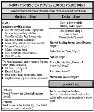
Figure 82. The OSHA 10-Hour Construction Industry Training Program is strongly recommended for PV installers.
ployers must display the OSHA poster, and report to OSHA within 8 hours any accident that results in a fatality or hospitalization of three or more employees. Workers are responsible for following the employer’s safety and health rules and wear or use all required safety gear and equipment, reporting hazardous conditions to OSHA if employers do not fix them, and cooperating with OSHA inspectors. Large construction projects often require workers to complete 10 hour training on OSHA regulations and have a valid course completion card for insurance purposes.
Safety and Health Regulations for Construction (29 CFR Part 1926) applies to general construction, including several subparts applicable to the installation of PV systems:
Subpart C - General Safety and Health Provisions Subpart D - Occupational Health and Environmental Controls 2011 Jim Dunlop Solar Subpart E - Personal Protective and Life Saving Equipment Subpart I - Tools, Hand and Power Subpart K - Electrical Subpart M - Fall Protection Subpart X - Stairways and Ladders
OSHA Figure 83. The OSHA 10-Hour Construction Industry Training Program is strongly recommended and may be required for PV installers.
OSHA 10
The OSHA 10-Hour Construction Industry Training Program is intended to provide entry-level construction workers with a general awareness on recognizing and preventing hazards on a construction site. Many projects require all construction workers on a jobsite to have a current OSHA 10 training. Workers must also receive additional training on hazards specific to their job. See Fig. 83.
Cells, Modules and Arrays: 5 -85
NREL/Rob Williamson
NREL/Rob Williamson
Figure 84. Skylights must be protected from fall hazards by barriers or covers. Alameda County JATC/Mel Switzer
2011 Jim Dunlop SolarFigure 84. Fall protection is a primary safety concern for PV installers.
2011 Jim Dunlop Solar
3.5.2 Fall Protection
Falls are the leading cause of deaths in the construction industry. Because most PV systems involve climbing ladders, or working on rooftops, it is essential that PV installers are familiar with OSHA fall protection regulations. Most fatalities occur when employees fall from open-sided floors and through floor openings. Consequently, OSHA requires that fall protection be used for walkways and ramps, holes and excavations,
Alameda County JATC/Mel Cells, Modules and Arrays: 5 -86
roofs, wall openings or skylights Switzer A PV installer fell to his death where an employee or worker can through this skylight. fall 6 feet or more. Employers must Cells, Modules and Arrays: 5 -86 provide training to employees on how to recognize and minimize fall hazards, and the use of fall protection systems and devices. See Figs. 84, 85 & 86. Fall protection options include Personal Fall Arrest Systems (PFAS), guardrails and safety nets, and must be in place before work commences. See Figs. 87 & 88. Train-
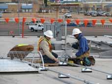
Figure 85. Warning lines designate safe areas in which work may take place without the use of PFAS.
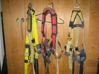
National Electric Figure 86. A personal fall arrest system (PFAS) consists of an anchorage and connectors, a body California Dept. of Public Health harness, and a lanyard/deceleration device.
Figure 85. Skylights must be protected from fall hazards by barriers or covers.2011 Jim Dunlop Solar
Cells, Modules and Arrays: 5 -87
Warning Line
National Electric Body Harnesses
Jim Dunlop Lanyard, Lifeline and Roof Anchors

Jim Dunlop
Figure 86. Warning lines designate safe areas in which work may take place without the use of PFAS. Figure 87. A personal fall arrest system (PFAS) consists of an anchorage and connectors, a body harness, and a lanyard/deceleration device.
2011 Jim Dunlop Solar Cells, Modules and Arrays: 5 -89
Cells, Modules and Arrays: 5 -88
Removable/Reusable Roof Anchors
2011 Jim Dunlop Solar
Concrete Dee-ring Anchor
Permanent Roof Anchor with Cap
Guardian Fall Protection
Figure 88. Safety line anchorages must be independent of any platform anchorage and capable of supporting at least 5,000 pounds per worker.
Figure 89. A stairway or ladder is required at points of access to a construction site where there is a break in elevation of 19 inches or more.
Cells, Modules and Arrays: 5 -90
ing is required on how to properly use and maintain PFAS, including the anchorages, lifelines and body harnesses. Guardrails used to protect open-sided floors and platforms must have top rails between 39 and 45 in tall, a mid-rail, and toe boards at least 3-1/2 in high. Safety nets must be deployed no further than 30 ft below where work is performed, preferably closer. In certain applications, the use of designated safety monitors and warning lines may meet the requirements, but is the least desirable of all fall protection systems. In any case, it is best practice to perform work at ground level if possible, such as pre-assembly of PV panels and arrays.
Figure 88. A stairway or ladder is required at points of access to a construction site where there is a break in elevation of 19 inches or more.
3.5.3 Stairways and Ladders
OSHA requires that a stairway or ladder be used at points of access where there is an elevation break of 19 in or more on a jobsite. See Fig. 89. Stairways with four or more risers, or higher than 30 in, must be equipped with at least one handrail, capable of withstanding a force of 200 pounds. See Fig. 90. Stairways with four or more OSHA risers or more than 30 in high must have 2011 Jim Dunlop Solara stair rail along each unprotected side or Cells, Modules and Arrays: 5 -91 edge. Stairs must be installed between 30 and 50 degrees, must have uniform riser height and tread depth, with less than a 1/4-in variation. Stairways landings must be at least 30 in deep and 22 in wide at every 12 ft or less of vertical rise. Unprotected sides of landings must have standard 42 inch guardrail systems. Where doors or gates open directly on a stairway, a platform must be used that extends at least 20 Figure 90. Stairrails and handrails must be able to withstand 200 pound force. in beyond the swing of the door.
Figure 89. Stairrails and handrails must be able to withstand 200 pound force. OSHA
2011 Jim Dunlop Solar Cells, Modules and Arrays: 5 -92
Ladders must be kept in a safe working condition. Keep the area around the top and bottom of a ladder clear, and ensure rungs, cleats, and steps are level and uniformly spaced 10 in to 14 in apart. Use ladders only for their designed purpose. Never tie ladders together to make longer sections, or load ladders beyond the maximum load for which they are rated. A competent person must inspect ladders for visible defects, like broken or missing rungs, and if a defective ladder is found, immediately mark it defective or tag it “Do Not Use”, and withdraw defective ladders from service until repaired.
Ladders should be used on stable and level surfaces, and secured to prevent accidental movement due to workplace activity. Do not use ladders on slippery surfaces unless secured or provided with slip-resistant feet. Ladders, particularly wooden ones, should never be painted which can conceal defects. A double-cleated ladder (with center rail), or two or more ladders are required when ladders are the only way to enter or exit a working area with 25 or more employees, or when a ladder will serve simultaneous two-way traffic.
Non-self-supporting ladders (those that lean against a wall or other support) must be positioned at an angle where the horizontal distance from the top support to the foot of the ladder is 1/4 the working length of the ladder (the distance along the ladder between the foot and the top support). See Fig. 91. When using a portable ladder for access to an upper landing surface, the side rails must extend at least 3 ft above the upper landing surface. For step ladders, the top and top step should never be used as a step, and never use crossbracing on the rear of a stepladder for climbing — unless the ladder is designed for that purpose. Tall fixed ladders 24 ft or longer must be equipped with either: a ladder safety device; self-retracting lifelines with rest platforms every 150 ft or less; or cage or well, and multiple ladder sections, each section not exceeding 50 ft.
Ladder Angle
Min 3 ft Tie-off points
If using ladders where the employee or the ladder could contact exposed energized electrical equipment, such as transformers or overhead services, ladders must have nonconductive side rails such as wood or fiberglass. Face the ladder when going up or down, and use at least one hand to grab the ladder when going up or down. Do not carry any object or load that could cause you to lose balance while climbing ladders.
16 ft
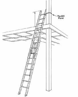
4 ft
OSHA Figure 91. Ladders must be used with the proper angle and secured at the appropriate height.
Cells, Modules and Arrays: 5 -4
3.5.4 Hand and Power Tools
Power tools are extremely hazardous when used or maintained improperly. Workers using hand and power tools may be exposed to a number of hazards, including objects that fall, fly, are abrasive, or splash; harmful dusts, fumes, mists, vapors, and gases; and frayed or damaged electrical cords, hazardous connections and improper grounding. Eye protection is usually always required.
All hand and power tools and similar equipment, whether furnished by the employer or the employee, shall be maintained in a safe condition. All power tools must be fitted with factory guards and safety switches, and hand-held power tools must be equipped with a constant pressure switch or on-off switch. Hazards are usually caused by misuse and improper maintenance.
Additional guidelines and precautions for using power tools include the following:
• Follow manufacturers’ instructions • Use the proper personal protective equipment (PPE) • Disconnect tools when not in use, for cleaning, and when changing accessories • Secure work with clamps or a vise, freeing both hands to operate the tool • Inspect tools regularly before use and maintain in sharp, clean condition • Do not wear loose clothing and jewelry that can get caught in moving parts • Do not use electric cords to carry, hoist or lower tools • Keep cords and hoses away from heat, oil, and sharp edges • Remove damaged electric tools & tag them: “Do Not Use.”
3.5.5 Personal Protective Equipment (PPE)
Personal protective equipment (PPE) includes protective clothing, gloves, footwear, helmets, goggles, respirators, aprons or other garments designed to protect workers from injury to the body by impacts, electrical hazards, heat and chemicals, and other job-related safety hazards. PPE is the last measure of control when worker exposure to the safety hazards cannot be totally eliminated by feasible work practices or engineering controls.
Responsibilities of the employer include assessing the workplace for hazards, providing PPE, determining when to use it, and providing training for affected employees. Employee responsibilities include using PPE in accordance with training received and other instructions, and inspecting daily and maintaining the PPE in a clean and reliable condition.
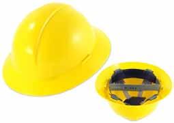
The employer shall ensure that each affected employee wears a protective helmet when working in areas where there is a potential for injury to the head from falling objects, or exposure to electrical hazards. See Fig. 92. Type I hard hats provide protection from blows only to the top of the head. Type II hard hats have a full brim and provide protection from blows to the top or sides of the head. Class G (General) hardhats are intended to reduce the danger of contact exposure to low voltage conductors and are proof tested to 2,200 volts. Class E (Electrical) hardhats are intended to reduce the danger of exposure to high voltage conductors and are proof tested to 20,000 volts. Class C (Conductive)
Type II, Class E Hard Hat
Lab Safety Supply
Figure 92. Hard hats protect the head from blows and energized electrical conductors.
Vented and Indirect-Vent Goggles

Impact Splash-Resistant Goggles
Lab Safety Supply Safety Glasses
Face Shield
Figure 93. Types of eye and face protection include safety glasses, goggles and face shields.2011 Jim Dunlop Solar Cells, Modules and Arrays: 5 -95
Cells, Modules and Arrays: 5 -94
hardhats provide no electrical insulation and not intended to provide protection against contact with electrical conductors.
Eye protection must be provided to protect against hazards such as dust and other flying particles, corrosive gases, vapors, and liquids, and welding operations. See Fig. 93. The selection of eye protection is based on protection from a specific hazard, its comfort, and must not restrict vision or movement, or interfere with other PPE. Types of eye and face protection include:
• Safety glasses: Single or double lens; close and comfortable fit important.
Prescription lenses available. • Goggles: Offer the most complete protection from impacts, chemicals and vapors by sealing around the eye area. Vented types allow air flow and reduce the chance for fogging, but protect from impacts only. Non-vented and indirect-vent types protect from impacts as well as splash, vapors or particles; use lens coatings for better anti-fog performance. Many types fit over prescription eyeglasses. • Face shields: A supplementary, secondary protective device to protect a worker’s face from certain chemical and welding radiation hazards. Must use with safety glasses for impact protection. Special lenses and shade number required for specific welding operations.
Hearing protection must be used whenever an employee’s noise exposure exceeds an 8-hour time-weighted average (TWA) sound level of 90 dBA. Noise levels above 115 dBA require control measures for any duration. OSHA also recognizes an 85 dBA TWA as an action level to monitor noise levels. Noise levels likely exceed 85dBA if one has to raise their voice to converse with another person 3 feet away. Hearing protection options include earmuffs that fit over the ear and seal against the side of the head, disposable and reusable earplugs inserted directly into the ear canal, or hearing bands. See Fig 94. All approved hearing protectors have an assigned Noise Reduction Rating (NRR) in decibels.
Earmuffs
Fit over the ear and seal against the side of the head.
Earplugs
Inserted directly into the ear canal.
All approved hearing protectors
have an assigned Noise
Reduction Rating (NRR) in decibels.
Reduces decibel exposure.
2011 Jim Dunlop Solar
Reusable Earplugs Disposable Foam Plugs
Hearing Bands
Lab Safety Supply Ear Muffs
Cells, Modules and Arrays: 5 -96
Figure 94. Hearing protection should be used whenever using machinery or power tools with noise levels exceeding 85 dB.
When employees are exposed to harmful atmospheres, dust or vapors, the employer shall provide respirators which are applicable and suitable for the purpose intended. Although not generally required, certain construction tasks related to a PV installation may require respiratory protection, such as working in insulated attics.
Foot protection must be used when any of the following conditions are present: heavy objects such as barrels or tools that might roll onto or fall on employees’ feet; sharp objects such as nails or spikes that might pierce ordinary shoes; molten metal that might splash on feet; or working on hot, wet or slippery surfaces. Safety shoes have impact-resistant toes and heat-resistant soles, and may be electrically conductive for use in explosive atmospheres, or nonconductive to protect from electrical hazards.
All types of protective footwear must include an identification label listing the applicable standard, manufacturer, and specifications. All protective footwear must provide impact and compression resistance. Impact resistance (I) is rated for 75, 50 or 30 foot-pounds. Compression resistance (C) is rated for 75, 50 or 30 which correlates to 2500, 1750 or 1000 pounds of compression resistance.
Protective footwear may also meet the following specifications as labeled:
• Metatarsal resistance (Mt) is rated for 75, 50 or 30 foot-pounds. • Conductive (Cd) footwear is used to dissipate static electricity in explosive environments. • Electrical hazard (EH) footwear has non-conductive soles and provides secondary protection from live electrical equipment. • Puncture resistant (PR) footwear provides integral protection from sharp objects penetrating the sole. • Static dissipative (SD) footwear reduces the accumulation of excess static electricity for electronics environments. • Chain saw cut resistant (CS) footwear. • Dielectric insulation (DI) footwear is designed to provide additional insulation for contact with energized electrical conductors.
Employers shall select and require employees to use appropriate hand protection when employees’ hands are exposed to hazards such as harmful substances; severe cuts or lacerations; severe abrasions; punctures; chemical burns; thermal burns; and temperature extremes. See Fig. 95. Employers shall base the selection of the appropriate hand protection on an evaluation of the performance characteristics of the hand protection relative to the tasks to be performed, conditions present, duration of use, and the hazards and potential hazards identified.
Types of gloves vary widely in materials and application, including:
• Durable gloves made of mesh, leather or high-performance materials like
Kevlar® to protect from cuts, burns and heat. • Chemical-resistant rubber gloves to protect from burns and irritation • Electrical insulating gloves for exposure to live voltages
Correct glove size and fit is important for comfort and dexterity. Glove size is determined by diameter of the hand at its widest point. Common men’s sizes are: Small: 7½-8”, Medium: 8½-9”, Large: 9½-10”, and Extra Large: 10 ½-11”.
Figure 94. Gloves are rated for six levels of abrasion, cut and puncture resistance tested to ANSI/ASTM standards.
Level 2 Cut-Resistant Kevlar® Gloves Level 5 Cut-Resistant Leather Gloves
Chemical-Resistant Gloves Class 0, Low Voltage Gloves
Lab Safety Supply
2011 Jim Dunlop Solar Cells, Modules and Arrays: 5 -97Figure 95. Gloves are rated for six levels of abrasion, cut and puncture resistance tested to ANSI/ASTM standards.


