5 minute read
4 Description

from Jva Z13

Description
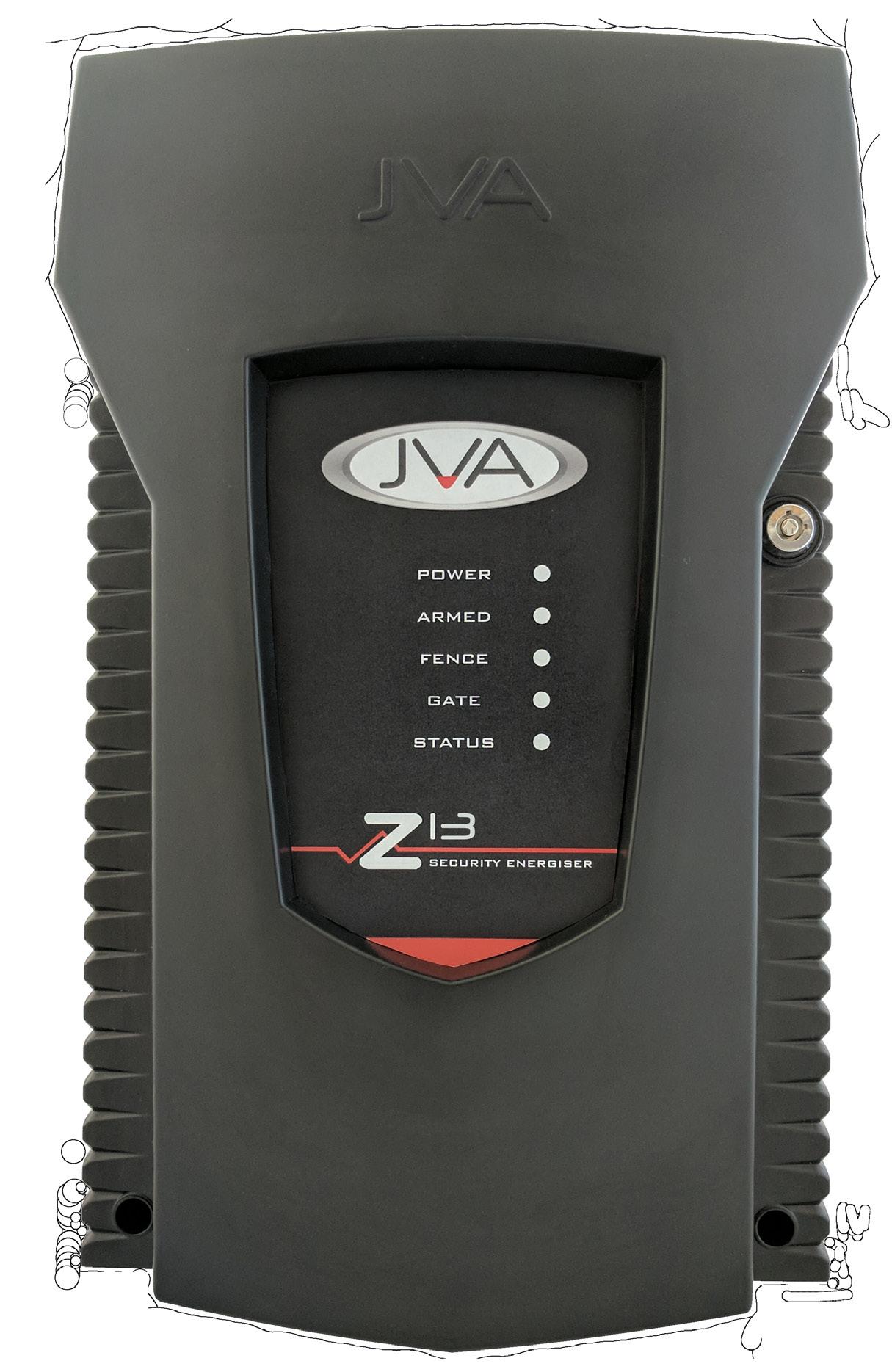
5.1 JVA Z13 - EXTERIOR
Advertisement
Status Light Description POWER On whenever the unit has power ARMED On when the unit is armed (pulsing), will flash when in Low Power mode FENCE Green when voltage on and OK, Red when there is a fence alarm GATE On when there is a gate alarm STATUS/FAULT The number of times the status/fault light flashes indicates any faults on the energizer. See the table in section “8.4 Status Codes” on page 35
5.3 INPUTS AND OUTPUTS
See “8 Technical Information” on page 33.
5.4 Z-SERIES MODELS
Z13 Single zone, conventional 1.5 Joule. Z13 Single zone, conventional 2.8 Joule. Z14 Single zone, conventional or Bi-Polar 5 Joule. Z14R Z14 with relays and IR Tamper circuit, 4 Joule. Z14E Z14 for high value animals. When the Z13E detects a ground short it switches to low power mode until the short is removed. If an animal is caught in the fence, causing the short, it will be in less distress than with a conventional security energizer. Z18 Single zone, conventional or Bi-Polar 8 Joule, contains relays and IR Tamper circuit. Z28 Dual zone, conventional 8 Joule (4 Joules per zone). ZM1 Single zone start of fence monitor with Distant Fault Detection ™ ZM20 Twenty sector loop monitor. ZLM4 Four zone low voltage electric fence monitor.
Description
Description
A Z-Series keypad allows for easy remote control of your JVA energizer. Arming and disarming, responding to alarms or just checking the fence voltage, the keypad makes this easy through a simple menu system or key sequences (shortcuts). Your security is protected by a user PIN. A keypad is required to change the programmable options, see “9 Installation Programming Options” on page 37.
5.5 INTERNAL BEEPER/KEYPAD BEEPER
Depending on the chime setting, the internal beeper and keypad beeper will sound when there is a fence alarm, a gate alarm, a door chime or a general alarm. Should the battery voltage run low, the keypad will beep 4 times before the energizer automatically enters Low Power mode to preserve the battery. 5.6 PROGRAMMABLE OPTIONS
The Z13 has many programmable options. To alter these options, a Z-Series keypad must be used. The options are explained in “9.5 Programming Options in Detail” on page 38. Each parameter has a factory set default.
5.7 ARM INPUT AND KEY SWITCH
The JVA Z-Series energizer can be armed (to energise the fence) by closing a contact wired into the arm input. On some models a key switch is fitted to the right-hand side of the case for this purpose. An external switch device, for example a remote receiver or access control keypad, can also be wired into the energizer to arm and disarm the unit.
5.8 GATE INPUT
An input can be configured for a Gate Function and wired to a gate switch to trigger an alarm when a gate is opened. Alternatively, it may be programmed to many other functions. For more information see “9.5.20 Input Function and Trigger” on page 50.
5.9 LOW POWER MODE
Z13 energizers can be switched into Low Power mode. Low Power mode may be used in situations where the fence is not required to be a deterrent but is still required to actively detect intrusion. In Low Power mode the fence live wires operate at a much lower voltage, typically 500V peak.
The Z-Series Energizer can be armed in Agricultural Mode to provide a way test the fence without triggering any of the alarms. This mode should only be used to confirm that a new installation is operating correctly. The Energizer will remain in this mode until the Energizer is Disarmed. The Fence Alarm LED will flash to indicate the return voltage is below the threshold, however it will not trigger the alarm.
5.11 GROUP SIMULTANEOUS PULSE FEATURE
In some installations it may be preferable to provide the ability to link multiple units into a group. When linked, the individual Z-Series devices become a group. As many as fifteen energizers can be grouped. Individual units in a group have simultaneous high voltage output pulses and act as if they are one energizer with multiple outputs. This is designed so that no possible combination of individual outputs can be dangerous. For more information see “14 Appendix A: Group Simultaneous Pulse Feature” on page 71 5.12 REMOTE CONTROL UNIT (OPTIONAL)
The Remote Control Unit provides the Z13 with the ability to arm or disarm the energizer via a compact key chain fob remote control. If using the remote control the siren can be used to acknowledge arming with 1 beep and disarm with 2 beeps, see programming option “9.5.11 Chime Mode (Option 14)” on page 43. The remote controls have a range of up to 100 metres. They come fitted with a LR27A 12V battery that will provide up to 2 years service. 5.13 CABLING
High voltage cabling (fence feed and returns) should be run using suitably rated cable. Double insulated electric fence “underground” cable is suitable. High voltage cables must never be run within the same conduit as low voltage cables. A minimum distance of 30mm should be kept between high voltage and low voltages cables. To maintain the IPx4 rating of the enclosure and to ensure moisture does not enter the enclosure via the cable entry area a silicon sealant (neutral cure) must be used to seal all the cable passages.
Description
Description
Although the Z13 contains internal lightning protection elements, external lightning protection elements such as additional external lightning protection kits are recommended to further reduce lightning damage and thus reduce repair costs. They are available from your local dealer.
5.15 EARTH LOOP MONITORING
The Z13 has two fence earth terminals. If the earth monitoring facility is not required, the Earth Out and Earth Return terminals must be joined with a wire bridge. Directions on how to wire for earth loop monitoring are in Section “6.3 Example of Fence (High Voltage) Wiring Diagrams” on page 29.
5.16 NOISE AND INTERFERENCE
The Z13 contains a microprocessor. Extreme electrical noise can upset microprocessors. The most likely cause of such noise is the high voltage output from the unit itself. In the event of erratic behaviour, check that the high voltage wiring is firmly connected to the terminals and that no sparking is seen. The Z13 is designed to self-recover from interference. Powering off (both AC and battery) should not be necessary. 5.17 PC CONTROL
A standard Windows PC may be used to control and monitor a group of ZSeries devices. Ask your JVA distributor for a demonstration of Perimeter Patrol™ software. Z-Series devices can be connected to a PC using either a serial data adaptor, such as the PAE223 or TCP/IP using a PAE212.

