7 minute read
Surface during Turning, Martin Barath, Jan Zitnansky, Hristo Beloev

from Agricultural, Forest and Transport Machinery and Technologies (ISSN: 2367– 5888) vol VII, 2020
by kangalov

Influence of Cutting Speed to Vibrations and Roughness of Machined Surface during Turning
Martin Barath, Jan Zitnansky, Hristo Beloev
Advertisement
Abstract: This paper deals with influence of cutting parameters to vibration during turning of steel on metal lathe. We observed the effect of changing cutting speed to machine vibration and the quality of the machined surface. Cutting parameters was changed in five steps. We used piezoelectric accelerometer MMF KS78.100 to sense vibrations, data acquisition unit Adlink USB 2405 was used for recording and processing signals from accelerometers. Recorded signals were transformed by Fast Fourier Transform from time domain to frequency domain. Software Visual Signal DAQ Express was used to perform this transformation. Keywords: vibration, turning, cutting parameters, roughness, acceleration
INTRODUCTION
The theory of vibrations and chatter has been known for long time. However, new transducers and their improvements have occurred, as well as new possibilities in data acquisition and computing equipment, which make methodologies and approaches to avoid vibrations more reliable and suitable for industrial application (Kuljanić et al., 2008). Vibrations have negative effect to whole process of chip machining. Badiola et al. (2019) determine these problems:
Chatter vibration is a common problem in almost all cutting operations which limits productivity of machining processes. Chatter vibrations cause poor workpiece surface finishing, premature tool wear, and breakage of cutting tools. Furthermore, due to this phenomenon, the machine tool life, reliability, and safety of the machining operation are affected negatively. Chatter vibrations have been researched for more than a century and it is still a major obstacle in achieving automation for most of the machining processes.
MATERIALS AND METHODS
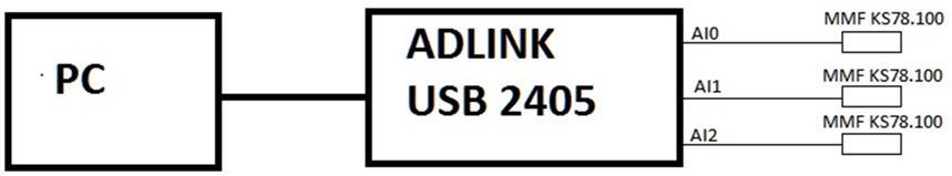
For the purposes of our experiments we used measuring device which consist from accelerometers MMF KS78.100 connected to signal acquisition module Adlink USB 2405 and PC with software Visual Signal DAQ Express. Block diagram of this device is shown in Fig.1.
Fig. 1 Block diagram of measuring device
Adlink USB 2405
The USB-2405 shown in Fig.2 is a 24-bit high-performance dynamic signal acquisition USB module equipped with 4 analog input channels providing simultaneous-sampling at up to 128 kS/s per channel. The USB-2405 also features software selectable AC or DC coupling input configuration and built-in high precision 2 mA excitation current to measure integrated electronic piezoelectric (IEPE) sensors such as accelerometers and microphones. The USB2405 is USB bus powered and equipped with BNC connectors and removable spring terminals for easy device connectivity (Adlink, 2020).

Fig. 2 Adlink USB 2405 signal acquisition module (Adlink 2020)
Accelerometer
Piezoelectric accelerometers use piezoelectric material in their design to create a charge proportional to the mechanical stresses caused by acceleration. Piezo crystal charge is measured either directly by external electronics with a high input impedance value, or more often the internal sensor electronics converting the charge to a low impedance voltage output. The disadvantage of these accelerometers is that they cannot be used to measure frequencies below 0.1 Hz. One side of the piezoelectric material is attached to a solid sensor base. The part named as seismic mass is attached to the piezo-sensor. If the accelerometer is exposed to acceleration (vibration, shock), the generated force F, which acts on the piezoelectric element, will generate a charge, respectively voltage at the sensor output (Hudák, 2009). We used two accelerometers MMF Ks78.100 shown in Fig.3.
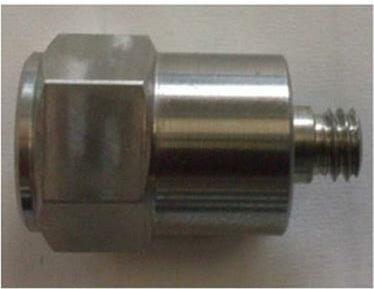
Fig. 3 Accelerometer MMF KS 78.100
Visual Signal DAQ Express software
Visual Signal is a signal processing software developed to provide time-frequency analysis solutions in an intuitive way. The design eliminates the complicated ways of writing a program to produce visual process control components, and instead provides a variety of visual process control components to be utilized. This gives users the ability to create a presentation of their own ideas for analysis without the limitation of needing to be able to code it (http://www.ancad.com/VisualSignal/overview.html).
Mitutoyo Surftest 301
Mitutoyo Surftest 301 is a portable measuring instrument that allows you easily and accurately measure surface roughness. It performs roughness analyses conform to various international standards (EN ISO, VDA, ANSI, JIS) and customized settings. Display range: Ra, Rq: 0.01 µm - 100 µm; Ry, Rz, Rt, Rv, R3z, Rk, Rpk, Rvk, R, Rp, Rx, AR, W, Wx, Wte: 0.02 µm - 350 µm; S, Sm: 2 µm - 4000 µm; HSC, Pc: 2.5/cm - 5000/cm; Ppi: 6.35 12700/inch; dc: - 350 µm - + 350 µm; Lo: 0.1 mm - 99999 mm; mr, Mr 1, Mr 2: 0 - 100 % ;A1, A2: 0 – 15000; (https://shop.mitutoyo.eu/web/mitutoyo/en/mitutoyo/$catalogue/mitutoyoData/PR/178952-4D/datasheet.xhtml;jsessionid=C93A6E5D8F471B473B5680F42FF833CE).
Metal lathe TOS SUI 40-1
Vibration measurements were performed on metal lathe presented on Fig. 4. Technical parameters of the machine:
Maximum turning diameter above support - 200 mm
Maximum turning diameter above the bed - 400 mm
Spindle passage - 56 mm
The maximum length of turning with chuck - 1000 mm
RESULTS
As a specimen of the material for turning we used a shaft made from STN 11 600 steel with a diameter of 39 mm. During measurements we changed only cutting speed, keeping other cutting parameters unchanged. We changed cutting speed in five steps. Cutting parameters are shown in Table 1.
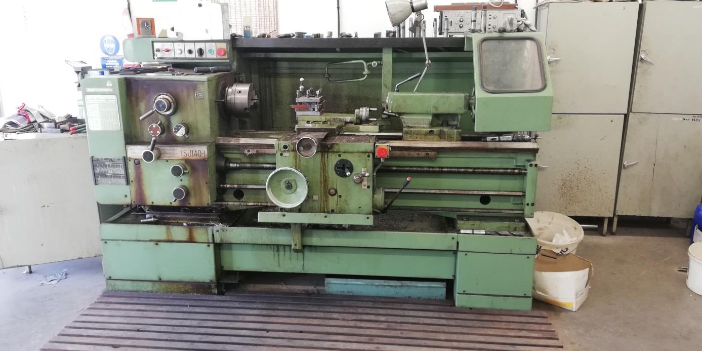
Fig. 4 Metal lathe TOS SUI 40
Table 1 Cutting parameters
Step number Cutting speed [m.min-1] RPM [min-1] Depth of cut [mm] Feed [mm.rev-1]
1 13.72 112 0.5 0.09 2 27.44 224 0.5 0.09 3 55.13 450 0.5 0.09 4 110.26 900 0.5 0.09 5 137.22 1120 0.5 0.09
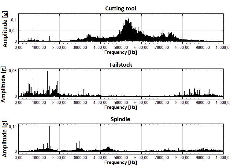
In Fig. 5 is shown an example of vibrations during turning with cutting speed 13.72 m.min-1 and in Fig. 6 with cutting speed 137.22 m.min-1 On Y-axis is acceleration of vibration an on X-axis is frequency of vibration. We measured vibrations on three parts of machine, on cutting tool upper graph, on tailstock middle graph and on spindle bottom graph in Fig. 5.
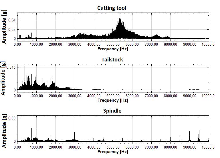
Fig. 5 Vibrations during turning with cutting speed 13.71 m.min-1
Fig. 6 Vibrations during turning with cutting speed 137.22 m.min-1
Roughness of machined surfaces, created during turning with different cutting speed is shown in Table 2.
Table 2 Roughness of machined surfaces
Cutting speed [m.min-1] Roughness Ra [µm]
13,72 27,44 55,13 110,26 137,22 4,35 4,07 3,53 1,53 1,48
CONCLUSION
In this paper we researched the influence of cutting speed on vibration and quality of machined surface during turning on metal lathe. We changed the cutting speed in five levels. From the graphs of measured vibrations and the measured roughness of the machined surface, it can be concluded that changing the cutting speed had significant effect to roughness of machined surface and vibrations. From Table 2 we can clearly see that increase of cutting speed from 13.72 m.min-1 to 137.22 m.min-1 brought almost 3 time better quality of machined surface. On the other hand increasing of cutting speed brought increasing of level of vibrations. The most significant was increase of vibrations on cutting tool. It can be caused by the fact that cutting tool has many times smaller weight than spindle or tailstock. Also it can be caused by type of cutting tool clamping. For the future, it would be useful to research the influence of cutting speed in a wider range and in more levels.
REFERENCES
[1] Adlink. 2020. USB 2405 datasheet [online]. 2020 [cit. 25 March 2020]. Available from: <https://www.adlinktech.com/Products/Data_Acquisition/USBDAQ/USB2405?lang=en> [2] Badiola, X., Iturrospe, A., Abete J., (2019) State–space analysis of mode-coupling workpiece chatter. In The International Journal of Advanced Manufacturing Technology [online], vol 103, pp 2773 – 2781 [cit. 2019-03-17]. ISSN: 0268-3768. Available from: <https://doi.org/10.1007/s00170-019-03737-8>. [3] Bejaxhin, A., Paulraj, G., (2019) Experimental investigation of vibration intensities of
CNC machining centre by microphone signals with the effect of TiN/epoxy coated tool holder. In J Mech Sci Technol [online], vol 33, pp. 1321–1331 [cit. 25 March 2020].
ISSN 1976-3824. Available from: <https://doi.org/10.1007/s12206-018-1232-3> [4] Kangalov, P., Beleva, D., (2016). A Research about Roughness of Sliding Friction
Surfaces of Couples Working in a Field with Modificators of Friction. Proceedings of
University of Ruse, 2016, vol. 55, book 1.1., pp. 84-89, ISSN:1311-3321 [5] Kuljanić, E., Totis, G., Sortino, M., (2008) AMST'08 Advanced Manufacturing Systems and Technology. Udine: International Centre for Mechanical Sciences. 666 s. ISBN 97888-85137-22-9 [6] Nikolov, M., Kangalov, P., (2014). Research Methods for Tribological Properties of
Restorative and Preventive Coatings in Different Lubricating Media at Sliding Friction. (2014) Acta technologica agriculturae, No 3, pp. 70...74, ISSN 1335-2555.