21 minute read
INGLEWOOD SANITARY TRUNK – USE OF SLURRY MICROTUNNELLING TO CONSTRUCT A LARGE DIAMETER SANITARY SEWER
North American Society for Trenchless Technology (NASTT) NASTT 2021 No-Dig Show Orlando, Florida March 28 – April 1, 2021
INGLEWOOD SANITARY TRUNK –

USE OF SLURRY MICROTUNNELLING TO CONSTRUCT A LARGE DIAMETER SANITARY SEWER

Patrick Ilasewich, AECOM, Winnipeg, MB Marvin McDonald, AECOM, Winnipeg, MB Chris Macey, AECOM, Winnipeg, MB Melanie Gray, City of Calgary, Calgary, AB
ABSTRACT Located in Calgary, Alberta, The Inglewood Sanitary Trunk (IST) is a 2,286/2,500 mm (90/98") reinforced concrete sewer which spans approximately 4,000 m (13,000') from the Bow River to the Bonnybrook Wastewater Treatment Plant, the City’s largest wastewater treatment plant. The IST upgrade will provide additional sanitary capacity for a total equivalent population of 1.1 million residents and support growth to the 2076 design horizon.
Construction of Phase One has been successfully completed, where closed faced slurry microtunnelling and sealed shafts were utilized to mitigate constraints and restrictions which would otherwise make the construction of a large diameter trunk sewer in this location impractical or near impossible.
Shaft construction to depths of 16m (52') consisted of seven sunk concrete caissons ranging in diameter from 8 to 11.5 m (26–38'), and one 11.5 x 8 m (38 x 26') secant pile shaft. Drive lengths through highly variable soils with high groundwater ranged from 250–860 m (820 – 2,822'). Most drives contained at least one 500 m (1,640') radius curve, some contained multiple curves, and one drive was on an entire curved alignment. The contractor mobilized three different Herrenknecht AVNs to the site. With the exception of one drive, all other drives came within project tolerances. The project contained four trenchless major railway crossings, and multiple utility crossings. In one instance a 900 mm (36") sewer was crossed with less than 150 mm (6") of clearance. In another instance an Art Gallery building was tunneled under with no damage to the structure or its contents. PROJECT DESCRIPTION The City of Calgary identifi ed the need for additional sanitary sewer capacity for the existing 15th Street trunks to meet future demands from wet weather fl ows and residential growth. These large trunks convey sewage fl ows from the northern half of the city of Calgary as well as from the communities of Cochrane and Airdrie.
The original concept proposed the addition of a third trunk along 15th Street SE from the Bow River to the Bonnybrook Wastewater Treatment Plant (BBWWTP), sized to accommodate future loads through the planning horizon of 2,076. Estimated additional capacity of 7.3 cubic metres per second was required, conveyed via a 2,400 millimetre (8') diameter pipe.
It was identifi ed early in preliminary design that the 15th Street SE corridor

would be a challenging route for numerous reasons, including: • It is already highly congested with regional utilities. • The corridor crosses a densely developed residential area near the
Bow River, which transitions to heavy industrial land use to the south. • The route crosses Alyth Yard, likely
Canadian Pacifi c Railways largest and busiest rail yard in Western Canada, known to have contaminated ground. • Portions of the original 15th Street
ROW have been closed with easements registered to or encroached by adjacent heavy industries. An alternate “offl oad” concept was developed that intercepted two major infl ows from the western parts of the City, including the Inner City Trunk (ICT) and the West Memorial (WM) trunk, which allowed the existing 15th street trunks to be used for additional fl ows from the northeast portions of the City. This concept allowed for development of alternate routes that would avoid this already congested and challenging right-of-way. This alternate route also allowed use of trenches construction which would limit community impacts. This alternate route shared a newly acquired right of way that was purchased from CN rail, for development of a new leg of the City’s light rail transit (LRT) system called the Green Line South East LRT (GLSE). This new route would pose its own unique challenges.
TRENCHLESS DESIGN During the design process, it became clear very on that in order to minimize community impacts, trenchless construction would be required. Depths of pipe cover ranged up to 17 m (56") the alignment crossed four major heavy railways, and crossed several major transportation routes.
The City of Calgary recently purchased lands for the GSLE LRT project, and was also eager for these lands to be utilized for the IST project as well. In order to use these lands and alignment, multiple curves were required to circumvent everything from an abandoned landfi ll to future LRT tracks and a tunnel.
The IST project was the largest microtunnelling project to be released in Calgary to date. A summary of shafts and drives is provided in Table 1 and Table 2.
Closed face slurry microtunnelling was selected for construction as it could mitigate these challenges. In order to reduce construction costs and ensure project success, the project was designed utilizing ASCE 36-15 – Standard Design and Construction Guidelines for Microtunnelling.1
GEOTECHNICAL CONDITIONS Ground conditions along the route are highly variable and contain high ground water. Large portions of the drives are in gravels and sands. Extremely hard cobles and boulders were to be expected. The ground water table in these areas is infl uenced by the Bow River and pump tests indicated dewatering for shaft construction and tunnelling was not feasible in most areas. Ground water levels were frequently above the tunnel horizon. Sealed shaft construction with closed face slurry microtunnelling will allow installation of the sewer through these complex soils without dewatering. An example of the typical ground conditions is provided in Figure 2.
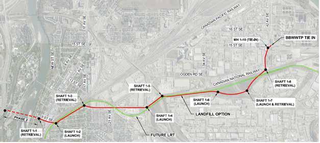
Figure 1. Selected Route Evaluated During the Design Phase.
SHAFT DEPTH (m) SOILS
1 7.1 Sand/Gravel
2 3 12.0 Gravel 7.4 Gravel
4 9.7 Gravel/Rock
5 10.6 Sand/Gravel
6 7 8 9 9.9 Mixed/Rock 13.9 Sand/Rock/ (CS/SI) 5.8 Rock (CS/SI) 3.6 Gravel
Table 1: Shaft Summary
GW m (BGS)
5 11 5 6 9
8 2
DRIVE LENGTH (m) SOILS
1 245 Sand/Gravel
2 3 454 Gravel 856 Gravel
4 259 Rock/Gravel
5 6 7 8 764 Rock 406 Cohesive Till/Rock 386 Sand/Rock (CS/SI) 98 Gravels
Table 2: Drive Summary
CURVES
1 1 2 0 2 1 1
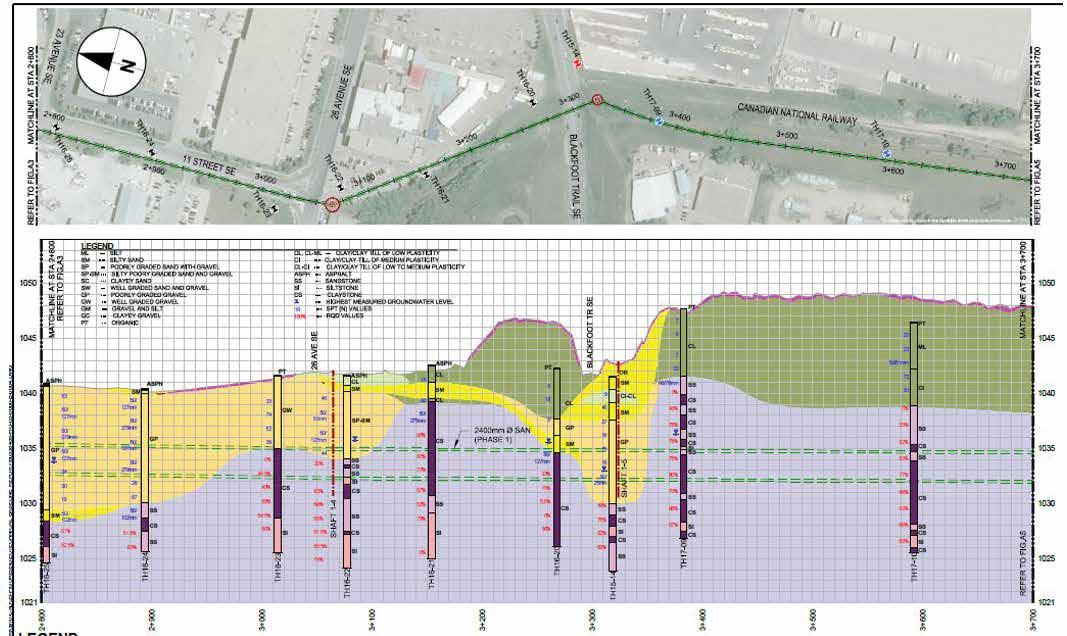
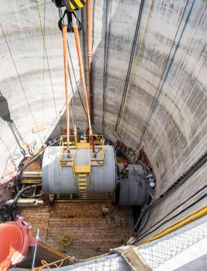
Figure 2. Typical Ground Conditions. Figure 3. Typical Sunk Caisson Shaft Used in Construction.
PREQUALIFICATION AND TENDER STRATEGY Due to the complexity of the project and the tight construction schedule a prequalifi cation program was utilized. The prequalifi cation was aimed at both the general and microtunnelling subcontractors. To work in the city of Calgary the general contractor was required to meet both City and Provincial safety requirements. Out of province contractors may have struggled with attaining the safety certifi cation prior to construction. This left them the option to team up with a local contractor.
The prequalifi cation program was released prior to the detailed design component of the project being completed. This provided advance notice to the microtunnelling industry of the upcoming project and ensured the contractors bidding on the project would have ample notice to have the required equipment available for construction.
The prequalifi cation program also benefi ted the project by ensuring the contractors ultimately bidding on the project would have the appropriate experience for successful project delivery. As part of the prequalifi cation evaluation, the microtunnelling contractors were required to demonstrate similar experience in the proposed pipe size, drive lengths, and curves. To qualify as a general contractor the contractor needed to demonstrate proper safety experience, bonding and management/fi nancial of a project of similar size and scope.
A total of 12 submissions were received for the prequalifi cation request, with fi ve contractors qualifying as general contractor and fi ve qualifying as microtunnelling subcontractor.
CONSTRUCTION The Contract for Phase 1 was awarded in October 2018 to Whissell Contracting Ltd. (WCL) as general contractor who also completed the open cut construction portions of the project as well as the live sewer tie-ins. Ward & Burke Microtunneling LTD (WBMCL) were retained as the microtunnelling subcontractor. Construction of the shafts began in January 2019 and Substantial Completion was achieved in November 2020, with a total construction value of approximately CDN $70 million.
The contractor chose sunk cast-inplace concrete caissons for seven of the shafts (Figure 3), with diameters ranging from 8–11.5 m (26–38') and constructed one 11.5 x 8 m (38 x 26') secant pile shaft. Secant piles where selected in this location as the shaft was constructed around an existing 1,800 mm ( 71") pipe. Tremie plugs were successfully poured at shaft locations where the shaft fl oors were below groundwater.
All shafts were constructed during regular construction hours to meet noise bylaw requirements and to not adversely impact the public. All shafts were successfully constructed without any signifi cant ground loss or impacts on adjacent structures, including an adjacent sound studio which was extra sensitive to noise and vibrations.
To meet the aggressive schedule, the contractor proposed a combination of 2,286/2,500 mm pipe to replace the proposed 2,400 mm pipe. This allowed the contractor to mobilize three different Herrenknecht AVN MTBMs to the site, and have enough pipe manufactured to meet the tight project schedule. A hydraulic analysis was completed to ensure project objectives were met, and the proposal was accepted. Tunnelling operations were allowed 24 hours/ day seven days/week. The contractor used a mix of single and double shifts throughout the project.
The contractor used an advanced alignment control system (VMT) to successfully navigate the numerous curves. Seven of the eight MTBM drives were successfully completed within 20 mm (3/4 inch) of the specifi ed alignment. On the one drives in question, the tunnel horizon increased to 200 mm above the intended invert, approximately 30 m outside of the retrieval shaft. Once noticed, the tunnel grade was corrected and brought into the shaft. Hydraulics were reviewed and no adverse hydraulic issues resulted.
On two separate drives the contractor chose to drive the MTBM into the shaft with either insitu material or backfi lled material in place up to the level of the surrounding groundwater rather utilizing
an exit seal (Figure 4). Once the TBM was pushed fully into the shaft, the annulus was grouted to form a seal at the shaft wall, The TBM was then excavated out and removed.
DESIGN CHALLENGES, INNOVATION AND LESSONS LEARNED
EPOXY COATED BELLS It was identifi ed in design that soils along the route were known to be potentially highly corrosive and abrasive. There was also a concern that stray current from the proposed electric GLSE LTR system could result in advanced corrosion of ferric metal elements of the pipe system. The mixed ground conditions containing boulders and cobbles with a Cerchar Abrasivity Index (CAI) of the boulders ranged from approximately 4.2 to 4.9, indicating that the boulders are extremely abrasive based on ASTM D7625-10 (AECOM 2017).2
The resistivity of soil and bedrock samples varied from 90 ohm-cm to 21,000 ohm-cm, indicating that the soil and bedrock units were essentially noncorrosive to extremely corrosive in certain areas. Soil and bedrock units were assumed to be extremely corrosive, and all metals in contact with the soils, bedrock and groundwater were to be designed for an extremely corrosive environment.
The typical microtunnelling pipe specifi ed for the project utilizes a steel bell ring which forms an integral part of the joint, compressing the primary gasket. In buried applications, steel pipe systems primarily fail through pinhole corrosion, often associated with breaches in dielectric coating systems. Failure of the joint ring by corrosion could result in infi ltration. To protect the bell rings from corrosion, the contract specifi ed the joint bands be coated with a minimum 0.4 mm (16 mils) liquid or fusion bonded epoxy dielectric coating, further protected with a minimum 0.75 mm (30 mils) abrasion resistant overlay (ARO) to ensure long-term performance of the joint.
The contractor proposed to factory apply the epoxy coating of the joint rings prior to casting the pipe. Due to concerns with compatibility with the pipe forms, the contractor proposed coating the bell ring with 0.91 mm (36 mils) of high abrasion resistant epoxy. The proposal was accepted with a requirement that the fi rst pipe of the drive would be pushed out after the drive to evaluate the effectiveness of the coating.
The pipe was pushed out after a drive of 406 m (1,332') which was entirely on a 500 m (1,640') radius curve. The ground conditions consisted of mixed conditions containing cohesive glacial till and bedrock. Visual inspection of the epoxy coating of the pushed recovered pipe indicated the coating performed well under the abrasive conditions experienced. However, some dis-bonding was identifi ed, likely due to lack of adequate adhesion due to insuffi cient surface preparation (Figure 5).
EXISTING 900 MM SANITARY CROSSING One of the project utility crossings involved an existing 900 mm wastewater pipe which had limited record information available. Surveys completed during preliminary design indicated there would be approximately 400 mm of clearance between the two pipes. Due to the upstream and downstream inverts of the IST being fi xed, this distance could not be signifi cantly increased. The clearance was conveyed to the contractor in the bid documents so the contractor could complete their own risk assessment and mitigation measures.
During the initial stages of construction, the contractor verifi ed the invert from the preconstruction survey was correct; however, the pipe invert contained approximately 250 mm of solid debris. That meant the actual invert was lower, resulting in a reduction of clearance to approximately 125 mm from the tunnel overcut and the existing pipe wall based on a standard wall thickness (Figure 6). As the pipe was approximated to be constructed in the 1950s, there was additional concern that the pipe may have been cast in place with a thicker base resulting in a direct confl ict with the tunnel. A subsequent CCTV inspection was arranged to confi rm fl ow levels and indicated what appeared to be pipe joints.
A risk mitigation session was arranged with the project team to review mitigation options which included: • Enhancing pipe support by ground improvements (jet grouting). • Temporary pipe support by open cut excavation followed by concrete encasement around the existing pipe after the tunnel was complete. • Installation of a CIPP liner or slipline in the existing pipe. • Use of a temporary pumped bypass during construction to mitigate risk of a pipe breach during tunnelling. Ultimately, the project team proceeded to install a CIPP liner into the 900 mm pipe as it was seen as the most cost-effective solution. The City had a CIPP contractor mobilized in the area already and was able
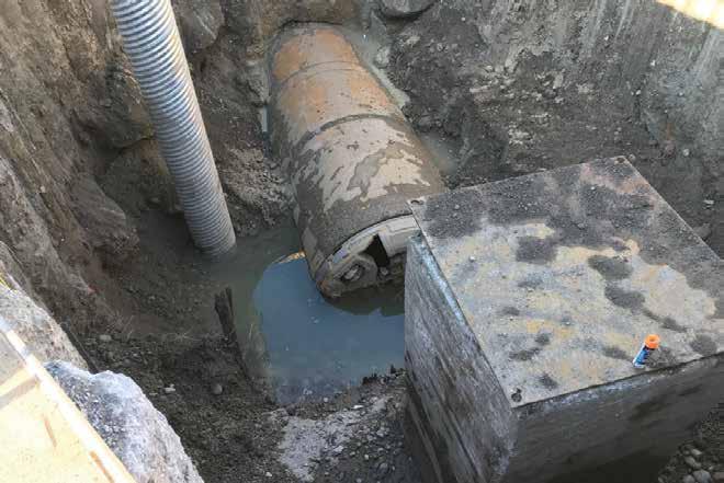
Figure 4. Retrieval of the MTBM in Insitu Shaft Material. Figure 5. Epoxy Coated Bell Ring After Drive.
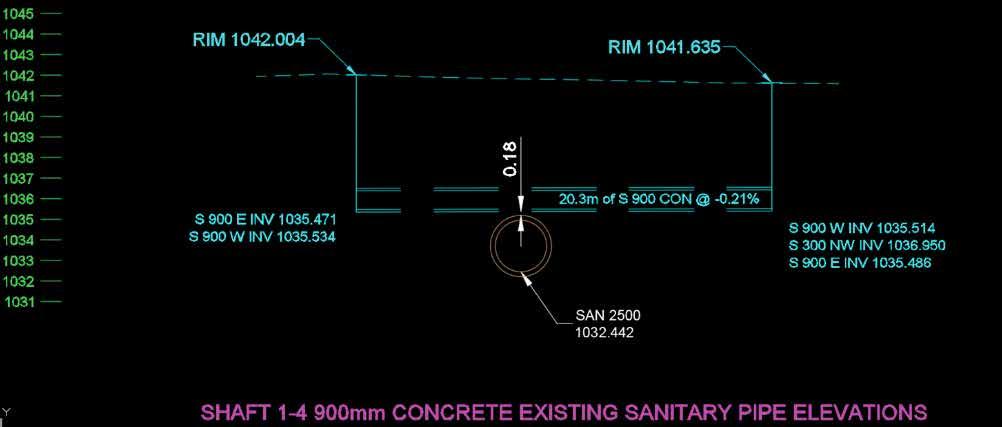
Figure 6. Minimal Clearance of Existing Pipe Crossing.
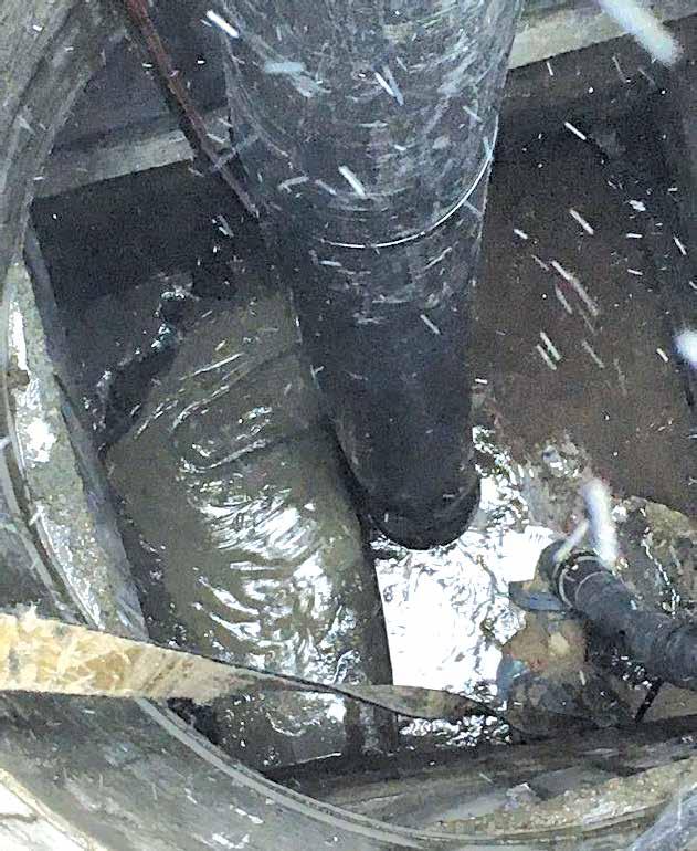
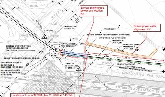
Figure 7. Frac-out in an Adjacent Manhole. Figure 8. Location of MTBM and Unknown Flow Path.
to line this section of the existing pipe without any schedule creep.
It was recommended that the CIPP liner be installed but not bonded to the concrete pipe to allow for greater pipe movement and to prevent any joint movement in the existing pipe refl ecting through the liner. As an additional safety measure the bypass used when installing the CIPP liner was left in place and utilized while the tunnel crossed the existing pipe. During construction, the pipe was monitored for movement, and follow-up CCTV inspections completed. No adverse effects on the existing pipe were noted.
Unknown to the project team was that the upstream manhole in the existing pipe, located approximately 5 m upstream of the crossing, was constructed with a cold joint between the base and wall slabs which resulted in a frac-out in the manhole (Figure 7). Tunnelling operations were suspended, the manhole was cleaned, and an additional concrete slab was poured to seal the joint. Tunnelling operations resumed with no further frac-outs at this location.
GBR FOR CONSTRUCTION CLAIMS To share construction risk with the contractor, a GBR was produced prepared in accordance with ASCE Suggested Guidelines for Geotechnical Baseline Reports for Construction.3 There were two instances in the project where the GBR was used to evaluate claims of unforeseen ground conditions.
The fi rst occurrence took place shortly into the longest drive of 850 m (2,789'). It was suspected by the contractor that the MTBM struck an obstruction and began to experience rapid wear of the face tooling and hard facing. The contractor did not believe the machine would be able to safely complete the drive and selected an appropriate location 350 m (1,148') into the drive to sink a rescue shaft to inspect and repair the face of the MTBM. Face tooling was replaced as well as hard facing of the face and crusher cone.
Tunnelling continued but again began to experience rapid tooling wear after an additional 100 m (328'). To minimize risk associated with an upcoming large diameter watermain crossing, the contractor chose to sink a second rescue shaft in a convenient location approximately 662 m (2,172') into the drive. Again, face tooling was replaced as well as the hard facing of the face and crusher cone.
The contractor fi led a claim for change in ground conditions. The drive was in mixed ground conditions and contained boulders and cobbles of extreme hardness and abrasiveness. Samples were collected at the site of the second intervention and analyzed for comparison to the conditions described in the GBR. It was determined that the ground conditions were consistent with those presented in the GBR. No evidence of an obstruction that resulted in the excessive wear could be found, but it was acknowledged an unknown obstruction may have been encountered. An amicable solution to claim was reached by all parties.
The second incident occurred shortly into a short drive where a frac-out occurred into a buried hydro vault housing electrical distribution cables for the area (Figure 8). The frac-out resulted in the power to an adjacent building being shut off, and a backup generator installed by the hydro utility for safety reasons. The vault was buried at surface with a granular base slab, and was located outside of the expected zone of infl uence of the MTBM.
The contractor fi led a claim for change in ground conditions. At the time the MTBM face was in mixed ground conditions of cohesive and granular soils and face pressures were determined to be within expected limits.
Review of the claim concluded that a fl ow path developed likely due to unknown ground conditions and the claim was settled.
FOUNDATION TIE BACKS During construction the project team became aware that a previously constructed building along the alignment was constructed with steel foundation tie backs to support the building shoring. Upon review of the available records, the extent of which tie backs were removed could not be confi rmed (Figure 9) . This posed serious risk to the tunnelling operations as there was potential to strike tie backs in 15 locations. Adding to the risk was the drive started with crossing of Canadian Pacifi c Railway Mainline coming out of Alyth Yard. Any potential tie back strikes could result in the MTBM being stopped under the CPR mainline.
A risk mitigation meeting was held with the project team. The alignment was modifi ed
TRUSTFUL PARTNERSHIP IN MICROTUNNELLING
We look back on 40 years of experience with AVN technology, 1,500 machines built, with up to 4 meters inner diameter, and countless successfully completed pipe jacking projects by our customers. With service from North America and reliable tunnelling technology we do our best to continue the joint success story. herrenknecht.com/en/avn
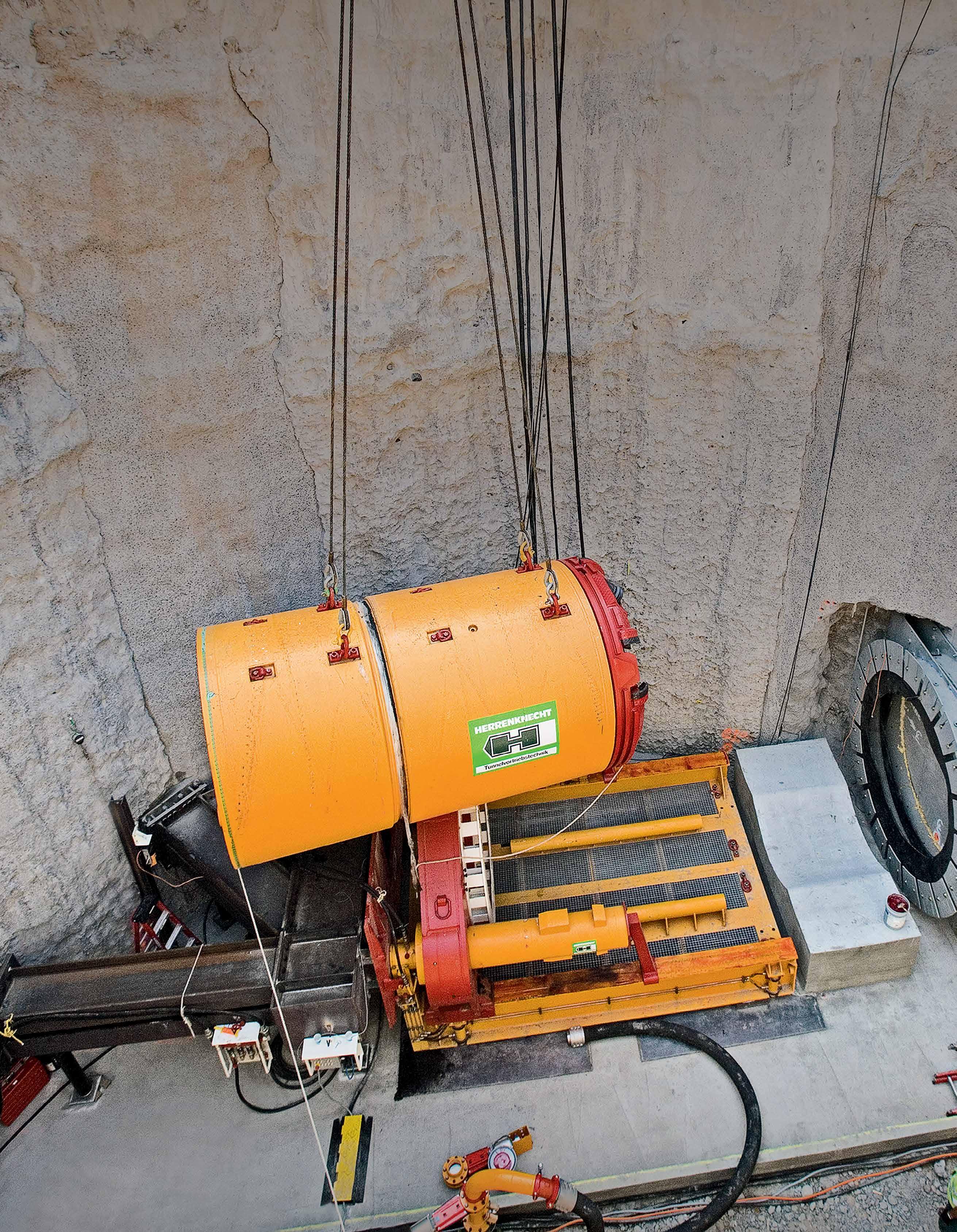
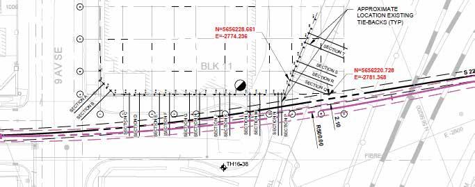
Figure 9. Potential Tie Back Locations.
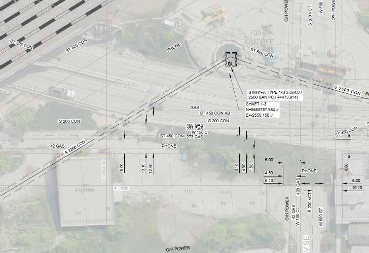
Figure 11. Alignment Under Art Point Building. Figure 10. Tie Back Recovered in Slurry Pump.
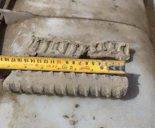
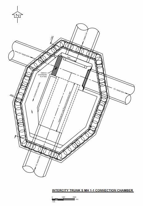
Figure 12. Upstream Shaft with Bypass.
slightly to provide more clearance to the tie backs where possible. It was decided that a narrow slot be excavated with a trench box along the alignment to dig and remove any potential tie backs located in the road right of way. No tie backs where found in the road right of way and the MTBM successfully navigated this section. The MTBM did, however, strike a tie back just outside of the area excavated with the slot but no damage to the machine resulted (Figure 10).
ART POINT BUILDING The City of Calgary acquired lands for the future GSLE project, with the goal of maximizing land use for other City projects. The IST utilized these lands where possible and paralleled the proposed LRT alignment. Originally the Art Point building was being considered for demolition to make room for a future LRT station which would provide ample room for the IST alignment. However, during the design phase it was decided that the building was to remain. Due to confl icts with a future LRT station there was no room to move the IST alignment. After a site investigation, it was determined that the building was a slab on grade and the potential for a piled foundation was low. After a risk mitigation review it was decided to leave the alignment in its current alignment and tunnel under the north-east corner of the building (Figure 11). Vibration and settlement monitoring was specifi ed in the contract placed at this location, and showed no adverse effects when the tunnelling was completed under the building.
UPSTREAM TIE-IN SHAFT The upstream tie-in shaft for Phase 1 of the project connects to the existing 1,800 mm diameter ICT. The IST will also be extended in the future to the north from this tie-in location. It served as a retrieval shaft in Phase One and will be used as a retrieval shaft in the future Phase Two.
This shaft is located at the north end of the project in a dense residential neighborhood. Minimizing disruption of the community during current and future construction activities was a primary concern of the client.
Connection to the existing ICT was also a design concern. This trunk conveys approximately 1 cubic metre per second dry weather fl ow.
With a goal of minimizing future construction footprint, and safe connection to the existing trunk on minds, a unique shaft and chamber design was developed which included a suitable internal bypass fl ume to be used during connection of both Phase One and Two construction, and removable benching to facilitate removal of a TBM during future construction (Figure 12).
The shaft was designed as an 8 x 12 m oval. The contractor proposed construction of a 11.5 x 8 m (38 x 26') secant pile shaft in this extremely congested area as indicated in (Figure 13). The shaft was sized to house the permanent chamber structure, fl ow bypass, and retrieval operations for both phases.
During Phase One the MTBM was driven into the shaft and retrieved with the existing 1,800 mm (36") in service. This permitted both the chamber construction and retrieval operations to be completed in dry conditions. The bypass was activated along the west side of the chamber to allow the removal of the existing pipe and installation of the temporary benching and slide gate on the east (downstream) side of the 1,800 (36").
The bypass was left in operation to permit retrieval on the MTBM in dry conditions, after which it will be abandoned in place.
CONCLUSION Completion of construction of Phase One of the IST demonstrates how the proper selection of trenchless construction technology results in a successful project. The project faced many complexities ranging from complex soils, high groundwater, and curved alignments, all of which closed face slurry microtunnelling construction was able to mitigate. The IST project pushed the acceptable limits of microtunnelling. From tunnelling under a building to long, multiple curved drives, many lessons were learned which will help guide the success of future microtunnelling projects. REFERENCES 1. American Society of Civil Engineers (ASCE) - Standard Construction
Guidelines for Microtunnelling (36-15). 2. American Society for Testing and
Materials (ASTM) D 7625-10 (2010)
Standard Test Method for Laboratory Determination of Abrasive Rock
Using the CERCHAR Method Policies and Priorities. 3. American Society of Civil Engineers
ASCE (2007) Geotechnical Baseline
Reports for Construction Suggested
Guidelines.
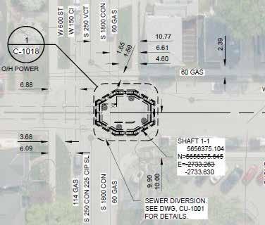
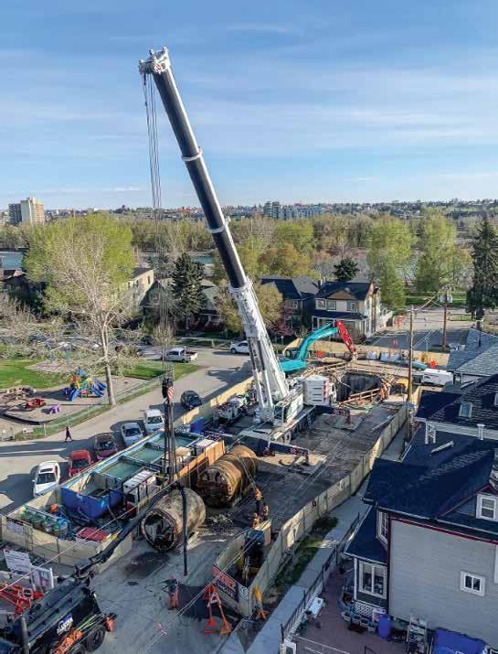
Figure 13. Upstream Shaft Layout l.
