12 minute read
NATIONAL POTY: CONSTRUCTION OF THE LARGEST SOLID WALL HDPE OUTFALL IN NORTH AMERICA – MCLOUGHLIN POINT WWTP OUTFALL, VICTORIA, B.C
CONSTRUCTION OF THE LARGEST SOLID WALL HDPE OUTFALL IN NORTH AMERICA –McLoughlin Point WWTP Outfall, Victoria, B.C.
Marvin McDonald, AECOM, Winnipeg, MB; Jordan Thompson, AECOM, Winnipeg, MB; Robin Dill, AECOM, Chelmsford, MA; Chris Macey, AECOM, Winnipeg, MB
INTRODUCTION
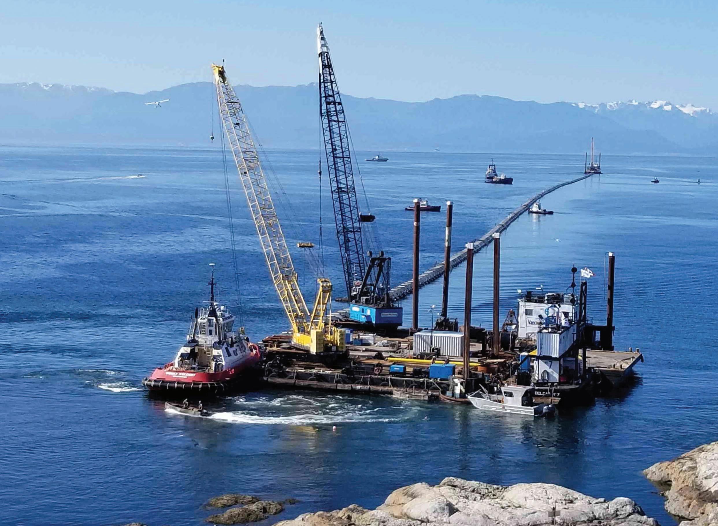
AECOM and its Joint Venture partner, Graham Construction (AGJV), designed and facilitated construction of a new ocean outfall, as part of the new McLoughlin Point Wastewater Treatment Plant in Victoria, B.C. The outfall is 1.92 kilometres (1.2 miles) long, and is primary constructed with 2,250 millimetre DR26 High Density Polyethylene (HDPE) pipe. This is the largest solid wall HDPE outfall in North America. The construction of the project was supported by our subcontracting partners Michels Canada and Vancouver Pile Driving Ltd.
The design and construction of the outfall features several unique and innovative concepts. The outfall was constructed in two distinct segments, a 120 metre long inshore segment, constructed with steel pipe by “wet exit” microtunnelling, and an 1,800 metre long offshore segment, constructed with HDPE pipe and installed by “float and sink” construction. This article will provide an overview of the design considerations utilized for the project, and an overview of the outfall fabrication, assembly, and deployment of the two specialized construction areas: the inshore and offshore segments.
DESIGN
Performance specifications for the plant required the outfall and diffusers required an ultimate design capacity of 438 mega litres per day (MLd) (5.1 cubic metres per second, [cms]). The range of flows over the life of the outfall, including diurnal and seasonal flow variation is highly variable, as indicated in Table 1. The high range in flow was a design challenge in selecting a pipe size that would provide specified scour velocities through the initial operational periods, and meet the ultimate long-term demands.
Table 1. Design Effluent Flow Rates
Commissioning
Ultimate Min Max Min Max
Flowrates MLD M2/s
43 0.5 381 4.4 58 0.67 438 5.1
The resulting design resulted in selection of a 2,250 millimetre HDPE pipe, with an internal diameter of 2,076 millimetres. It was imperative through detailed design to ensure headlosses along the pipeline from the plant to the diffusers were minimized.
The maximum available head at the discharge point at the plant was limited due to by-law criteria limiting the building height of the wastewater treatment plant.
Near and far field diffusion modelling resulted in design of a 210 metre long, 36 port diffuser, located in 60 metres of water. Design specifications required a minimum Froude number of 2 to prevent sea water ingestion during lower flows. This would have required initially closing several ports that would need to be open over full effluent flow development. To eliminate the need for sequential port commissioning over time, 200 millimetre wide bill “duckbill” or pinch valves were selected for the diffuser port exits.
The offshore segment was designed to resist movement by hydrodynamic and current forces present at the site. The initial specified valves are presented in Table 2. Table 2. Hydrodynamic Design Requirements
Parameter Value
Maximum Wind Speed 110 kph Significant Wave Height 4.3 m Wave Period 7 seconds Current Speed (Maximum) 1 m/s (2 knots) Current Direction Generally east or west
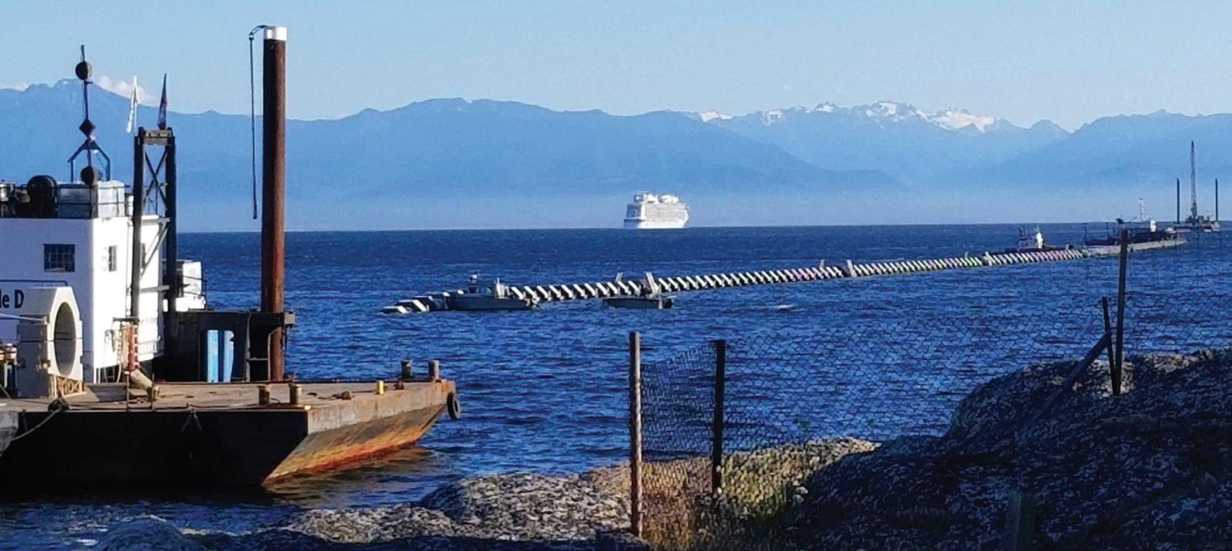
Table 3. Hydrodynamic Stability Summary information and completed a wind hindcast model, based on 125 years of record at nearby weather stations. Through statistical analysis, a 100 year wind speed and direction joint probability was completed, and displayed in a wind rose.
From this data, a wave estimation was completed using MIKE 21 Spectral Wave Model SW. This wave model resulted in a 100-year return significant wave height of a maximum of 3 metres from the southwest. This reduction in significant wave decreased design weight requirement considerably.
Using the significant wave, plus the specified design currents of 1 metre per second (m/s), a hydrodynamic stability analysis was completed. The analysis was completed generally using DNV F109 On-Bottom Stability Design of Submarine Pipelines. A summary of the hydrodynamic
CONSTRUCTION – INSHORE SEGMENT
The inshore section from the new treatment plan to the ocean consisted of a 120-metre (394-ft) long, “wet-exit” microtunnelling drive which was constructed with a 2,120-millimetre (6.95-ft) steel pipe section with a 25 millimetre pipe wall thickness to safely resist installation jacking forces. The pipe was driven through highly abrasive granodiorite bedrock. The pipe selected
output is provided in Table 3. AECOM reviewed the available
Depth
(m) 15 20 25 30 35 40 45 50 55 60
Peak Horizontal Load (Fy) N 4554 2826 2065 1642 1433 1312 1260 1225 1201 1186
Peak Vertical Load (Fz)
N 1852 1911 1572 1373 1256 1181 1134 1102 1061 1067 Friction Factor (μ) 0.6 for Silt 0.43 for Clay Buoyant Unit Weight of Concrete Required (SF=1.5)
Unitless (kg/m) 0.60 1879.33 0.60 1466.20 0.60 1220.39 0.43 1247.50 0.60 1010.87 0.60 968.62 0.60 948.05 0.43 1057.75 0.43 1046.31 0.43 1038.70
Mass of Pipe per Unit Length (Including Concrete Collars)
(kg/m) 1443.60 1012.46 766.66 793.77 557.14 514.88 494.31 604.02 592.58 584.97
Mass of Weight as % Pipe Displacement
% 47% 36% 30% 31% 25% 24% 23% 26% 26% 25%
% Air to Achieve Neutral Buoyancy
% 54% 41% 34% 34% 27% 26% 25% 29% 28% 28%
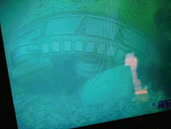
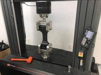
Figure 3. Quality Control Testing
for the jack was Permalok® steel pipe in 3 metre lengths. The Permalok® pipe utilizes a specialized stab fit connection system, which eliminates welding during the jacking process. The pipe was protected from corrosion through use of an abrasion resistant overlay (ARO) epoxy, and the bore annulus was pressure grouted with a specialized grout containing a calcium nitrite corrosion inhibitor. The interior of the pipe was provided with a polyurethane coating conforming to AWWA C222 for corrosion protection. A cathodic monitoring lead was also added to the pipe for long-term monitoring of the steel pipe elements. On completion of the drive, the pipe joints were seal welded to ensure a leak proof product, and the weld holdbacks were repaired.
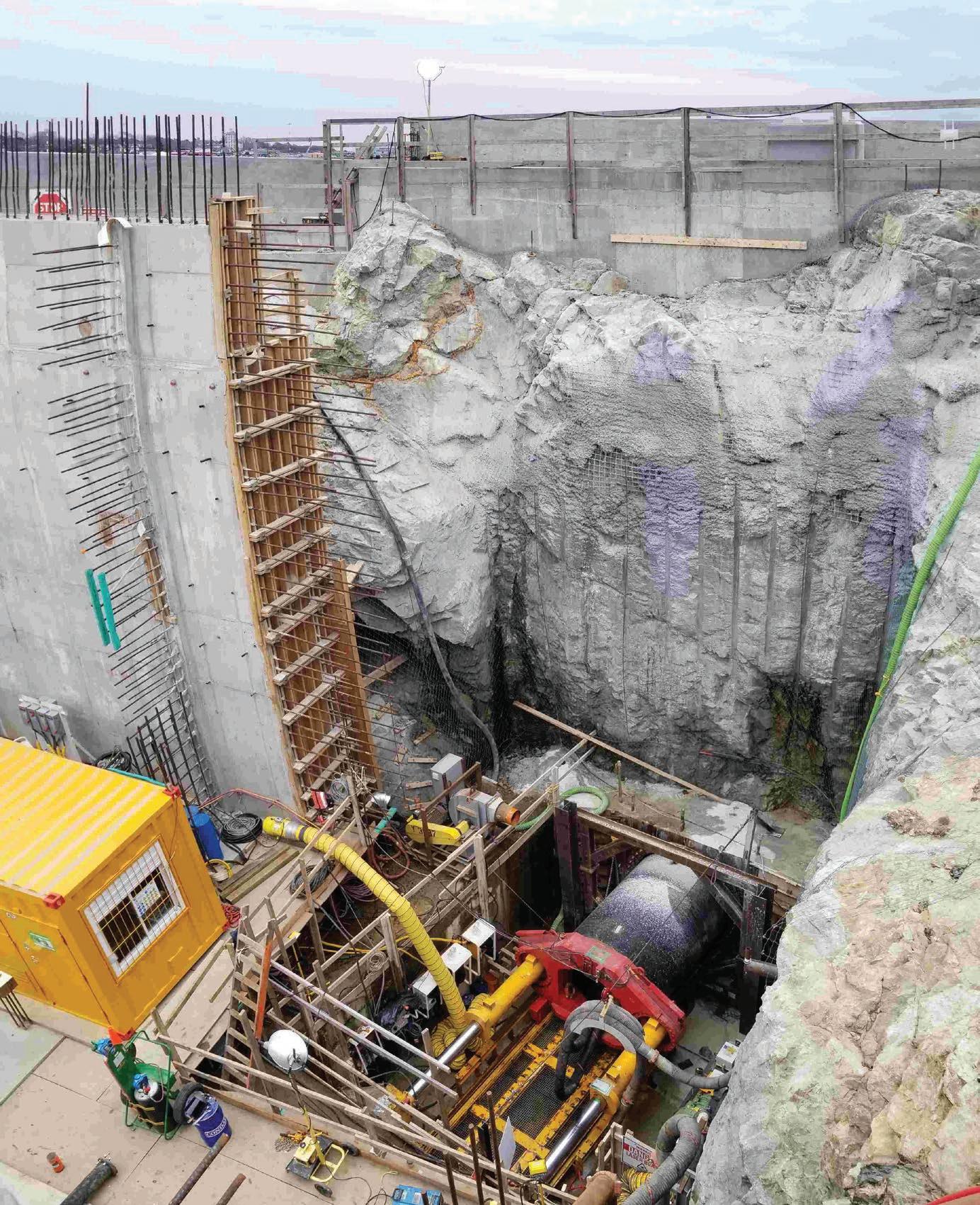
The drive started from an inshore blasted jacking shaft at a depth of approximately 12 metres (40 feet) below ground as shown in Figure 1, to a blasted offshore marine trench at a water depth of approximately 12 metres (40 feet), Figure 2. This section of pipe was installed by a Herrenknecht AVN MTBM. Production was in the order of 3 metres per day, with one shift.
The pipe used in the drive included a custom designed bulkhead door behind the TBM, which allowed for the TBM to be removed in the wet, and floated to surface. The connection of this system required a specialized 3-ring internal flange for connection of the bulkhead pipe to the product pipe to minimize intrusion of the internal flange to approximately 60 millimetres, to reduce headloss. The inshore end on the pipe featured a blind flange which protected the treatment plant site from flooding during constriction. On completion of the plant construction, the outfall chamber was flooded, and the blind removed by divers.
OFFSHORE SEGMENT
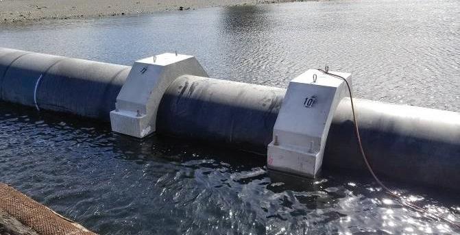
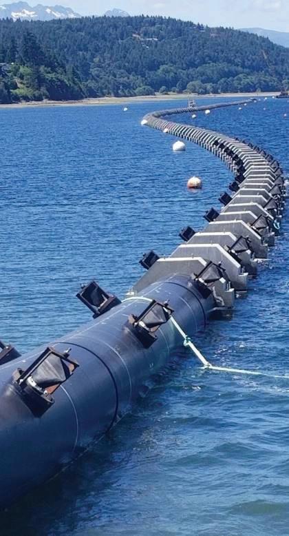
The offshore section of the outfall was comprised of concrete weight ballasted 2,250 millimetre HDPE pipe, installed by “float and sink” methods, in water depths up to 62 metres (203 feet) deep. The float and sink installation was approximately 1,800 metres (5,900 ft) long, and included a 210-metre (690-ft) long, 36 port diffuser. The 2,250 millimetre HDPE pipe consisted of a short inshore section of DR 21 pipe (107 millimetre wall), and the balance utilized DR 26 pipe (87 millimetre wall thickness). This is the largest deployment of solid wall HDPE and the largest solid wall HDPE outfall in North America.
The initial pipe selected for this project during the initial bid was coated, lined, and cathodically protected steel pipe. During the design process, larger diameter, high-performance HDPE pipe, manufactured to European ISO standards, became available in North America in 2018. The change to HDPE pipe was premised on its long-term performance in the corrosive sea water environment, increased seismic resiliency, and its ease of construction.
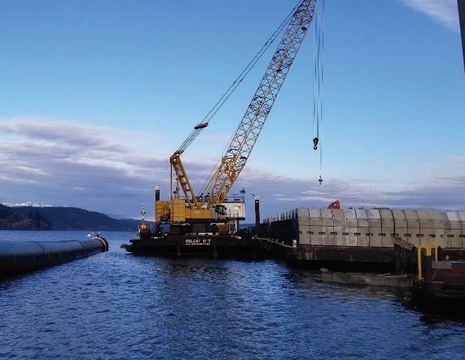
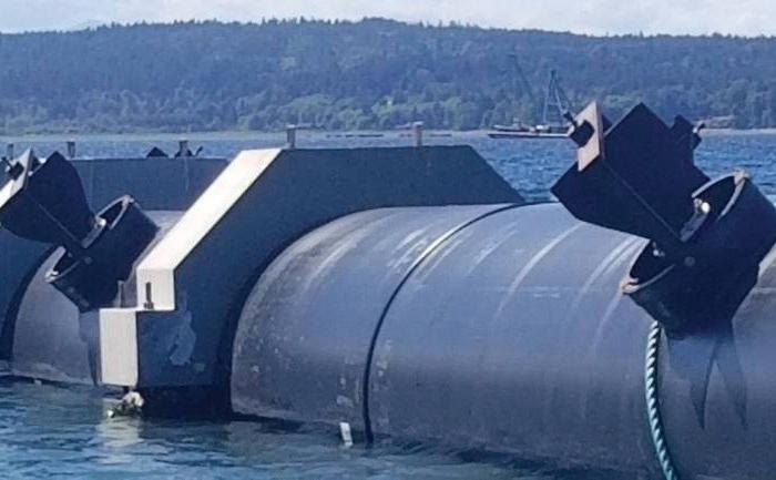
Figure 5. Diffuser Details
The size of solid wall HDPE pipe in North America, until recently, was limited to 1,600 millimetre diameter.
To facilitate the sinking operation, an installation sink analysis was completed to control the radius of the pipe bending during sinking. The analysis indicated that an end pull force of 100 metric tonnes was required, plus a 2 bar internal pressure, to control pipe bending to an acceptable level. A DR 26 pipe was selected after review of the dynamic installation forces required for this project.
The pipe was supplied by ISCO, and manufactured by Agru America in Charleston, SC, in 16 metre sticks. AECOM attended weekly pipe quality assurance sessions through the manufacture process (Figure 3).
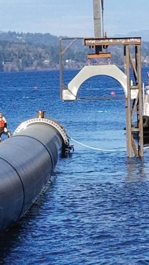
The selected pipe ballast was 4.75 cubic metre precast concrete weights, spaced from 4 to 6 metres apart. Overall, a total of 350 ballast weights were installed. The weights were designed for the longterm stability mass required, as well as the installation forces expected during deployment. Each weight design is approximately 11,400 kilograms. The weights were designed to withstand a 2 bar internal pressure during deployment, and a maximum 3 bar test pressure post assembly.
Pipes were transported by truck to the assembly site, in Nanoose Bay, north of Nanaimo, about 180 kilometers by sea from the project site. HDPE fusion was completed on shore in a weatherresistant enclosure. Typically, two segments were fused per day.
The pipe was towed off the fusing machine, into Nanoose Bay, where the ballast weights were installed by crane (Figure 4), using a special frame designed by Vancouver Pile Driving. Each weight has a mass of approximately 11,400 kilograms.
Post pipe assembly, the pipe was pressure tested to ensure hydraulic integrity. The predicted pipe strain during the pressure test phase was an increase of 16 millimetres of pipe diameter, based on an estimated time based elastic modulus of 400 MPa for a four-hour test period. The actual measured pipe strain diameter during the 3 bar pipe expansion phase was an increase of 17 millimetres, which reduced to approximately 11 millimetres when test pressure was reduced to 2 bar. This measured pipe strain closely matched the predicted values.
The diffusers (Figure 5) feature 200 millimetre duckbill valves to prevent sea water intrusion into the outfall. This feature was selected to maintain adequate design diffuser velocities over the time dependent capacity development of the treatment system. The pipe diffuser section designed with a unique port sealing system that allowed it to be installed in one operation as part of the main pipe string. Traditionally, the diffuser section of an outfall is installed as a separate operation. A gasketed internal sealing plate was used to close off the diffuser ports during installation, to allow the pipe to be pressure tight during install. To accommodate the duckbill valves, a unique framing system was constructed to allow the sealing plate to be tensioned to the inside of the pipe. After deployment, the inner plate was removed by an ROV, allowing the diffusers to function as designed.
Materials and hardware for the project, including weight bolts, flanges, and fasteners were selected to provide corrosion resistance and project economies. Flanges included use of super duplex stainless steel flanges and fasteners. Due to the cost of these specialized fasteners, only enough corrosion resistant bolts were used to provide long-term sealing performance on bottom, with the balance of the fasteners being more economical galvanized mild steel. Similarly, bolts used in attaching weighs for pipe included a 50% mix of silicon bronze fasteners and marine-grade cold water anodes, and galvanized mild steel. The mild steel fasteners were required to ensure adequate clamping of weights to the pipe during install, and the silicon
bronze to allow for long-term performance to hold the weights in place on bottom for duration of the 75-year design life.
The intertidal and subtidal zone was protected from anchor drag to a depth of 15 metres by installation of a riprap protection system. The riprap was designed as a filtered system progressing in size from a 75 mm sized material around the pipe and anchors to the surface riprap course of 900 mm sized rock.
The project also required habitat compensation due to the construction footprint. This was achieved through construction of intertidal reefs to augment the fish habitat. The berms were partially constructed with blast material from the tunnel exit shaft area. The design also featured installation of 20 bridges across the pipe, to allow for migration sea life across the pipe, should the pipe become embedded in the sea floor and restrict movements of species.
The offshore pipe was fabricated and installed in two segments. A short inshore segment approximately 40 metres in length was installed first. The design alignment required a 30 degree bend just offshore to align the pipe to its final location. This section was sunk as an open-ended pipe, using two cranes with spreader bars to lower the pipe to bottom. The longer second segment was sunk in place, using a “float and sink” operation.
The pipe was towed to site from Nanoose Bay on July 24 and 25, and was successfully deployed on July 25 and 26. The worksite was extremely congested with the Victoria cruise ship dock immediately to the east, and Victoria Harbour sea runway immediately to the north. Initially, the deployment was scheduled to commence at approximately 5 AM on July 25, but several delays resulted in deployment commencing in the late afternoon, which was completed at approximately 5 AM on July 26.
SUMMARY
AECOM and its Joint Venture partner Graham Construction (AGJV) designed and facilitated construction of a new ocean outfall, as part of the new McLoughlin Point Wastewater Treatment Plant in Victoria, B.C. The construction of the project was supported by our subcontracting partners Michels Canada and Vancouver Pile Driving Ltd.
The project consisted of two unique construction segments. The inshore segment of 2,120 millimetre diameter steel pipe, from the treatment plant to approximately 120 metres offshore, was designed and constructed by microtunnelling through bedrock, using a “wet exit” technique whereby the TBM and carrier pipe were pushed out under the ocean, and the TBM retrieved by diver.
The offshore segment was constructed of 2,250 millimetre diameter HDPE pipe, weighted with precast concrete weights, and installed by a “float and sink” method. The 2,250 millimetre HDPE pipe is the largest solid wall HDPE outfall in North America, and featured a unique diffuser port design that allowed the diffuser to be installed as part of the main pipe.
This project was executed using design-build delivery. The designer, microtunnel, and marine subcontractors closely coordinated and optimized design and construction details to successfully complete the construction.
REFERENCES
AECOM. (20188) – McLoughlin Point Wastewater Treatment Plant – Basis of Design Report – Outfall
