17 minute read
Engineering Considerations for Greases Used in Robotic Applications
Michael D. Holloway, 5th Order Industry, LLC Highland Village, TX 75077 | 214-450-7864, holloway@5thOi.com
Adam M. Smothers , Aerospace Lubricants, Inc. Columbus, OH 43228 | 614-620-5823, adam@aerospacelubricants.com
Rich Wurzbach , MRG Laboratories York, PA 17401| 717-843-8884 rwurzbach@mrgcorp.com
Multi-axis robotics are a relatively new application in the world of manufacturing assembly lines. Often when a piece of equipment is brought on line, its lubrication requirements are not readily understood until failure occurs and reliability data are established. Guess work combined with fundamental concepts are used until the overall reliability entitlement and product performance criteria are established. This paper describes the logic of how a grease is selected and then maintained to meet the challenges of robotic applications. The information in this paper will help end users select and maintain lubricants for their robotic devices and avoid failure.
Industrial Robotics
The use of robotics and automation continues to grow more prevalent across industries, particularly in manufacturing, as companies are realizing the full potential of its ability to reduce costs, boost production, and deliver greater efficiency and competitiveness. Typical industrial robotic applications include welding, painting, assembly, product inspection, and testing. As the technology has progressed, automation has demonstrated exponential improvements in endurance, speed, and precision, and more sensitive applications in medical and other high-tech sectors are becoming common. With highly choreographed, programmed movement on two or more axes, bearings play a major role in the motion control aspect of this technology. The use of high-precision bearings is an integral consideration for those tasked with designing and maintaining these applications. Bearing life and performance demand that the correct type, material, and lubrication are specified. The advantages of robots are precision, speed, and strength. These demands challenge the bearings and, ultimately, their lubricants.
Industrial robots provide precise motion in multiple dimensions, from single axis to multi-axis applications. The arm connections of a robot determine the number of axes. For example, an arm with a 2-axis configuration travels in an x-y plane in a Cartesian coordinate system (Fig. 1). The device on the end of a robot’s arm, sometimes referred to as an ‘end effector’, performs work. Robots with 2-D configurations are commonly used with end effectors that pick and place parts, dispense a fluid such as ink or adhesive, insert screws or rivets, and perform inspections. Devices that insert screws or rivets or perform inspections can be fitted to robot arms with 2-axis configurations. Often, the arms are controlled by motor-driven rack-and-pinion gears, chains and sprockets, or guide wheels with wires or bands. There have been advances in hydraulic and pneumatic applications for 2-axis configurations.
Robotic arms with 3-axis configurations (Fig. 2) are utilized in applications that require fast and intricate movements. An arm with a 3+axis configuration (Fig. 3) can work in 3 dimensions. In multi-
axis units (Fig. 4), the arm can displace the end effector tool through a wide range of motion These robots vary in size from fitting on a desktop to standing many meters tall. They are tasked with various aspects of assembly as well as inspection. Each axis requires a bearing (Fig. 4), and the strain on the bearings can be significant. There is little tolerance for error. Often, if the arm alignment is off by a few hundred microns, then the assembly will suffer and the part may be scrapped. Bearings play a significant role in the precision of these robots, and the lubricant has a direct influence on bearing performance and failure.
Figure 1. 2-Axis Figure 2. 3-Axis
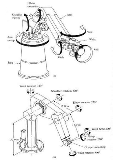
Figure 4. Multi-Axis Rotation Figure 3. 3+Axis
Bearings Used in Industrial Robotics
The advancements in electric motors, actuators, and sensor technology have increased the number of applications of robots. The bearings are responsible for moving the arms in a precise fashion. Bearings are typically made of chromium steel or ceramics. Roller and ball bearings as well as thrust bearings are all found in robotics applications. Thin section bearings are highly popular
Thin section bearings deliver higher speeds, improved efficiency, and higher levels of design flexibility. Reduced weight is achieved by the small difference in size between the internal and external rings. While the thin section configuration offers advantages, the increased flexibility makes the bearing susceptible to dimensional changes that could impact lubricant film formation. Material selection and attention to manufacturing are essential in bearing production. If the rings are not perfectly formed, even a minute discrepancy will prevent the bearing from turning smoothly, which will increase friction, wear, and vibration. These bearings can be open, shielded, or sealed in SAE 52100 chrome steel or grade 440 stainless steel. They are designed to withstand some radial loads as well as moderate thrust loads in both directions. Some of the smaller thin section bearings are also available with a fiberglass-reinforced nylon high-speed synthetic retainer.
Single-row deep groove ball bearings, with sizes ranging from miniature to extra-large, are used for most applications. Thin section bearings are often designed into robotic arm joints due to their low mass, space-saving construction, and high-speed capability. Roller bearings are usually the first choice for heavy-duty requirements. Slewing rings are a common selection for the main rotation and associated lift equipment. Hybrid (ceramic balls with stainless steel rings) and full-ceramic bearings can be alternatives for operations in harsh environments. Depending upon the operating environment, the load, and speed can influence the selection of the bearing alloy. For example, 440C stainless steel alloy can be used in harsh or corrosive environments as well as medical, food, or chemical processing applications.
Lubrication
The lubricant can affect the performance, energy efficiency, wear, and service life of a bearing. It is important to choose an appropriate lubricant for each bearing in every application. Lubricant selection depends on the bearing type and size, operating speed, environmental conditions, and other factors. Many bearing manufacturers, lubricant suppliers, and organizations provide guidance for bearing lubrication (see References).
The grease of choice for robot joints is typically a low-flow NLGI 0 or NLGI 00 grease. An NLGI 2 grease may be too stiff for low-torque or fast-moving bearings. The base oil viscosity range is dependent on the equipment design and operating parameters. Mineral or semi-synthetic base oils with viscosity ranging from 40 to 175 cSt are typically used in these greases. But the optimal operational viscosity should be determined first. This requires the determination of the bearing speed factor, ndm . The bearing speed factor is the product of the rotational speed, n, and the pitch diameter, dm. The bearing speed factor can be calculated as shown in Equation 1.
nd m = n (ID + OD)/2 Equation 1. Bearing Speed Factor
where n = shaft speed (rpm) ID = bore diameter (mm) OD = outside diameter (mm) The value of nd m can also help engineers decide whether to lubricate a bearings with oil or grease, Table 1.

Table 1. Bearing Speed Factor, nd m, for Lubricated Components
Table 1 is based upon material that was published in Lubrication Fundamentals by D. M. Pirro and A. A. Wessol, 2nd
Edition, Marcel Decker, Inc. (New York, NY), 2001, page 197, Copyright © 2001 by Exxon Mobil Corporation Film formation by the base oil is strongly dependent on the molecular structure of the oil, including molecular shape and flexibility. These characteristics also influence the ability of the film to undergo shearing at high applied pressures. Shearing and reduction of friction are favored by the alignment of linear and flexible molecules.
The grease thickener properties have a significant influence on flow. Certain types of thickeners adhere on the race and rolling element surface and form a thin residual layer of thickener particles while other studies suggest that during the lubrication process, grease is mechanically degraded and transforms into a Newtonian suspension of thickener particles in oil, with a higher viscosity than that of the base oil. The thickener chemistry, the concentration, and the thickener particle morphology have a strong influence on film formation, and they consequently affect friction by determining the lubrication regime. A grease with a service temperature from -40 to 150 °C would be most suitable as this range reflects the variety of applications in which a robot is most likely to be used, from refrigeration to locations near a furnace. It may also be necessary to select a food grade grease if the robot is going to be used in food or beverage production or packaging. The right grease choice will result in a bearing that spins freely, which will reduce the power consumption of the machine as well as its long-term maintenance costs.
Grease Testing
Various standardized tests have been developed to determine and verify the performance characteristics of lubricants. A short list of the ASTM tests for characterizing grease is presented in Table 2. When selecting a grease for a specific application, the overall set of properties of the grease should be considered. Table 2 describes each test method and how to interpret the test results. It is essential that the end user evaluate the data prior to using a grease in a given application. The grease supplier will typically provide the customer with the test results for their product.
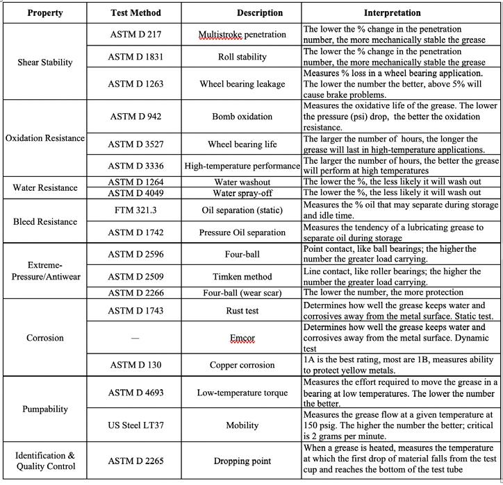
Table 2. Tests for Characterizing Greases Robotics Applications Table 2 was compiled by Michael D. Holloway It must be understood that these grease tests only provide a roadmap for choosing a product. Selection of the optimal grease for an application can be carried out through a field study. Choosing the best grease from a field trial can be difficult. It is helpful to develop a spreadsheet for comparing the evaluated greases. Table 3 is an example of such a comparison. There is a challenge in trying to understand which test or tests best mimic the environment that the grease will be subjected to. In order to make an accurate and informed decision on grease selection for any given application, a few tests stand out as good barometers of performance.
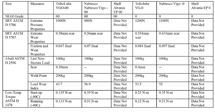
Table 3. Product Comparisons Table 3 was compiled by Michael D. Holloway
Next-Generation Tests
A screening test has recently been developed for targeted in-service robot grease analysis. A grease sampling device, the Grease Thief®, can be used to collect a sample and quantify the ferrous debris content (wear particles) and the optical characteristics (color) of the grease.
As a robot first begins to experience the effects of aging and hard use, its joints become ‘arthritic’. Yes, even an aging robotic workforce begins to show the signs of tiny wear particles of bearing and gear material. With these screening tests, a large fleet of robots and their joints can be assessed, and those at greater risk for breakdown or malfunction can be identified.
Another test, grease colorimetry, monitors the health of the grease as it ages and assesses the need for replacement and replenishment. The measurement of optical properties also allows the early detection of mixing of greases, e.g., due to the use of an incorrect product, and the degradation of seals, motors, and other components within the gearbox housing.
Together, these tests allow operators to care for their fleet of robotic workers and find those in need of proactive care before they (the robots) decide on their own to take a break at the most inopportune time.
Costs of operating and maintaining such advanced robots are not trivial. The grease alone can cost hundreds of dollars for a single robot replenishment. The downtime to perform the flushing, purging and restoration of the robot can be a significant drain on manpower and uptime. A typical grease change-out consists of the following steps:
• Lock-out/tag-out the robot • Pump an entire container of grease to flush the housing • Operate the robot with the plugs removed to purge excess grease • Clean purged grease from the outside of the robot, the floor, and the surrounding equipment • Replace the drain plugs • Reprogram, test, and return the robot to service
This entire operation can take over an hour, which means potential downtime and significant maintenance resources.
In contrast, with a Grease Thief® or a syringe, the steps are: • Tag-out the robot • Remove a drain or access fitting • Use the Greases Thief or syringe to extract a sample • Replace the fitting.
The robot is restored to service in minutes, and the sample can be locally screened or sent to a lab for analysis.
Wear Particles
In the past, ferrous debris monitoring was used to quantify the ferrous content of used grease samples. This provided an understanding of wear debris and was used as a primary indicator of wear levels. Ferrous debris instruments use an electromagnetic coil to measure iron content. A sensor detects the ferrous debris distributed throughout the entire sample as it is dropped into the instrument. This helps avoid inaccurate results due to making aliquots from the sample and instrumental particle size limitations, which are the two major issues that can arise when using other methods to track wear levels. Results are reported in parts per million (ppm).
A significant challenge with induction coil-type analyzers is the ability to present quantitative results that are independent of particle heterogeneity. This requires that the design allows the entire sample to be evaluated by means to an internal sample chamber inside the coil that measures energy across the sample. Devices that meet this requirement typically use a pair of precision round coils that generate magnetic fields. When a small amount of grease is inserted into one of the coils, ferromagnetic particles interact with the magnetic field and induce current frequency changes in the coils. The amount of change is proportional to the amount of ferrous particles, calibrated by weight in parts per million (ppm) with reference to an equivalent calibrated amount of iron. The sample vial is designed to optimize the position of the grease sample in the measurement coil. Before the measurement, the coils are automatically balanced electrically, removing the impact of temperature variation on the measurement. The result is a repeatable and stable measurement regardless of the operator and the environmental temperature, which is critical for a large service team doing on-site oil and grease analysis in the field.
Analytical Ferrography
Analytical Ferrography provides the most detailed analysis by microscopic examination of wear and particulate material in a sample. The method can detect the following: • Particle size and relative concentration • Metallurgy - ferrous and nonferrous
• Component source of wear • Wear mechanism (morphology) • Contaminant identification
Analytical ferrography is used extensively to predict failure modes and to justify equipment shutdown. A skilled analyst examines a prepared ferrogram slide with a computer-aided microscopic to identify the composition of the material present in a sample of used lubricant. Wear material and other debris suspended in a lubricant is deposited and separated onto a ferrogram slide for microscopic examination. Magnetic separation of wear material from the sample attracts ferrous particles out of the sample and onto the ferrogram slide. Although this method is most effective for ferrous material, it can capture and identify nonferrous wear particles and contaminants.
Consistency and Flowability
Die extrusion testing measures the consistency of a grease sample. This method can be used to compare consistency of a used sample to its baseline (unused grease) and generate a dimensionless index describing how the consistency of the grease has changed. Grease is extruded at various shear rates through a small die using the analyzer. As the grease is extruded, a force probe measures the force required to extrude the grease through the small die channel. Extrusion occurs at three speeds in order to create a consistency profile. This method allows grease consistency to be measured with only a gram of grease, significantly reducing the necessary sample volume for useful consistency testing.
Color
Grease colorimetry testing is used to validate changes in the observed appearance of greases related to darkening due to aging or overheating, color variations due to mixing products, and contaminants such as debris or other solids accumulating in the grease. A thin film of grease is loaded into an enclosed chamber and exposed to visible light (400-700 nm). The relative intensity of the light absorbed across the spectrum is measured, and source and spectral graphs are generated. This visible spectrum is characteristic of grease color and can be used to indicate grease color changes that are not quantifiable by the human eye.
Chemical Signatures
Fourier transform infrared spectroscopy (FTIR) is used to determine the chemical properties of organic compounds including greases. Oxidation products can be detected using this spectroscopic technique. Contamination, including mixing with incompatible greases, can be detected using this method. A small quantity of grease is subjected to infrared energy. Specific wavelengths of infrared energy excite the chemical bonds that make up the grease and generate a unique spectral fingerprint. This fingerprint can be compared to baseline data to determine chemical changes in grease composition, such as oxidation.
Summary
Several basic tests and advanced methods are used to evaluate the properties of in-service grease and determine the performance level of various greases. Care should be taken when selecting greases for robotics applications. Field data comparisons of various products can be quite valuable in such determinations.
Most robot operating manuals dictate that grease must be flushed and replaced annually or more often, but this may not always be necessary. It is important to give consideration to the operating
cycles, local temperatures (some robots are near furnaces, others in air-conditioned spaces), load, moment arm and acceleration (can cause wildly varying stresses on the gears and grease), and the ambient environment (dust, paint, chemicals, etc.) If Preventive Maintenance (PM) task frequency does not reflect changing variables, then it will inevitably be either overly conservative or ineffective. By adopting a Condition Based Maintenance (CBM) approach using grease sampling and analysis, the maintenance intervals can be optimized, and the maintenance resources for reliable robot operation can be used efficiently.
References
American Bearing Manufacturers Association (ABMA), Alexandria, VA, https://www.americanbearings.org/ American Roller Bearing Company, Bearing Lubrication, https://www.amroll.com/bearing-lubrication.html American Roller Bearing Company, Bearing Selection, Load and Life, https://www.amroll.com/bearing-selectionload-life.html
American Roller Bearing Company, Speed Limits, https://www.amroll.com/speed-limits.html 2002 Annual Book of ASTM Standards, Section 5, Petroleum Products, ASTM International, West Conshohocken, PA, https://www.astm.org/ Booser, E.R., Editor. Handbook of Lubrication. CRC Press, Inc. Vol 1,2, 1984.
Cash, Wes, Noria Corporation, How Rolling-Element Bearings Work, https://www.kaydonbearings.com/white_ papers_8.htm Emerson Bearings, Bearing Solutions for Your Robotics and Automation Applications, https://info.emersonbearing. com/lp-bearing-solutions-robotics-automation-applications?_ga=2.32114940.378166427.1615476366604188001.1615476366
Gunther, Raymond C., Lubrication, Chilton Book Company, New York, 1971. Grease Making Chemistry, Advanced Course Lubricating Grease Education Program, National Lubricating Grease Institute, A.P. (Tony) Wenzler, 1999. Holloway, Michael D. and Martinis, Max, A Primer on Greases Testing for Performance and Condition Monitoring, The NLGI Spokesman, Sept-Oct 2020, Volume 84, Number 4, pages 26 -39. Kowalik, G., Janosky, R., Advancements in Grease Sampling and Analysis Using Simple Screening Techniques, MRG Navigator, 2016. Lubricating Grease Guide, National Lubricating Grease Institute, Fourth Edition, Kansas City, Missouri, USA, 1996.
NLGI, NLGI Lubricating Grease Guide, Kansas City, MO Pirro, D. M. and A. A. Wessol, Lubrication Fundamentals, 2nd Edition, Marcel Decker, Inc. (New York, NY), 2001. SKF, Bearing Selection for Low-Speed Applications, https://www.kaydonbearings.com/white_papers_8.htm SKF, SKF Maintenance and Lubrication Products – Extending the Bearing Life Cycle, https://www.skf.com/binaries/ pub12/Images/0901d196800637eb-03000EN_tcm_12-163650.pdf#cid-163650 SKF, Selecting a Suitable Grease, https://www.skf.com/us/products/super-precision-bearings/principles/bearingselection-process/lubrication/suitable-grease Wurzbach, Richard, In-Service Grease Testing Techniques That Can Save Money and Time For Grease Manufacturers, The NLGI Spokesman, Nov-Dec 2018, Volume 82, Number 5, page 6 . Wurzbach, R., Williams, L., Doherty, W., Methods for Trending Wear Levels in Grease Lubricated Equipment, Society of Tribologists and lubrication Engineers (STLE) Annual Meeting, Las Vegas, NV, USA, May 2010.
Learn From Experts. Build Your Network. See the Possibilities.


Reliable Plant is Back in 2021

Reliable Plant is back in October 2021 with more unique opportunities to learn from world-class reliability leaders, lubrication experts and many other subject matter experts in the industry. For more than 20 years, the Reliable Plant Conference & Exhibition has been the only place where the optimal mix of technical excellence, cutting-edge technologies and proven solutions for the maintenance and reliability industry come together to share insights.
See the Possibilities
The true value of Reliable Plant is not only the world class learning, it’s the conversations that happen after class, around the lunch table or in the exhibit hall that can create that “light bulb moment.” When a mix of everyone from operators to upper-management attends Reliable Plant, new possibilities open up for reliability and maintenance teams. Ready for a more reliable plant? Join the reliability leaders gathering in Louisville, Kentucky on October 19 – 21 at Reliable Plant 2021.
About the Conference
Spanning four days, Reliable Plant 2021 includes workshops, learning sessions and case studies designed to upgrade the skills and knowledge of attendees. The conference will also feature approximately 130 exhibitors in a more than 200,000-square-foot exhibit hall inside the Kentucky International Convention Center. For more information visit Conference.ReliablePlant.com.


