
© 2024 Brno University of Technology – VUTIUM Press Editor © 2024 Belo Füri Text © 2024 Milan Kubín, Jiří Hirš Graphic design and layout © 2024 Karel Scherzer ISBN 978-80-214-6205-2 Contents About the Authors 7 Preface 9 Nomenclature 11 Experimental Setup 16 Chapter I. 21 Time course of fluid temperatures in wavy micro-channels Chapter II. 37 Surface tension in vertical wavy micro-channels Chapter III. 54 Surface tension in inclined wavy micro-channels Chapter IV. 75 Effect two-phase fluid flow in wavy micro-channels Chapter V. 94 Experimental investigation of effects heat transfer characteristic in wavy micro-channels Chapter VI. 127 Effect of heat flux, mass flux and quality vapour on the heat transfer coefficient in wavy micro-channels Chapter VII. 150 Effect of surface roughness in wavy micro-channels on critical heat flux and friction factor during condensation Chapter VIII. 176 Effect of position and connection heat exchanger on thermal and hydrodynamic behaviors in wavy micro-channels Chapter IX. 196 Investigation on the effect of gravitational orientation on fluid flow during condensation in wavy micro-channels Chapter X. 226 Prediction of the Nusselt number by heat transfer in wavy micro-channels Conclusion 258 Appendix 260 Subject index selected 296
f Liquid (Chapter 5, 6, 7, 9, 10).
film Liquid film between bubble and wall (Chapter 10).
G Gas (Chapter 2, 3); vapour (Chapter 4, 5) ; Gas phase (Chapter 4).
g Gas (Chapters 2, 3); vapour (Chapter 4, 5, 6, 7, 9, 10).
go Gas only, all flow taken as vapour (Chapter 10).
h Heat (Chapter 1); hot (Chapter 10).
chan Channel (Chapter 1).
IA Intermittent to annular flow transition (Chapter 10).
i Internal (Chapter 5, 7, 9, 10).
in, i Inlet (Chapter 1, 2, 3, 4, 5, 6, 8, 9, 10).
L Liquid (Chapter 2, 3, 5); liquid phase (Chapter 4).
l Liquid (Chapter 2, 3, 4, 5, 7, 9, 10).
LM Logarithmic mean (Chapter 1).
lam Laminar flow (Chapter 10).
lo Liquid only, all flow taken as liquid (Chapter 10).
M Mixture (Chapter 4).
m Determining (Chapter 4).
min Minimum value (Chapter 5, 7, 9, 10).
MT Mean temperature (Chapter 1).
nb Nucleate boiling (Chapter 10).
o, out Outlet (Chapters 1, 2, 3, 4, 5, 6, 8, 9, 10).
Ph Phase (Chapter 4)
pre Predicted (Chapter 5, 6, 10).
r Reduced (Chapter 5).
S Superficial (Chapter 4).
s Vapour (Chapter 9).
s Straight channel/vertical (Chapter 8, 10).
sat Saturation (Chapter 5, 10).
sp Single-phase (Chapter 10).
tp Two-phase (Chapter 10).
tt Turbulent liquid/turbulent gas (Chapter 10).
trans Laminar-turbulent transition (Chapter 10).
v Vapour phase (Chapter 2, 3); vapour (Chapter 4, 5, 7, 9, 10); viscous (Chapter 10).
W, w Water, wall, heated surface, properties evaluated at wall conditions, (Chapter 1, 2, 3, 5, 6, 10).
w Wavy channel/inclined, wall (Chapter 8, 10).
15
Experimental Setup
For investigating parameters affecting the effects of heat transfer and fluid flow, an experimental measuring line was set up to model the operating conditions during the condensation of water vapour in the tube bundle of a heat exchanger with wavy micro-channels. For the experimental investigation of the effects required parameters, the ideological design of the measuring line was initially performed, the main evaluated element, of which, was the tube heat exchanger with wavy micro-channels. The actual measuring line was set up on the basis of agreed design and technical documentation in the operating premises of the steam source and cooling water suppliers. The experimental setup for the description is divided into a water vapour circuit and cooling water circuit, see Figure 1. The water vapour circuit consists of a tank/source (A) where vapour is produced with a known temperature tv,in (°C) and pressure pv,in (Pa). The water vapour enters to the measured bundle of 55 copper thin-walled tubes (B), where it becomes to the condensation process. The condensate volume flow Vc (m3/s) and of condensate temperature tc,out (°C) is measured on the outlet of the tube bundle wavy micro-channels before flowing into the tank (C). The internal distance between tubes in the bundle is cooled by a circuit from a source of cold water (D). Volume changes of the cooling water are compensated by the expansion tank (E). On the vapour condensate at level H(m) of standard a bundle of wavy micro-channels is shown the outer gauge on level (G). The tube casing of the exchanger is insulated by thermal insulation with a thickness of 10 cm, so the heat transfer is not affected and it doesn’t lead to heat loss. The inner surface of the measuring wavy micro-channels is cleaned with a high percentage of alcohol cleaner and the purity of the water vapour from the steam generator is over 99.9 %. The object of experimental monitoring of the tube vapour/water heat exchanger was measured in a vertical position in combination with counterflow and parallel flow connection of cooling water. Besides that, changing the method of connection of the exchanger as counterflow/parallel flow parametric changes of input liquid were exercised, i. e. on the side of input vapour and on the side of input cooling water. The side of vapour: One variable parameter on the water vapour side was in the form of a change of the pressure of the saturated water vapour at the inlet of the exchanger and there is a synergistically associated change in the mass flow of water vapour in the exchanger. The range of pressure change was from 0.10 barg (heat water approx. 100 °C) to 3.20 barg (saturated vapour approx. 138 °C). The pressure of inlet saturated vapour was measured by temperature, independently on two places with the sensitivity of the thermocouple ± 0.10 K.
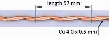
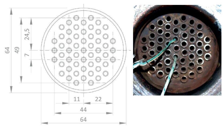
The side of water: The two variable parameters on the water side were temperature and water flow. The volume flow of water was measured independently of a water meter and a flow meter placed one behind the other. The devices work cumulatively, so the status and time were recorded in the form of a digital photograph containing the time (transfer to seconds) and status (transfer to liters). The temperature of inlet water was measured independently on two places with the sensitivity of the thermocouple ± 0.10 K, see Table 1.1 – 10.1, see Appendix. The measurement took place in a stationary form with a fixed geometry of the exchanger (position and connection) in combination with a fixed setting of input parameters (vapour pressure, temperature and water flow) and during the measurement was not actively interfered to the above setting. The thermal response of the heat exchanger vapour/water was recorded with pre-positioned thermocouples with sensitivity 0.10 K in a time step of 5 seconds, see Figure 3, 4. The hydraulic response of the heat exchanger was monitored independently by a water meter and a flow meter on the water side in the form of a digital photograph (status and time), as the record of the mass flow of water vapour condensate which was performed by photographing a digital scale (status and time), with sensitivity 0.10 g and a range from 0 to 30 kg. The evaluated element of the assembled measuring line is the experimental inclined tube heat exchanger with wavy micro-channels, a total of 55 pieces of copper thin-walled wavy micro-channels of the length 1300, 3.0 inner diameter and 0.5 mm wall thickness see Figure 2, Table 2. The adaptation of wavy walls have been applied commercially since the 1980s on vehicles and transpiration re-entry cooling of rocket boosters, ablative surfaces cross-hatching and combustion chambers for film vaporization. A wavy design can induce Dean’s vortices and an alternating secondary branch which helps in fluid mixing inside the channel where Dean’s vortices occurs when the flow in the wavy channel is very high and the flow is unstable and secondary flows are developed which introduce pairs of streamwise-oriented vortices. Phase changes in wavy micro-channels currently are part of a little-explored field of thermodynamics. Channels are intentionally cast in a bundle of 55 pieces and thus, some small geometric imperfections of each channel are eliminated. The currently measured values in data files correspond more to the statistical average and the edge effect is also eliminated. The bundle is surrounded by an outer copper tube with a diameter of 64 mm. The number of measured data points in a time step of 5 seconds, for a vertical position of the heat exchanger is, in total 29 264 i.e. 40.65 hours (counterflow connection 12 491 points, i.e. 17.35 hours, parallel flow connection 16 773 points i.e. 23.30 hours). For the inclined position of the exchanger 45 % the total number of data points is 35 124 i.e. 48.78 hours (counterflow connection 16 857 points, i.e. 23.41 hours, parallel flow connection 18 267 points, i.e. 25.37 hours). For the purpose of evaluating the recorded data for displaying the time course of the temperature of the liquids in the heat exchanger as the basic characteristics for determining heat transfer and other parameters an interactive electronic 3D graphic tool INSION – UTZB was created for recorded values on the primer and the secondary of the heat exchanger, both for parallel flow and counterflow. This interactive electronic 3D graphical tool is the subject of patent protection of the authors of this article. The time course of temperatures of condensing water in wavy micro-channels is the
16
17
essential starting point for the calculation of basic parameters according to suitable correlations and selected empirical relations of water for variants counterflow and parallel flow of the vertical heat exchanger and their evaluation.
A circuit wavy micro-channel is defined by its wavelength (λ), amplitude (A), hydraulic diameter (Dh), wall thickness (t), wavy ratio Y = λ /Dh, function y1 (x) = A cos (2 π x/λ), y2 (x) = A sin (2 π x/λ) for x = ˂ 0, t ˃
A parameter, ����, whose absolute value is equal to the ratio of the upper wall wave amplitude to the lower wall amplitude, is used to describe the configuration of the channels. We indicate both plus and minus values for ���� in order to distinguish the difference between the channels that have a same wave amplitude at the upper walls. When ���� < 0, the troughs of the lower wall and the crests of the upper wall face each other without phase difference. Whereas, for ���� < 0, the flow enters at x = x0 into an expanded part of the wavy channel and if ���� > 0 at the entrance of the wavy channel it involves into a contracted region in the vicinity of the upper wall. Besides that, for ���� = 0 the upper wall is straight and for ���� = 1 the channel is so called serpentine and for ���� = – 1 it is a raccoon channel.
Another characteristic of the wavy channels is the critical Reynolds number to transition from laminar flow to turbulence. In the wavy-walled channel, the critical Reynolds number depends on 2a/λ and is less than the critical Reynolds number (Rec = 2 300) for straight channels (W. M. Keys et al. 1980). Tolentino et al. (2008) have shown that the critical Reynolds number is even less than 250 for 2a/ λ = 0.18.
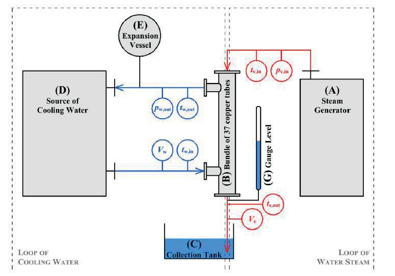
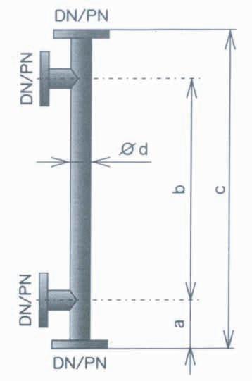
Figure 2 The experimental channel heat exchanger with wavy micro-channels
Figure 3 Schematic of the location of the sensors on the heat exchanger for reading the measured data, vertical position
Figure 4 Schematic of the location of the sensors on the heat exchanger for reading the measured data, inclined position
Figure 5 Wavy micro-channels heat exchanger
18
19 0,0 °C 0,0 °C 0,0 °C 0,0 °C 0,0 °C 0,0 °C 0,0 °C 0,0 °C 0,0 °C 0,0 °C 0,0 °C 0,0 °C 0,0 °C 0,0 °C 0,0 °C 0,0 °C 0,0 °C 0,0 °C 0,0 °C 0,0 °C 0,0 °C 0,0 °C 0,0 °C 0,0 °C 0,0 °C 0,0 °C
Figure 1 Schematic of the experimental set up
0,0 °C 0,0 °C 0,0 °C 0,00 kW (0,00 °C) 0,0 °C 0,0 °C 0,0 °C 0,0 °C 0,0 °C 0,0 °C 0,0 °C 0,0 °C 0,0 °C 0,0 °C 0,0 °C 0,0 °C 0,0 °C 0,0 °C 0,0 °C 0,0 °C 0,0 °C 0,0 °C 0,0 °C 0,0 °C 0,0 °C 0,0 °C 0,0 °C 0,0 °C 0,0 °C 0,0 °C 0,0 °C 0,0 °C 0,0 °C 0,0 °C 0,0 °C 0,0 °C
Chapter I. Time course of fluid temperatures in wavy micro-channels
1. Introduction
The time courses of fluid temperatures in energy equipment (of which heat exchangers of all qualifications are the necessary part) have been and are the subject of heat transfer work by many authors, for example [1], [2], [3], [4], [5], [6] [7]. The investigation of the course of temperatures of various fluids with a suitable flow arrangement of fluid in energy equipments and determining their optimal efficiency of transmission and operation characteristics can be found, for example [8], [9], [10], [11], [12], [13], [14], [15]. The special emphasis is placed on the fluid used and its physical and chemical properties. Not all of the fluids used in technical practice are suitable for their use in energy equipment and heat exchangers. Heat exchangers play a vital role in aerospace, automotive, medical, cryogenic, etc. engineering applications and processes such as refrigeration, chemical and oil refining, electric power generation and food processing, etc. In this article we will deal in more detail with the evaluation of the time course of fluid temperatures and selected temperature influences the parameters in wavy micro-channels of the heat exchanger in the vertical position and in the inclined position 45° in the view of the horizontal plane during the water condensation on the basis on the experimental investigation. As the base fluid for the examination water was chosen [16], [17] because of its being a quality, safe and non-flammable liquid with very good thermal properties. In addition water still finds its application not only as a refrigerant or temperature medium in technological processes and heating systems, cooling or air conditioning systems, but also in electrical engineering, the car industry, the pharmaceutical industry, etc. The contribution does not deal with the evaluation of the time course of temperatures of other types of waters (heavy water D2O etc.) or water with different impurities in the heat exchanger.
For the purpose of evaluating the recorded data set for displaying of the time course of temperature of the fluids in the wavy micro-channels of the exchanger, the interactive electronic 3D graphic tool INSION – UTZB was created for recorded values on the primer and the secondary for vertical and inclined heat exchanger position (parallel flow, counterflow). The technology uses MySQL database, application logic on PHP7 and rendering to HTML5 with CSS3 and JS. An intuitive value selector is available that allows definitions of the required data from the database of approximately 1.600.000 records. In the interactive tool one can directly choose the required type of recorded values, time frame, range of sensors by defining intervals or specifically individually, rate of ignoring deviations and the way of presented display on 3D chart (for days, sensors, daily averages,
20 The total length channel 1 300 mm The medium length of the channel in contact with water 1 142 mm The corrugated length of the channel 800 mm The uncorrugated length of the channel 171+171 mm The number of waves on one channel 28 External Internal The wave area of one channel 414,5 310,9 mm2 The area of the corrugated part of the channel 11 606 8 705 mm2 The area of the uncorrugated part of the channel 4 298 3 223 mm2 The total area of the channel 15 904 11 928 mm2 The area of 55 pcs channels 874 703 656 028 mm2
Table 2 The basic technical data wavy micro-channels of the heat exchanger
21
Figure 5 Cross section of heat exchanger with wavy micro-channels (dimension mm)
averages per sensors, details). The rendered 3D chart is fully interactive, it is possible to rotate, zoom in, omit graphic lines and take pictures into PNG or curve SVG format. Portability is also considered, so any given view, angle rendering, etc. is possible to be shared easily – by sending a link. The measuring line was based on the agreed technical documentation in the operating premises of the vapour and the cooling water supplier.
Figure 1.3.
The time courses of fluid temperatures in the heat exchanger with wavy microchannels, inclined position, counterflow
Figure 1.4.
The time courses of fluid temperatures in the heat exchanger with wavy micro-channels, inclined position, parallel flow
22
140,000 Temperarure [°C] Length [mm] 120,000 100,000 80,000 60,000 40,000 20,000 0,000 1400 1200 1000 800 600 400 200 118,1 100,3 100,0 73,6 40,0 38,0 28,4 21,6 11,8 75,8 61,8 0 140,000 Temperarure [°C] Length [mm] 120,000 100,000 80,000 60,000 40,000 20,000 0,000 1400 1200 1000 800 600 400 200 111,5 95,4 95,0 94,0 74,1 24,0 17,6 12,4 32,6 25,4 36,6 39,8 66,3 48,3 43,9 0
flow
Figure 1.2.
The time courses of fluid temperatures in the heat exchanger with wavy micro-channels, vertical position, parallel
Figure 1.1.
23 thick red line – modular curve of theoretical time course of temperatures (MCTTCT – vapour, condensate thin red line – experimental time course of temperature (ETCT) – vapour, condensate thick line – modular curve of theoretical time course of temperatures (MCTTCT) - cooling water thin line – experimental time course of temperature (ETCT) – cooling water 37,7 80 Temperarure [°C] Length [mm] 70 60 50 40 30 20 10 0 1400 1200 1000 800 600 400 200 71,2 61,1 40,5 59,1 40,2 38,0 35,2 33,6 32,8 40,8 40,8 0 120 Temperarure [°C] Length [mm] 100 80 60 40 20 0 1400 1200 1000 800 600 400 200 112,6 101,6 96,6 98,3 97,3 46,8 42,8 34,2 21,6 14,2 25,0 91,2 68,6 66,1 82,0 0
The time courses of fluid temperatures in the heat exchanger with wavy micro-channels, vertical position, counterflow
Table 1.1.
The measured data in the selected time frame of the heat exchanger measurement with wavy micro-channels for the vertical position a) counterflow, b) parallel flow and for the inclined position c) counterflow, d) parallel flow, see Appendix
2. Solution methods
For many fluids, specific temperature profiles in energy equipment, including the heat exchangers in various positions (vertical, horizontal, inclined) are given in contributions, reviews and professional books, for example [19], [20], [21], [22], [23], [24] [25]. All the time courses of temperatures should be carefully checked before use because very often accuracy between different sources is not guaranteed. This paper compares the time courses of temperatures and selected temperature parameters in the condensation of water vapour in the heat exchanger in the vertical and inclined wavy micro-channels. The evaluation fluid is water, the inlet and outlet temperatures of the primer and the secondary are obtained from the interactive electronic 3D graphic tool INSION - UTZB, see Table 1.2.
Table 1.2.
The inlet and outlet temperatures of fluids for different positions of the heat exchanger with wavy micro-channels
2.1.
Parameters influencing the time course of temperatures
1. Heat Transfer Fluids (HTFs)
HTFs can be classified by their states of matter during normal operating conditions. Additionally to the three standard states (gaseous, liquid, solid), HTFs that undergo a phase change and supercritical fluids are also possible. Important thermo-physical properties of HTFs are low temperature limitation (solidification temperature), high upper temperature limitation (evaporation temperature/thermal stability limit) at low pressures, high thermal conductivity → receiver temperature close to HTF temperature, low viscosity → lower pumping power requirements, high density and heat capacity → enable use as storage medium, possibility of usage as working fluid, chemical compatibility (low corrosivity) with contact materials, low cost, high availability, low toxicity, flammability, explosivity and environmental hazard. [26]
24
Position HE vertical inclined counterflow parallel flow counterflow parallel flow inlet temperature (°C) hot fluid Ti 118.1 111.5 112.6 71.2 cold fluid ti 11.8 12.4 14.2 32.8 outlet temperature (°C) hot fluid To 75.8 66.3 21.6 40.8 cold fluid to 61.8 48.3 68.6 37.7