
LED Linear Ligh�ng System

35W / 40W / 45W / 50W / 55W / 60W / 65W / 70W optional
DALI / DIM switch/ 1-10V dimmable optional
Sharp / narrow / wide / flood / flat / asymmetric / double asymmetric
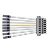
5 / 8 / 12 wires trunking rail
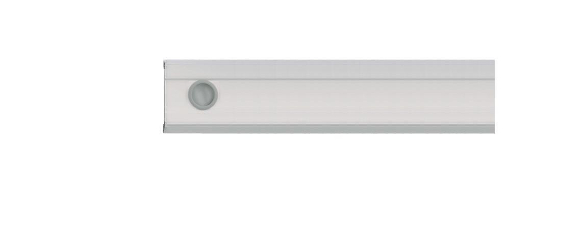
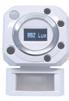
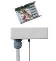
Daylight sensor, motion sensor
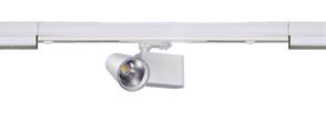
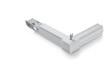
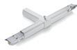
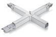
L , T , X node connector
160LM / 180LM per watt
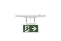
DC emergency / central safety emergency supply / built-in battery supply
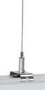
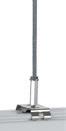
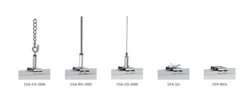
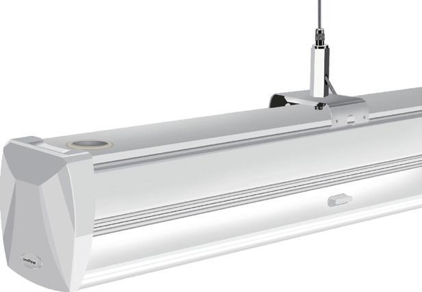
Cord / chain / rod / surface mounted / mounting clip
2700K / 3000K / 3500K / 4000K / 5000K / 5700K / 6500K
600mm / 1200mm / 1500mm / 2400mm / 3000mm / 4500mm

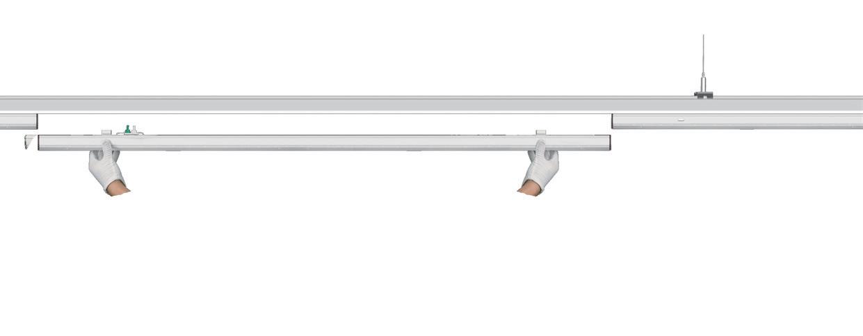
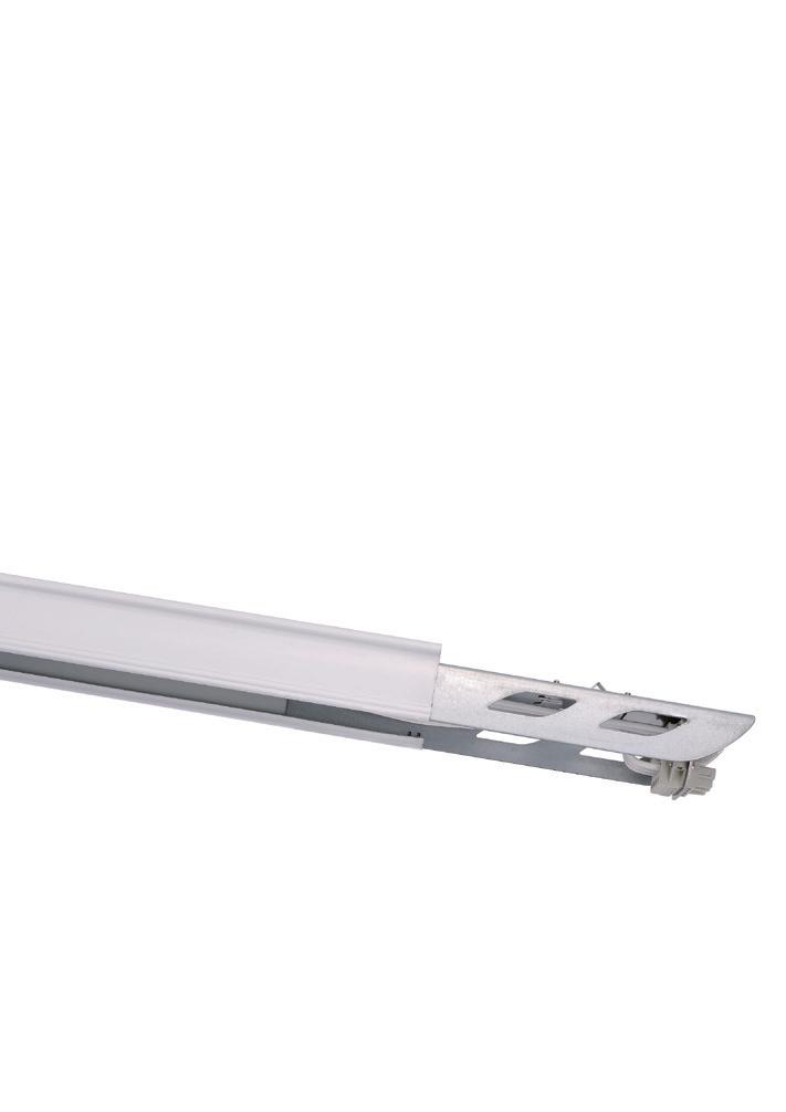
·3-phase pre-selection via moving luminaire male connector pin to right or left to install in the rail
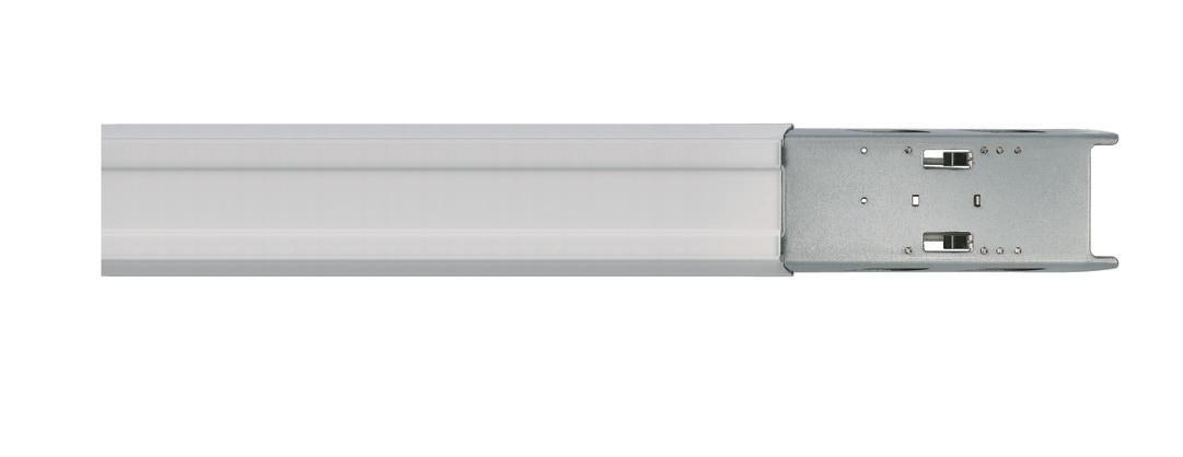
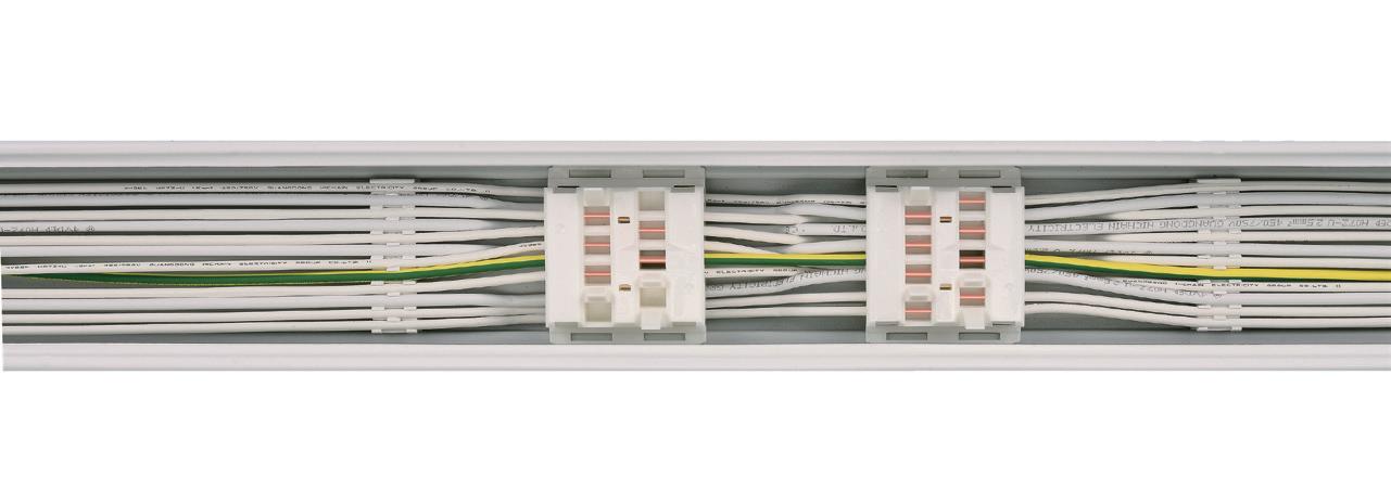
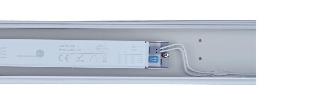
·Trunking rail as standard with 5, 8 or 12-core through-wiring with 2.5mm²cable for power supply and 1.5mm² cable for dimming control.
·The maximum current is 16A, allowing 70pcs of 1500mm 50W in one serial row with 220VAC power supply
·Separate power supplies, dimming or emergency supply can be integrated
·Electrical feed possible in sideward or end area of a trunking rail arrangement via special trunking rail element
·Trunking rail modules with pre-assembled connectors
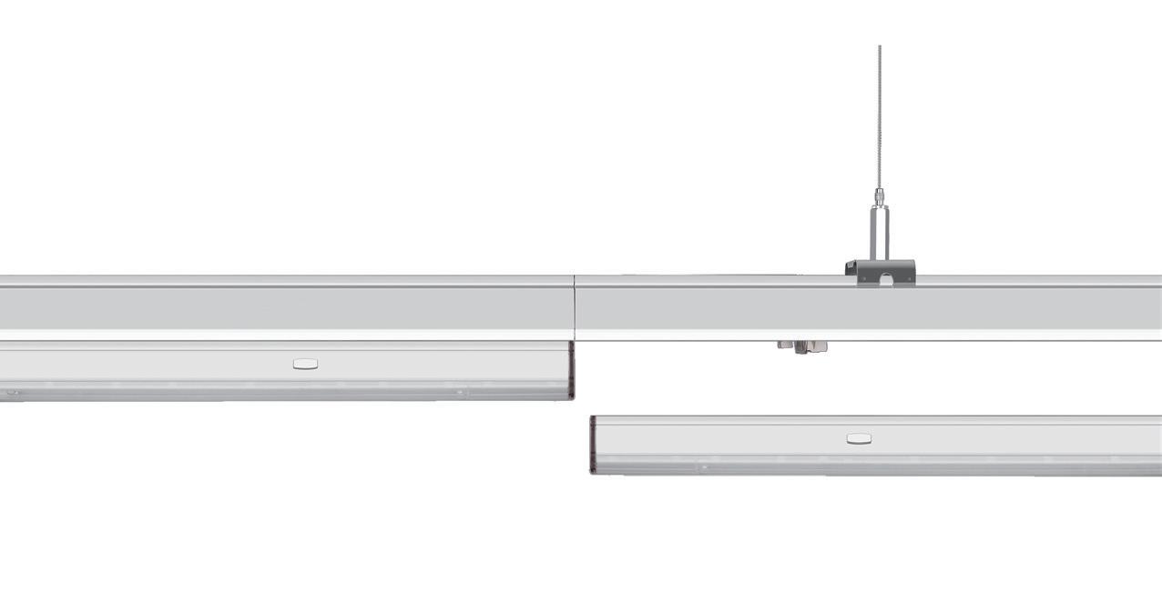
·Wide distances between suspension points to 3m with self-supporting connector elements
·Simple mounting of trunking rail elements with pre-assembled connectors with integral plug-in system (electrical and mechanical connection)
·Flexible electrical feed-in and feed-out points
5-core trunking rail :
8-core trunking rail :
12-core trunking rail :
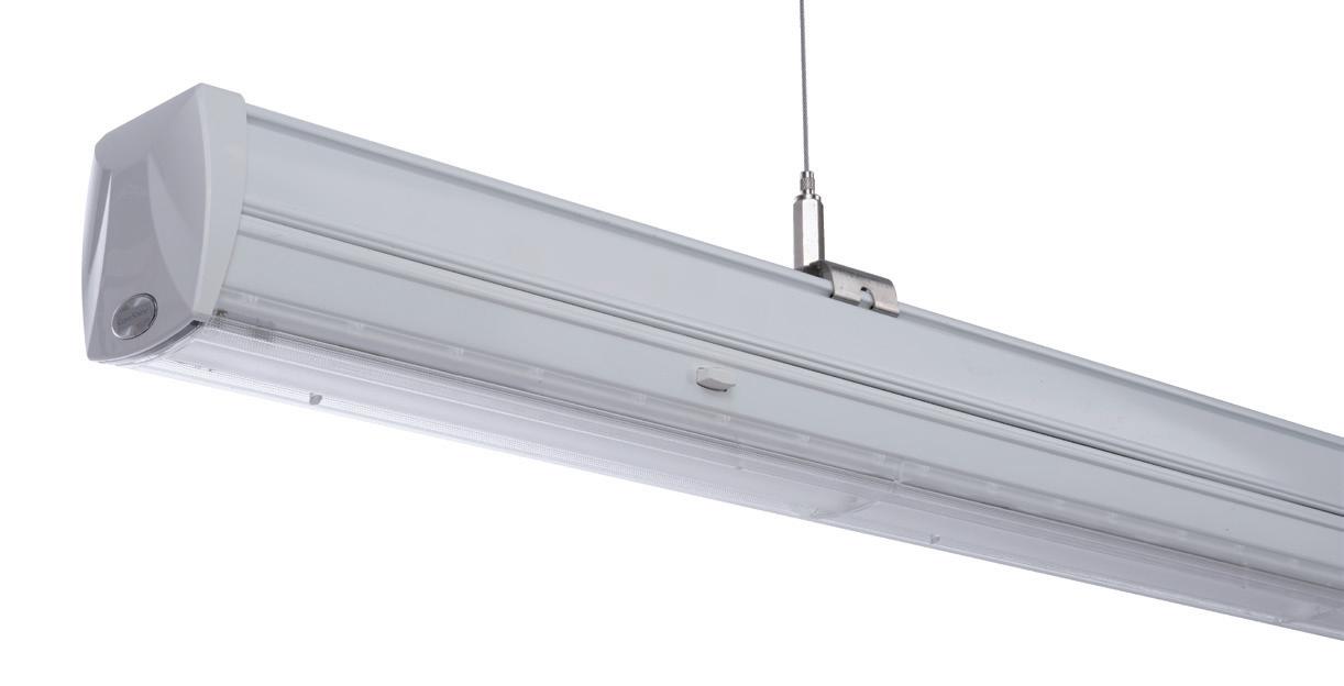
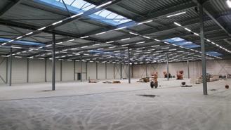
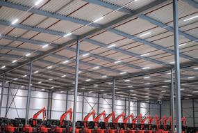
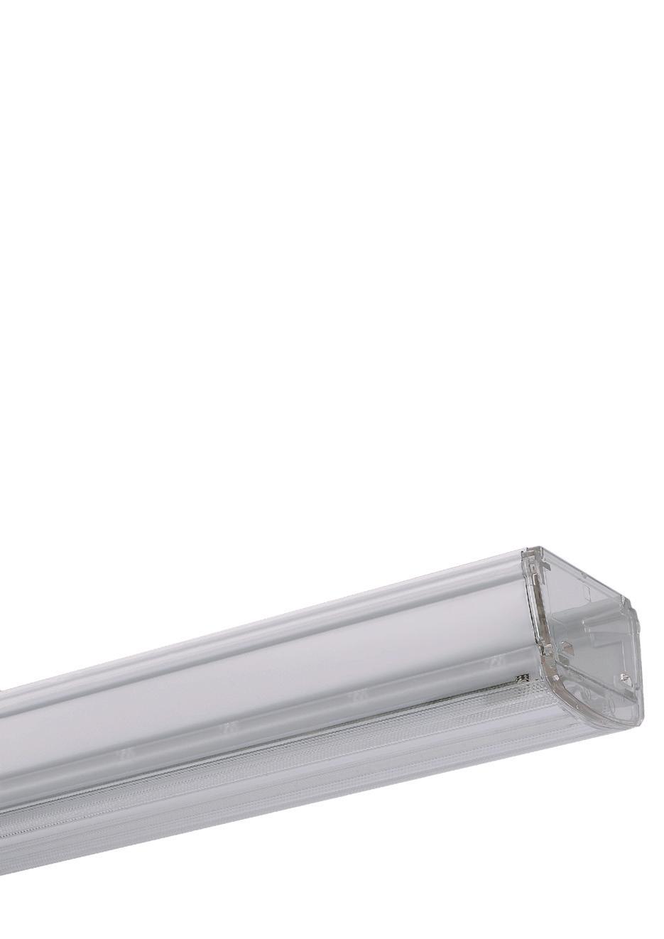
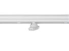
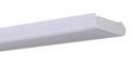
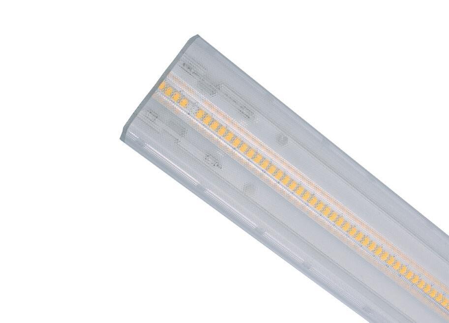
A continuous-row LED lighting system could be created only by a trunking unit and a LED luminaire. It appears as a consistent continuous-row system, without any visual interruption or different reflectors. The luminaire and trunking rail are perfectly matched to each other.
All drivers are DIP Switch Driver. Power can be selectable by setting the buttons in different position, which is more convenient for customers to make inventory.
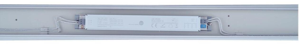 DIP Switch Driver
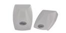
White
RAL 9016
Black
RAL 9017
DIP Switch Driver
White
RAL 9016
Black
RAL 9017
FD-120° Extremely wide
wide
NR-60° narrow SP-30° extremely narrow
External emergency with Constant current(On/off) LED driver
Luminaires with Constant current(on/off) led driver connect to the central backup battery or UPS through EL, EN. When no power is detected, the luminaires are off; when power is detected, the luminaires
are 100% brightness.
External emergency with DALI driver
Luminaires with DALI driver connect to the mains electricity, central backup battery or UPS. When no power is detected, the luminaires are off; when AC power is detected, the luminaires are on 100%; when DC power is detected, the luminaires are on 15%.
Internal emergency with built-in battery pack
Different combination of emergency driver and battery pack are available. When CHR detects that there is power, luminaires are on 100%; when no power detected, luminaires will work according to the selected emergency driver. Different emergency drivers and battery packs can be freely combined as below.
ACCESSORIES
Code Definition
CFT = Steel trunking rail
Length:
06 = 600mm
09 = 900mm
12= 1200mm
15 = 1500mm
24 = 2400mm
30 = 3000mm
36= 3600mm
45 = 4500mm
Option:
N = normal rail
F = feed-in rail
T = terminal rail
Wire quantity:
05 = 5 wires
08 = 8 wires
12 = 12 wires
Color:
WH = white
BK = black
SV = silver e.g.: CFT-15F-05WH 1.5m linear trunking rail, feed-in, 5 wires, white color

Category
Code Definition
CFL = Steel luminaire
Length:
12 = 1200mm
15 = 1500mm
24 = 2400mm
30 = 3000mm
Power:
30, 40, 60 = 30W, 40W, 60W
35, 50, 70 = 35W, 50W, 70W
CCT:
27 = 2700K
30 = 3000K
35 = 3500K
40 = 4000K
50 = 5000K
57 = 5700K
65 = 6500K
e.g.: CFL-1550-40NR-08WH-DA
1.5m linear luminaire, 50W, 4000K, narrow angle, 8 wires, white color, DALI dimming.
Beam angle
SP = sharp
NR = narrow
WD = wide
FD = flood
DS = double asymmetric
RS / LS = right / left asymmetric
FF / FT = flat frosted / transparent
Wire quantity:
05 = 5 wires,
08 = 8 wires, 12 = 12 wires
Color of the housing:
WH = white shell
BK = black shell
SV = silver shell
Function:
E1 = 6W emergency power supply
E2 =12W emergency power supply
B1 = 1800mAh emergency battery pack
B2 = 3600mAh emergency battery pack
DA = DALI dimming
10 = 1-10V dimming
Order Number List - Node Connector - Feed-in Box
Category
CFNModel Color X WH BK Wire Quantity X 05 08 BF 12 SV

e.g.: CFN-BF-05WH Feed-in box, 5 wires, white color
Order Number List - L, T, X Node Connector
Category
CFN -
Code Definition
CFN= Steel node connector
Model: BF= Feed-in box
Wire quantity:
05= 5 wires
08= 8 wires
12= 12 wires
Color:
WH= white
BK= black
SV= silver
Option:
OI=feed-in by the left side; feed-out by right side
IO=feed-in by the right side; feed-out by left side
OIO=one side for feed-in; two sides for feed-out
IOOO=one side for feed-in; three sides for feed-out
e.g.: CFN-LOI-05WH
L-node connector, feed in by the left side and feed out by right side, 5 wires, white color L Node Connector T Node Connector X Node Connector
Luminaire Characteristics / Standard Version / 35W/50W/70W
Product Description
Tool free installation
Continuous line
Plug and play
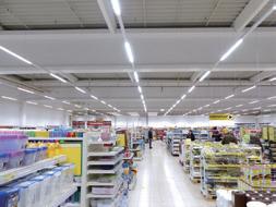
Application
Commercial Industrial Warehouse
Model No.
Outer dimensions
Input power
Dip switch to
Input voltage
Input current
Mains frequency
PF (at 230 V, 50 Hz, full load)
Lumen
Efficiency
CCT
CRI
R9 SDCM TSL-1535
Beam Angle
Dimming
Dimming range
Flicker percent
Flicker metric Pst LM
Stroboscopic effect metric SVM
Type of protection
Operating humidity
Storage humidity
Ambient temperature Ta (at life-time 50,000 h)
Warranty
Storage temperature Ts
1500*76*70mm
35W
35/40/45/50W
220 - 240VAC
0.2A max
50/60HZ
0.9
5600lm/6300lm
50W
35/40/45/50W
220 - 240VAC
0.3A max
50/60HZ
0.9
8000lm/9000lm
160lm/W / 180lm/W 160lm/W / 180lm/W
2700-6500K
80Ra
>0
<3
30°, 60°, 90°, 120°
LS/RS, DS, FF NO
2700-6500K
80Ra
>0
<3
30°, 60°, 90°, 120° LS/RS, DS, FF
1500*76*70mm
70W
55/60/65/70W
220 - 240VAC
0.4A max
50/60HZ
0.9
11200lm/12600lm
160lm/W / 180lm/W
2700-6500K
80Ra
>0
<3
30°, 60°, 90°, 120° LS/RS, DS, FF NO / ≤5%
5 years
-40 - 85°C
Product Description
Tool free installation
Continuous line
Plug and play
Application
Commercial
Industrial
Warehouse
Model No.
Outer dimensions
Input power
Dip switch to
Input voltage
Input current
Mains frequency
PF (at 230 V, 50 Hz, full load)
Lumen
Efficiency
CCT
CRI
R9
SDCM
Dimming
Dimming range
Flicker percent
TSL-1535-DA
1500*76*70mm
35W
35/40/45/50W
220 - 240VAC
0.2A max
50/60HZ
0.9
5600lm/6300lm
160lm/W / 180lm/W
2700-6500K
80Ra
>0
<3
30°, 60°, 90°, 120°
TSL-1550-DA
1500*76*70mm
50W
35/40/45/50W
220 - 240VAC
0.3A max
50/60HZ
0.9
8000lm/9000lm
160lm/W / 180lm/W
2700-6500K
80Ra
>0
<3
TSL-1570-DA
1500*76*70mm
70W
55/60/65/70W
220 - 240VAC
0.4A max
50/60HZ
0.9
11200lm/12600lm
160lm/W / 180lm/W
2700-6500K
80Ra
>0
<3
LS/RS, DS, FF
DALI DT6/switch
1% - 100%
≤5%
Flicker metric Pst LM
Beam Angle ≤1.0
Stroboscopic effect metric SVM
Type of protection
Operating humidity
Storage humidity
Ambient temperature Ta (at life-time 50,000 h)
Warranty
Storage temperature Ts
30°, 60°, 90°, 120° LS/RS, DS, FF
DALI DT6/switch
1% - 100% ≤5%
≤1.0
≤0.4 IP20 10% - 80%
30°, 60°, 90°,120° LS/RS, DS, FF
DALI DT6/switch
1% - 100%
≤5%
≤1.0
≤0.4
IP20
10% - 80%
10% - 80%
-25 - 40°C
-25 - 40°C 10% - 80%
5 years -40 - 85°C
5 years -40 - 85°C
-25 - 40°C
5 years
-40 - 85°C
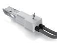
Product description
Constant current LED driver
Lifespan: 50,000h
5 years warranty
Properties
Over voltage protection with automatic restart
Overload protection
Short-circuit protection with automatic restart
Surge voltage: 2.5KV
Model No.
Input voltage
Input current
Mains frequency
PF (at 230 V, 50 Hz, full load)
THD (at 230 V, 50 Hz, full load)
Inrush current
Turn on time (output)
Output voltage
Output current
Max output power
Efficiency (at 230V,50Hz,full load)
Dimming
Dimming range
Output LF current ripple
Surge (between L – N)
Surge (between L/N – PE)
Type of protection
Operating humidity
Storage humidity
Ambient temperature Ta
(at life-time 50,000 h)
Max. Casing temperature Tc
Storage temperature Ts
TSL2U-50
220 - 240VAC
0.33A max
50/60HZ 0.9 15%
28A@110us ≤1s
55 - 82V
0.43/0.49/0.55/0.61A
50W
90% NO / ≤5%
2.5KV 2KV IP20 10% - 80%
TSL2U-70
220 - 240VAC
0.47A max
50/60HZ
0.9 15%
30A@110us ≤1s 55 - 82V
0.69/0.73/0.79/0.85A 70W 91% NO / ≤5% 2.5KV 2KV IP20 10% - 80%
80°C
-40 - 85°C
Outer dimensions 10% - 80% -25 - 60°C
280*30*22mm
10% - 80%
-25 - 60°C
80°C
-40 - 85°C
280*37*31mm
Over voltage protection with automatic restart
Short-circuit protection with automatic restart
Model No.
Input voltage
Input current
Mains frequency
PF (at 230 V, 50 Hz, full load)
THD (at 230 V, 50 Hz, full load)
Inrush current
Turn on time (output)
Standby power Psb
Output voltage
Output current
Max output power
Efficiency (at 230V,50Hz,full load)
Dimming
Dimming range
Output LF current ripple
Surge (between L – N)
Surge (between L/N – PE)
Type of protection
Operating humidity
Storage humidity
Ambient temperature Ta (at life-time 50,000 h)
Max. Casing temperature Tc
Storage temperature Ts
Outer dimensions
TSL2H-50-DT6
220 - 240V
0.3A max
0/50/60HZ
0.9 15%
25A@120us
≤1s
≤0.5W
30 - 40V
0.84/0.95/1.07/1.1
8A 47W
88%
DALI DT6/switch 1% - 100% ≤5% 2.5KV 2KV
10% - 80%
- 80%
-25 - 60°C
85°C
-40 - 85°C
280*32*30mm
TSL2H-70-DT6
220 - 240V
0.43A max
0/50/60HZ
0.9
15%
30A@110us
≤1s
≤0.5W
30 - 40V
1.3/1.42/1.53/1.65A
66W
88%
DALI DT6/switch
- 100%
- 80%
- 80%
-25 - 60°C
85°C
-40 - 85°C
360*32*30mm