TABLE OF CONTENT
ABOUT ME
My passion for architecture is manifested through the union of visual essentality and technical elaboraton. My rigorous and simple communicatve style blends in a easy way with complex and elaborate elements. Through the use of clean lines and geometric shapes, I create spaces that exude order and harmony. But it is in the atenton to detail that my passion is freed.
LEONARDO PELLI | CV
SEP 2018 - AUG 2022
PERSONAL INFORMATION
88 Chapter Road, London NW2 5LP +44 7825 958014
leonardopelli@icloud.com
EDUCATION
UNIVERSITY OF WESTMINSTER, LONDON, UK
BA (HONS) ARCHITECTURE (RIBA PART 1)
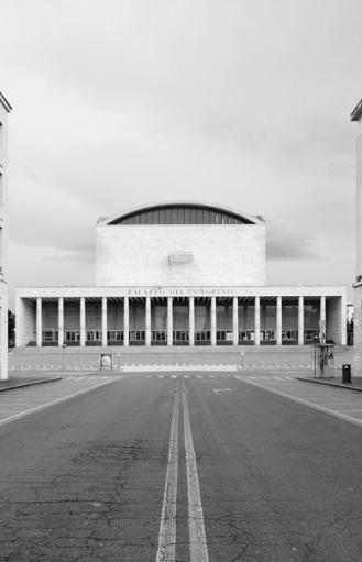
Dissertation: Light and space, shadow and void: fascist architecture in Italy today, a study of the Palazzo dei Congressi at EUR.
Year 3: DS3.4, Paolo Zaide + Tom Budd. Project: Gravesend; The interrupted link.
Year 2: DS2.2, Natalie Newey + Richa Mukhia. Projects: Albert Island; Observatory on the Thames.
Year 1: DS1.B, Richard Watson + Emma Perkins. Projects: London; Hepworth’s Studio and Flat. GRADE 2:1
SUMMER 2021
AMERICAN UNIVERSITY OF ROME, ROME, IT ARTS OF ROME
Art of Rome is a course based on the history of art and history of Rome. The course hones a method of description, critical analysis andninterpretation of art and builds.
SEP 2012 - JUN 2017
I.I.S. CARAVAGGIO, ROME, IT ARCHITECTURE, DIPLOMA SCUOLA SECONDARIA SUPERIORE
Main subjects: Architecture, History of Art, Orthographic Drawing, Philosophy, Maths, Physics, chemistry, Italian and English.
WORK EXPERIENCE
JAN 2022 - MAR 2022
HYPHEN, LONDON, UK
UoW 3rd Year BA Architecture work experience
During the project of a store located in London for a well-known clothing brand, I collaborated on the site visits, interviews with the contractors and produced some project’s drawings.
JUL 2014- PRESENT
GRANDI IMPIANTI SRL, ROME, IT DESIGN ASSISTANT
Since my adolescence I have periodically worked as design assistant in this business based in Rome. The company deals with industrial kitchens, taking care of everything, from design to sales, from assembly to maintenance.
OTHER EXPERIENCE
JAN 2022
STROKE, DESIGN AND WELL-BEING WORKSHOP IMPERIAL COLLEGE, UOW
Collaborative design workshop with Imperial College medical students.
RIBA STUDENT MENTORING SCHEME
Jon Pyle Director/Architect at Resilient Edge Architecture Ltd
Attended several mentoring and formative sessions
SKILLS
DIGITAL SKILLS
Microsoft Office Suite: Proficient
Archicad: Proficient (8 year of experience)
Adobe Creative: Proficient (3 years of experience)
COMMUNICATION SKILLS
Italian: native speaker
English: fluent
Spanish: fluent
REFEREES
Paolo Zaide
Head of Architecture & Cities | UoW p.zaide@westminster.ac.uk
Wayne Taylor Director at Hyphen wtaylor@hyphen.archiLONDON NARROWBOAT CLUB
Albert Island, United Kingdom, 2021

In a future world where most of the transports will be electric, even vintage UK boats will be converted. Thanks to solar panels and batery motors, this shipyard will make the old diesel or gasoline boats fully electric. The community of narrowboats, connected by long English canals, will fnd hospitality in a modern clubhouse during the retroftng and updatng of the houseboat. — The site is located near London city airport on an island called Albert Island, currently devoid of habitaton and dominated by industrial buildings. At the basis of the defniton of the shape of the building, there was a careful analysis of the place and the functon.
The design draws inspiraton from the narrowboat shape and the need to accommodate several of them. Emphasizing solar and wind consideratons, the building takes advantage of solar light as much as possible. The upper foor, dedicated to sleeping quarters, faces the sunrise while being protected by adjustable louvres. The boatyard’s fat roof is covered by a garden, ensuring a pleasant indoor climate even during hot summers. The building’s southern area utlizes a Trombe wall to harness the sun’s energy, and the glass used throughout is photovoltaic, enabling the structure to generate green power.

The narrowboat is a partcular type of canal boat, built to ft the narrow locks of the UK. In the 18th century, the UK’s canal system provided a natonwide transport network fueling the Industrial Revoluton, where narrowboats played a key role. Wooden boats were initally drawn by a horse walking on the canal. Horses were gradually replaced with steam and then diesel engines. Today,
narrowboats are used for holidays, touring, or as permanent residences. Lately, the number of boats has been rising, with the number of licensed boats on canals and rivers estmated at 30,000 in 2014. The number of narrowboats will contnue to grow in the future, the community will become larger and diesel and gasoline engines will be replaced with electric motors.

This place is designed for all those who will need to retroft their boat and who will need accommodaton while their ‘home’ is uninhabitable, but it will also be a meetng point for the narrowboat community. The design of the building will host
the boats in progress on the water level while on the frst foor, the boat owners will fnd intmate accommodaton, in the same foor the community will reunite in a typical boat club-inspired space that includes a restaurant and bar.


The boats will dock on a pier placed in front of the structure that will host them during the stay of the owners. The boats that will need retroftng will then be moved by water within the boatyard which has a predefned route for them. The boats entering the structure will be lifed from the water by a crane that will insert
them into the circular path on the foatng platorm following the various retroftng steps. The upper foor remains independent from the workshop giving a common experience that provides all the comforts for those who spend a few days in the structure but also for those who are only there for a day in the community.
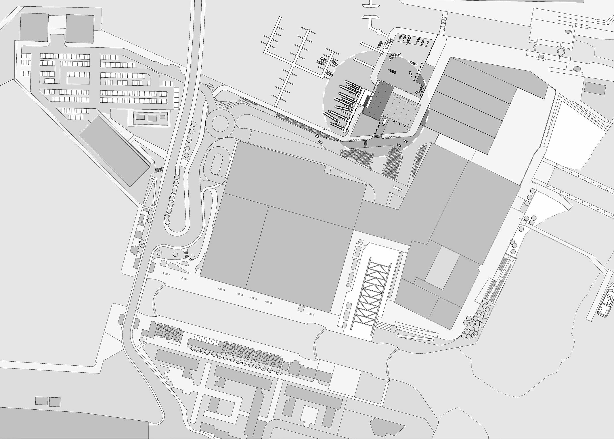


The boatyard has been designed to respond to the needs foreseen by the processing of boats and the spaces necessary to accommodate a certain number of them. Even the Club and the accommodaton located on the upper foor have
been designed to best respond to the community. Despite being on the same foor, the sleeping area is well-insulated and does not share any walls with the noisier parts of the foor, guaranteeing privacy and excellent sound insulaton.
The structure is formed by a metal skeleton that cover a pre-existng recess in the mainland. The metal structure extends over the water like a bridge that gives life to a new space by exploitng the underlying water and its span The design and structural choices were made trying to beneft the environment. Steel has been chosen also for its recyclable nature. Once the life of the
building is over, the steel components can be brought back to the foundry to take on any other functon.The structure also houses sustainable techniques and innovatons like the Trombe wall (a passive solar system that exploits solar energy for the internal air conditoning of buildings.), louvres panels, solar tubes, green roof, photovoltaic glass and dry technology and materials.
Metal sheet type “Future 555”
OSB panel covered with TNT
Waterproof case
Iecacem (c) classic for slopes
Rofx Polydros insulator
Celenit N insulaton Vapor barrier

Ieca (c) CLS 1800 Rck 45
Corrugated sheet
Metal fasscing
Retentol tee
Soil Flooring
Aktvfoor panel for heatng
Calpestop (c) super
Celenit N insulaton
Iecacem (c) classic for substrates
Ieca (c) CLS 1800 Rck 45
Corrugated sheet
Filter fabric
Resevoir layer

Moisture-retenton layer
Aeraton layer
XPS rigid insulaton
Drainage layer
Root barrier
Protecton course
Air, water, vapour barrier
Dry layering technology is as an efectve alternatve to traditonal wet or cementtous constructon systems. The use of a dry architectural envelope and load-bearing structure is at the base of a design that aims at energy and cost savings, allowing for a drastc reducton in the materials used, usually recyclable (e.g., load-bearing or secondary structures made from recycled aluminum). The dry layering system involves the integraton of

lightweight, thin, and high-performance elements with diverse mechanical and physical propertes, enabling signifcant energy savings and optmizing the assembly maintainability of the technological units. When composing the dry layering of an eco-sustainable constructon, choices are directed towards natural or recycled materials. Rockwool, fr, cork, wood, and cellular glass meet the requirements of an environmentally friendly constructon.


OBSERVATORY OF THE THEMES
Albert Island, United Kingdom, 2021
The Observatory on the Thames is located on Albert Island, a captvatng locaton in London, really close to the LDN City Airport. Currently characterized by warehouses and uncultvated areas, the island will soon undergo a comprehensive redevelopment. This project aims to return this piece of land to the citzens and communites that can beneft the most from it. With its distance from the bright lights of the city and tall buildings, the
site ofers an exceptonal opportunity for stargazing enthusiasts and the wild shore and the river that surrounds the island make it an ideal spot for birdwatching. The design focuses on the needs of both communites that share the necessity of a tall structure with expansive views. The challenge was to design an easily accessible tower that eliminates architectural barriers, ensuring seamless access for individuals with disabilites.

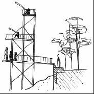
The sketches on the lef side illustrate in sequence the inital idea of optmizing views through a tall structure, the task of ensuring accessibility for all, and the proposed soluton of a single ramp providing easy access. The concept collage on the right page creatvely explores key design spaces and ideas using a combinaton


of images, drawings, and contrastng elements. It communicates the envisioned use of the structure and the potental experiences and actvites within it, including a stargazing platorm, a planetarium with astronomical and environmental projectons, a bird observaton platorm, and a ramp that ensures barrier-free access.


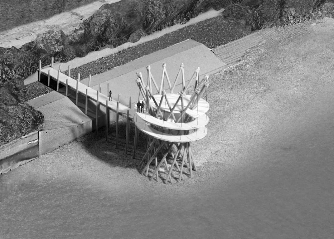
The inital 1:50 scale model of a room provided a valuable opportunity to assess the spatal layout, experiment with materials and structural elements. Most signifcantly, it allowed for the inclusion of a dome within the structure. The dome introduces new actvites for both starga-
zers and birdwatchers. Educatonal images will be projected onto the dome, aligning with celestal events and bird migraton paterns during specifc periods. This educatonal initatve not only imparts knowledge but also ofers enriching and enjoyable experiences for visitors.

The exploded view illustrates the fnal design of the observaton tower, highlightng its structural details and the actvites carried out inside. The structure of the tower, derived from a hyperboloid (a hyperboloid structure is a doubly ruled surface that can be built with straight beams, produ-
cing a strong structure at a lower cost than other methods), that makes it stable and very open, in fact, its geometric characteristcs guarantee stability against external forces through the structural nodes while its openings allow the passage of strong river currents and winds without obstructon.
1. Sidewalk with ramp. Slope 8%
2. Footbridge
3. Access to the structure
4. Planetary room
5. Ramp. Slope 8%. Access to upper foor
6. Standard fat restng area
1. Sidewalk with ramp. Slope 8%
2. Footbridge
3. Ramp. Slope 8%. Access to lower foors
4. Standard fat restng area
5. Main terrace
6. Wind rose. To guide visitors and quickly fnd the North Star, the only one to always maintain its positon
The main structure is made up of modular and prefabricated glulam beams that match perfectly together, held in place by a specially designed joint. The tower requires some steel cable wires to create a tensile structure capable to hold the ramp that surrounds it. The tower exhibits vibrant
colour contrasts, yet the dominant colours harmonize with nature, enhanced by the ivy that will grow around the wooden structure, giving it the appearance of a tree. The choice of materials and constructon techniques ensure easy maintenance and sustainability for long-lastng durability.





GRAVESEND STATIONSQUARE
Kent, United Kingdom, 2022
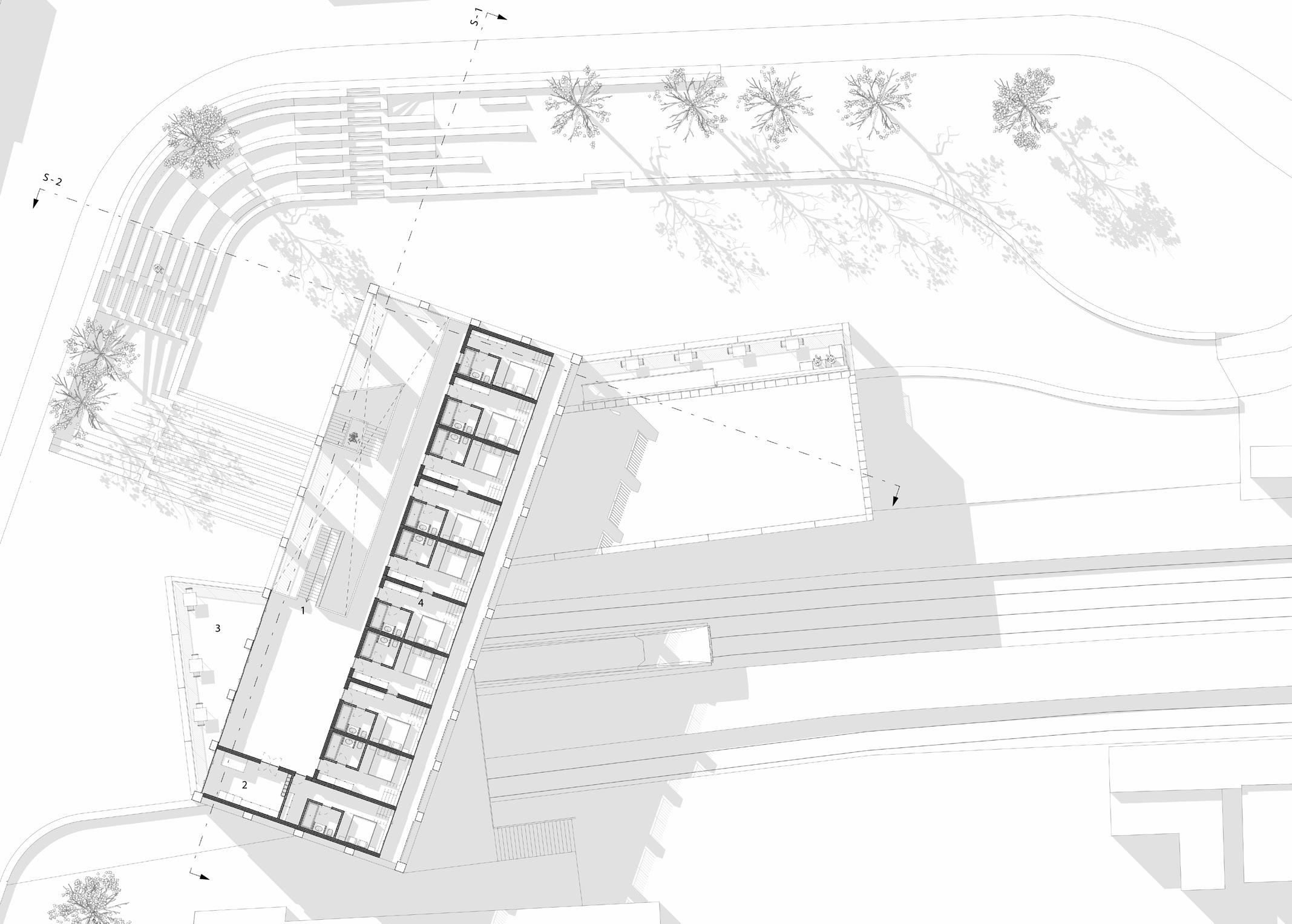
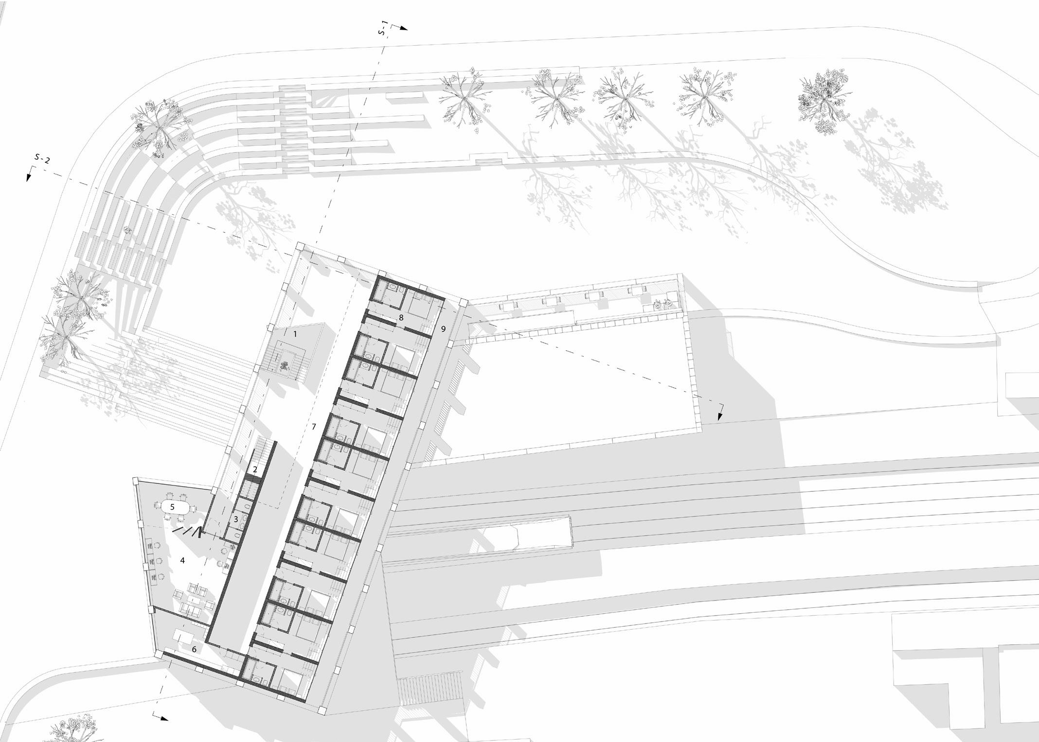
The project for the redevelopment of Gravesend Staton aims to provide the local community and visitors with an actve and safe staton, no longer isolated from the rest of the city and devoid of life and actvity. In additon to reconnectng the staton to the street level, eliminatng the shadowed parking areas that made it dangerous, the project creates new green spaces that provide access to the platorm level and a new square surrounded by seatng areas and shops. The designed structure, besides accommodatng the new platorm access, will feature a new restaurant and a hotel to make the staton a safe and vibrant place, even in the evening. A design developed during the frst semester of the same academic year laid the
groundwork for this new project, creatng contnuity between the two and infuencing the key principles and elements of the new design. The project from the frst semester was located along the Thames coast and aimed to reconnect the Gravesend community to the riverbank and its historic pier. The project incorporated key elements of the original bridge, partcularly the arch, which has returned as the main element in the redevelopment of the railway staton. In both projects, the arch is explored in its form and functon, making it the true protagonist of the structure. Gravesend, unfortunately considered a dangerous city, will enjoy a new train staton flled with life and actvity, rather than just being a simple transit hub.

This inital sketch explores the spaces and actvites that the new Gravesend staton will ofer to its citzens and travelers. What was once just a notorious staton, isolated from the rest of the city now aims to provide a new where place to go, not only to catch a train but also a place to gather and engage in actvites. Maintaining the arch as the main
element, also present in the pedestrian bridge design, built in the early 20th century (removed in 2013) and as in the project from the frst semester, the new design intends to incorporate plenty of greenery, shops, cafes, a restaurant, and a hotel where people can also work and partcipate in conferences.

For the compositon of this project and the previous one, a mix of sketches and shadow exploraton have been used to reach the fnal result. The physical model, along with the sketch that brings it to life and makes it more communicatve, laid the foundatons for the fnal design of the staton. From there, it underwent various changes and improvements in response to the project’s needs. The original arches in the city were made of bricks, which are stll preserved in the region. However, due to the size of the plot and the
project, as well as the limited availability of original bricks, unlike the previous design, the main structural and design material is replaced with stone sourced from a limestone quarry located in Kent, not far from Gravesend and visible from the train during the journey to the city. Inspired by the constructon techniques used by Amin Taha in the project ‘15 Clerkenwell Close’ and publicatons from the Building Centre on The New Stone Age, the stone is used without extensive processing, thereby minimizing costs and CO2 emissions.


The load-bearing structure is placed on the north side of the railways and rises for three foors divided in two diferent volumes, one parallel to the rail track and one that looms over it. On the horizontal plan, the two volumes create an obtuse angle that opens on the south side of the landscape. Rising above a concrete plinth are the limestone columns, which are not merely self-supportng, but also bear the loads of the cross laminated tmber foors. Internally, a lightweight bearing structure of glue-laminated tmber columns and beams reduces the loads on the walls and allows fexible layouts. The foundatons, the extension of the bridge that spans the train tracks, and the
walls of the stairs are the only elements made of concrete. The other materials are, as stated, stone and cross-laminated tmber. Stone and CLT are combined more environmentally sustainable than concrete alone. In fact, inherently stone has zero carbon footprint. It is the energy used in quarrying, preparing and lifing the stone into place where CO2 builds up. Typically, if the quarry is in the same country, then the stone superstructure will have saved 95% of the embodied CO2 against its steel or concrete equivalent. As tmber has carbon sequestraton propertes, combining stone as exoskeletal super-structure and CLT foor plates will produce a CO2 negatve building today.




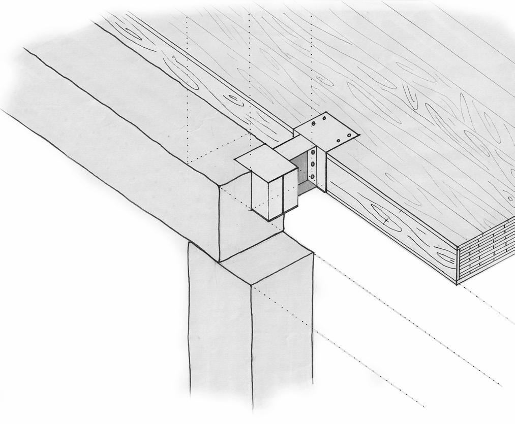
Regarding other aspects of the environmental strategy, the chosen technological system once again employs dry stratfcaton, aiming for energy and cost savings while allowing for a signifcant reducton in materials used, most of which are recyclable and highly efcient. In the adjacent illustraton, it is shown how limestone is utlized
in this design, serving as an exoskeletal structure. Besides being self-supportng, it is capable of sustaining the various cross-laminated tmber foors through a specifcally designed joint (nternally, a lightweight load-bearing structure consistng of columns and glulam beams reduces loads on the walls and enables fexible layouts).
Regarding the aesthetc of the stone, the columns and beams will have three diferent fnishes given by the diferent extracton modes. The frst type of fnish is given by the inducted breaking of the stone, producing a raw and natural result. This method creates large blocks that will then be divided with the use of the next methods. The second type of fnish is given by the manual tools stll used for the division of the stone. With this method, long chisels are hammered into the stone causing it to crack. The third extracton method is the one that creates the smoothest and most


artfcial fnish thanks to the precise water jet extracton machines. AII three types of fnishing will be present on each element as all three extracton methods are used for the creaton of the columns and beams. The main structural systems used for this design are three: 1) When the height of the level is sufcient to be crossed by a single column, the beams are used to create stability. 2) ln the case of a double height, where the beams cannot be used, the stability will be given by a metal core. 3) The term of the structure will be supported thanks to the use of the arches.


MORE ABOUT MY WORKS
This portolio provides a brief summary of some of my academic work. For a more detailed look at the projects and to explore some of my other works, you can click on the various ttles here to view the complete PDF fles online.


London narrowboat club. London
Academic Yeard: 2
Observatory on the Thames. London
Academic Yeard: 2
The interrupted link.
Gravesend
Academic Yeard: 3
Gravesend staton-
square. Gravesend

Academic Yeard: 3
Light and space, shadow and void.
Year: 3
Dissertaton
Hyphen. Practce report

Year: 3

