13 minute read
5. Life Cycle Assessment
5. Life carbon assessment
This chapter provides the foundation and method of calculating embodied, an adaption of the guide
Advertisement
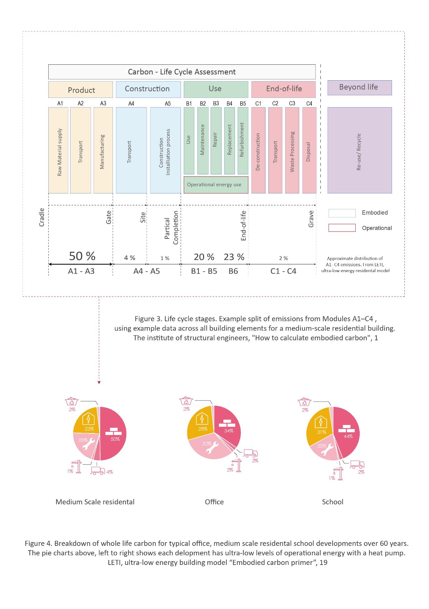
listed as ‘RICS professional standards and guidance, UK: Whole life carbon assessment for the built environment’25 , Figure 3 represents typical scope of procedure spanning the complete life cycle of a
medium scale residential building(s). The resulting data can be used as a tool by designers to make
meaningful comparisons to determine the emission output and inform design iterations, specific of
each building element to effectively reduce in an individualistic capacity to net zero carbon. Each
resulting data point can vary drastically based on the building construction typology and the
definition and characteristic of materials specified. The references to embodied carbon data used in
this study are UK aligned to distinguish the clarity of materials where the composition, sourcing and
manufacture are often left to the discretion of individual(s), regulated by state governments.
The amount of carbon is represented by the kilogram per carbon dioxide approximation, or kgCO2e, also known as the global warming potential26 .
Product stage. The modules A1-A3 takes into consideration the kgCO2e defined through material
sourcing, processing, and manufacturing. This concerns materials that are both raw and complied
into components, The carbon is also measured between transportation up until the material is brought to site. This stage does not consider the amount of kgCO2e which has been recycled in the
materials components.
Construction stage. A4 & A5 considers the carbon released during the shipping of materials to the
construction site. This also includes any preparation needed to house the materials in relation to
maintaining optimal functionality.
Use stage. B1-B7 calculates the carbon released in relation to the operation of the building. This
scope covers the required energy and water demand to operate the building as well as maintaining
the functionality of materials.
End of life stage. C1- C4, considers the carbon released during the end-of-life phase in a building.
From demolition to disposing of materials.
Beyond the life cycle stage. This final stage responds to carbon that can be recovered during the life
cycle.
25 Sturgis, Simon. "Whole life carbon assessment for the built environment". (London: Royal institution of chartered
surveyors. 2020)
26 Gibbons. O. P & Orr. J. J, “How to calculate embodied carbon” (London: The institute of structural engineers, 2020) 1,2
As specified in Figure 2, for a low energy, medium scale residential development the largest single
contributor of carbon emissions occurs during the ‘production of materials’ (A1 – A3), 50 percent. In
comparison a development’s ‘operational use’ (B6), is typically half – 23 percent ‘product stage’,
when factoring the ‘maintenance, repair, replacement, and refurbishment of materials’ (B1 – B5) the
embodied carbon is significantly the largest emitter at 70 percent. A ‘whole life carbon assessment’
considers all building related elements; including temporary works, substructure, superstructure, finishes, and fitting(s), 27 which is completed throughout the RIBA design stages of work; however, this report will consider the minimum scope of investigation28 that covers only; substructure and
superstructure (A1 – A3), due to the forementioned lack of awareness in embodied carbon
materials.
5.1 Working methodology
The method used in an embodied carbon calculation can be approached in multiple ways, an
architectural practice will in sub-contract an environmental technician - freelance or otherwise,
using a plugin for multiple BIM modelling software(s) to provide an assessment subject to the proper
layering of information present in the model. This investigation will primarily preform the manual-
based technique to engage with the historical narrative more accurately due to the specification of
historical materials.
The fundamental principle of an embodied carbon calculation is to multiply the quantity of each
material by a carbon factor:
Material quantity (kg/ m3) x carbon factor (kgCO2e/kg) = embodied carbon (kgCO2e)29
This formula represents the direct representation of quantifiable release of carbon into the
atmosphere, both the structural and constructional materials will be considered relative to the floor area (1m2)).
27 Sturgis Simon, “Whole life caron assessment for the built environment, RICS professional statement”, (London: Royal institution of the chartered surveyors (RICS), 2020), 9 28 Ibid, 8 29 (Gibbons. O. P. & Orr. J. 2020) 4
5.2 Structural Columns, Figure 3:
Material: Cast concrete in-situ
Thickness: 300mm
Strength Class: C40/50 Mpa
Portland Cement content: CEM 1 (100% Portland cement)
Carbon Factor: 413 kgCO2e/m3
Firstly, we must consider the weight for each individual material to find the total quantities of building fabric. This can be achieved by either calculating the Volume (m3) or weight (KG) in
kilograms, which is dependent on the profile edge of the component. The Villa Savoye uses cylindrical columns for structure, [formula has been adapted30] to consider (r = radius of column
thickness). To calculate the total volume of the ‘structural columns’, we would multiply the volume
of 1 column by the number of columns.
(π x r2 (m) x height (m)) x No of columns = Volume of structural columns (m3)
The Villa Savoye contains two variations in height of ‘structural columns’; we would then have to
differentiate the columns into two elements and add the sum of them together.
((π x 0.1502 x 6.8) x 29 columns) + ((π x 0.1502 x 3.4) x 3 columns) = 15 m3
Typically, the dimensions which include the thickness and height of the columns would be specified
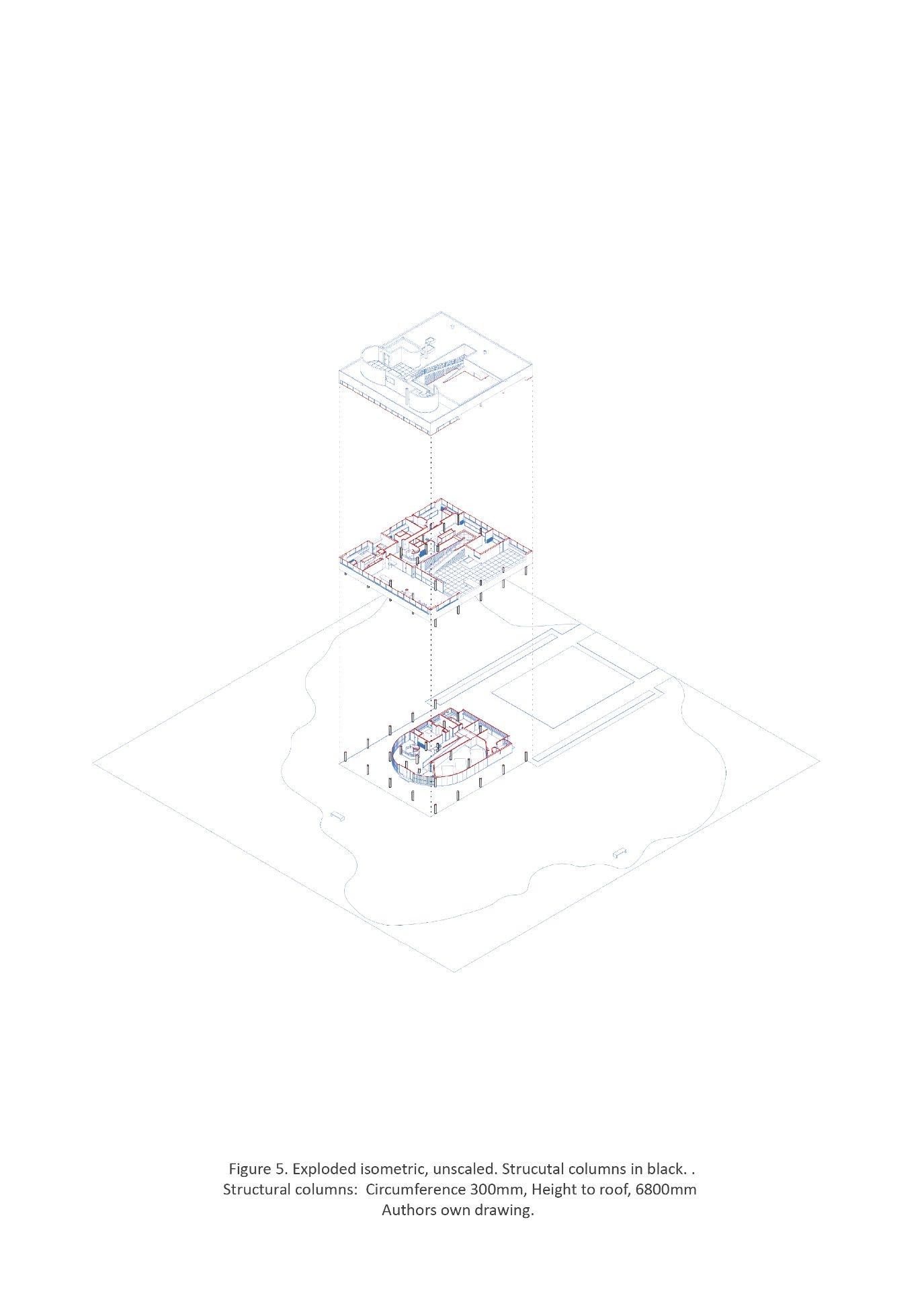
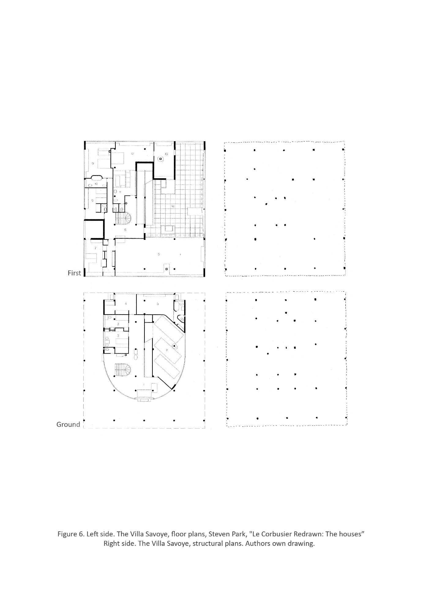
in the set of original structural drawings or product specifications supplied by the architect, however no record of these exists31. Therefore, the author has consulted secondary sources32 to calculate the
number and height of columns, figure 5.
Secondly, we need to obtain the ‘Embodied Carbon Factor’ (ECF). Similarly, this data is normally
specified before the building is constructed and listed under product specification(s) in the ‘Environmental Product Declarations’ (EPD) by the manufacturer33. However, the ECF can also be
obtained from the ICE database. The ‘Inventory of Carbon and Energy’ is a database for building
30 Appendix 1
31 Espion Bernard, “Building Knowledge, Constructing Histories”, (United states: CRC Press, 2018) 373 32 Steven Park, "Le Corbusier Redrawn: The houses", (New York: Princeton Architectural Press, 2012) 150-153 33 (Gibbons. O. P. & Orr. J. 2020) 14
materials which contains original energy factors that provide insights to the energy consumed to make a building material (A1-A3) 34 .
Bernard Espion, editor of ‘Building Knowledge, Constructing Histories’, presents a series of articles that to contribute to the latest research in the field of construction history35. Most relevant;
‘Exploring the visual material within the building process of the Villa Savoye’, by Veronique Boon and
Benedicte Gandini to provide the contextualisation of the building process and the justification of
ECF values used for materials.
The article functions as a narrative and tool to relate the importance of visual documentation of
architectural building(s) and icon, the Villa Savoye. Boone and Gandidi’s research provide unedited
insights to the construction of Villa Savoye through a series of amateur films shot and produced by
Ernst Weissmann, collaborator, and employee in the ‘Atelier Le Corbusier’ which films have only
been recently restored and digitalised for the public. The raw footage is converted into still images
which relate the deep, humanistic construction of the Villa Savoye where Weissmann captures
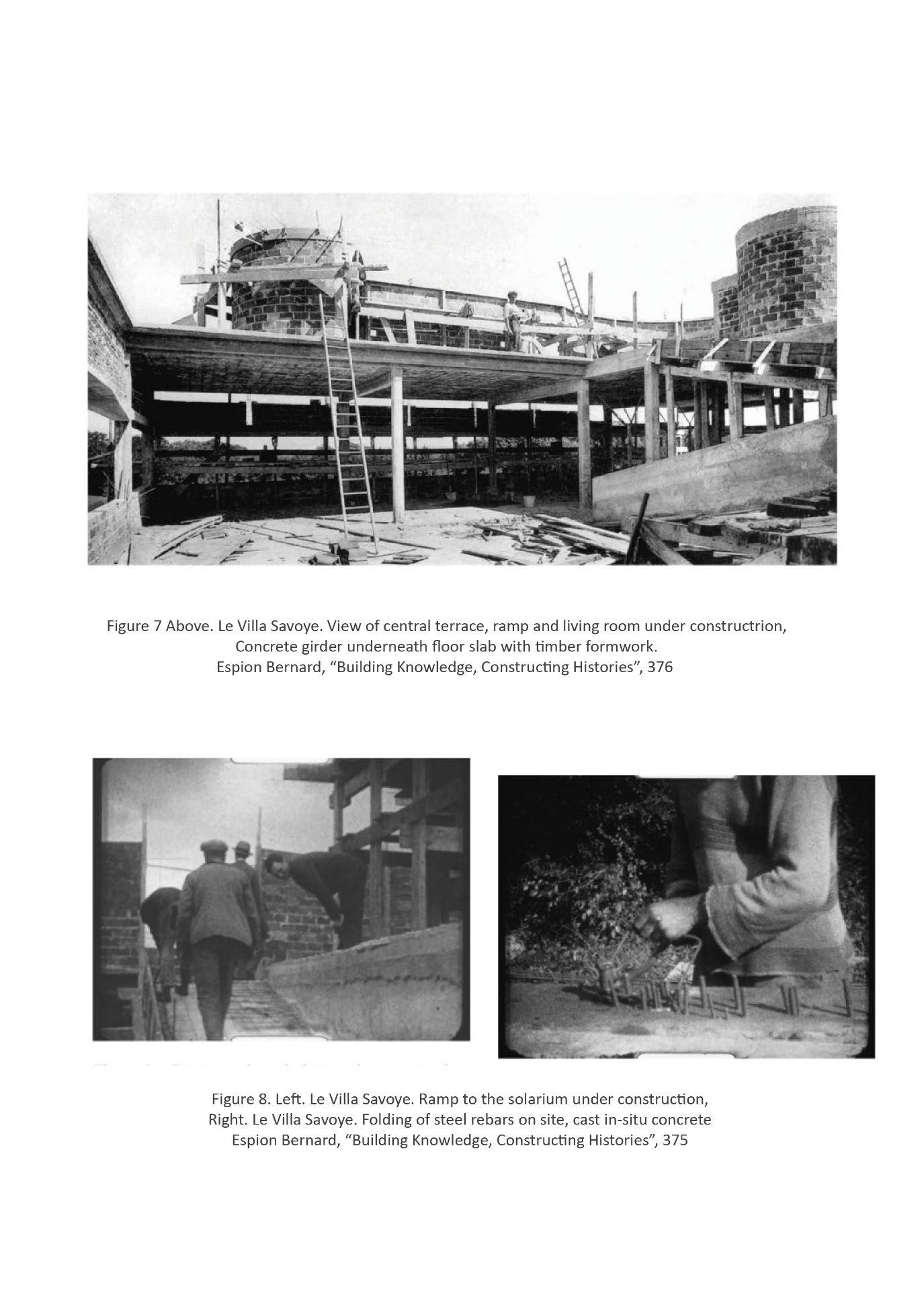
craftsmen, not only completing their contractual work but also portrays their faces, laughing and personalising them as potential equals36. Visible throughout the stills are the individual tasks coordinated by the architect, depicting the pouring of in-situ concrete into timber formwork37 to
visually document the construction techniques used in the cross examination of material
characteristics informing the ECF.
“The concrete composition [floor slabs] indicated in the offer as well as on plan, is fixed at 0.800 m3 gravel: 0.400 m3 sand and 300 kg of cement”38 .
Considering 300 kilograms of cement is equal to 0.3 m3, we can reasonably assume that the ratio of
gravel : sand : cement is equal to 8:4:3. Therefore, the concrete used in the floor slabs have a carbon factor of approx. 370 kgCO2e/m3 based upon the information supplied from the ICE database,
detailing an equivalent material composition that pertains the consistent average strength class of 25/30 MPa used in concrete flooring.
34 Jones, Craig & Hammond Geoff, “Embodied Carbon the ICE Database”, Circular Ecology, 03/2022, https://circularecology.com/embodied-carbon-footprint-database.html 35 (Espoin 2018) 36 ibid 375 37 Ibid 375 38 Ibid 379
Then, “The offer specifications set by the contractor mention the calculated weights on the slabs, 1.5 kN/m2 at private rooms, 2.5 kN/m2 at reception rooms and terrace except for 2 kN/m2 for the solarium and 1 kN/m2 for the roof… The [steel] reinforcement bars used are mostly 6mm, 8mm, and 10mm… as is the covering concrete, varying between 5 and 8 cm”39 .
The description of the forces exerted on the different rooms and the variation of thickness from
both the steel reinforcement and concrete floor slabs suggest that dependent on the load and
function of the building, the strength grade of the materials would vary in the reaction to differing
load capacities.
Using this method of analysis, we can link the known materials used in the Villa Savoye with the characteristics observed in the article40. The ICE database contains comments for each material
relating to their specification, to aid in assigning the correct ECF.
For example, “In-Situ Concrete, With CEM 1 (Portland cement content 100%),, 40/50 MPa, embodied carbon 413 kgCO2e/m3 assumed 420 kg cementitious content per m3 concrete. Possible uses: structural purposed, in-situ floors, walls, superstructure”41 .
Suggesting, the Embodied Carbon Factor would then be assumed to be 413 kgCO2e/m3 and have a strength class of 40/50 MPa in the ‘structural columns’. The calculation is then divisible by the gross internal floor area (m2):
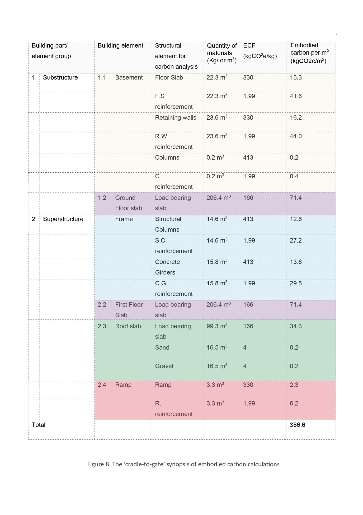
The Cradle-to-gate (A1-A3) calculation for ‘structural columns’:
Volume (m3) x carbon factor (kgCO2e/kg) / total floor area (m2)
= embodied carbon (kgCO2e/m2)
((π x 0.1502 x 6.8) x 29 columns) + ((π x 0.1502 x 3.4) x 3 columns) x 413 / 480)
= 12.6 kgCO2e/m2
39 Ibid 378 40 Ibid 41 Jones & Hammond “Embodied Carbon the ICE Database”
5.3 Steel reinforcement in structural columns.
Thickness: 10 mm
Weight: 450 kg/m3
Volume: 14.6 m3
Carbon Factor: 1.99 kgCO2e/m3
Weissman film slide’s capture the use of steel reinforcement throughout Villa Savoye, identifying the thickness and steel mesh used of the period42, whereas (Ford 1989)43 informs us that the structural
columns themselves also use steel reinforcement typical to the building typology of Le Corbusier Villa’s during the 1920’s44 . To calculate the cradle-to-gate emissions of steel reinforcement within
the structural columns it follows a similar process previously,
(Weight (kg/m3) x volume (m3)) x carbon factor (kgCO2e/kg) / total floor area (m2)
= embodied carbon (kgCO2e/m2)
The quantity of materials is calculated by the weight multiplied by volume. The weight of steel reinforcement (450 kg/m3) and the carbon factor (1.99 kgCO2e/m3) 45 are considered the industry standard, which contains the thickness (10mm) mentioned by Boone and Gandidi46 .
(Weight (kg/m3) x volume (m3)) x carbon factor (kgCO2e/kg) / total floor area (m2)
= embodied carbon (kgCO2e/m2)
(450 x 14.6) x 1.99 / 480)
= 27.2 kgCO2e/m2
42 (Espoin 2018) 379 43 (Espoin 2018) 379 44 Ford. R. Edward, “The Details of Modern Architecture”, (Cambridge, Massachusetts: The MIT Press, 1989) 243 45 (Gibbons. O. P. & Orr. J. 2020) 12 46 (Espoin 2018) 379
Therefore, the total sum for Cradle-to-gate calculation (A1-A3) calculation for structural columns with
steel reinforcement in Villa Savoye:
12.6 kgCO2e/m2+ 27.2 kgCO2e/m2 = 39.8 kgCO2e/m2
5.4 ‘Concrete Girder’
Material: Cast concrete in-situ / Lost tile
Thickness: 500 - 800mm
Volume: 5.6 m2
Strength Class: C40/50 Mpa /
Portland Cement content: CEM 1 (100% Portland cement)
Carbon Factor: 413 kgCO2e/m3 / 330 kgCO2e/m3
Edward R. Ford describes the structural organisation of the Villa Savoye.
“Villa Savoye… [composed of] structural bays of 5 x 5 or 2.5 x 5 meters… the columns were displaced or split in two when in conflict with the other plan (most noticeable at the ramp that splits the centre
column line. The major girders (which pick up the loads of the minor beams created by the tiles) are
dropped below of the bottom of the Slab… the floor [a method of] reinforced concrete. It was, a ribbed slab created by the ‘lost tile’ process” 47
Firstly, it is critical to consider Le Corbusier’s ideal ‘free plan’48 which contributes to the tectonic
composition, role of taking loads and position of the ‘Concrete Girders’. Figure 7 illustrates the
structural component in composition – predominantly acting as secondary structure to counteract
the lateral load’s from the ‘Structural columns’. The concrete elements play a vital role in spanning
the columns to hold up the floor slabs, which result in the plan-free of loadbearing walls as well as
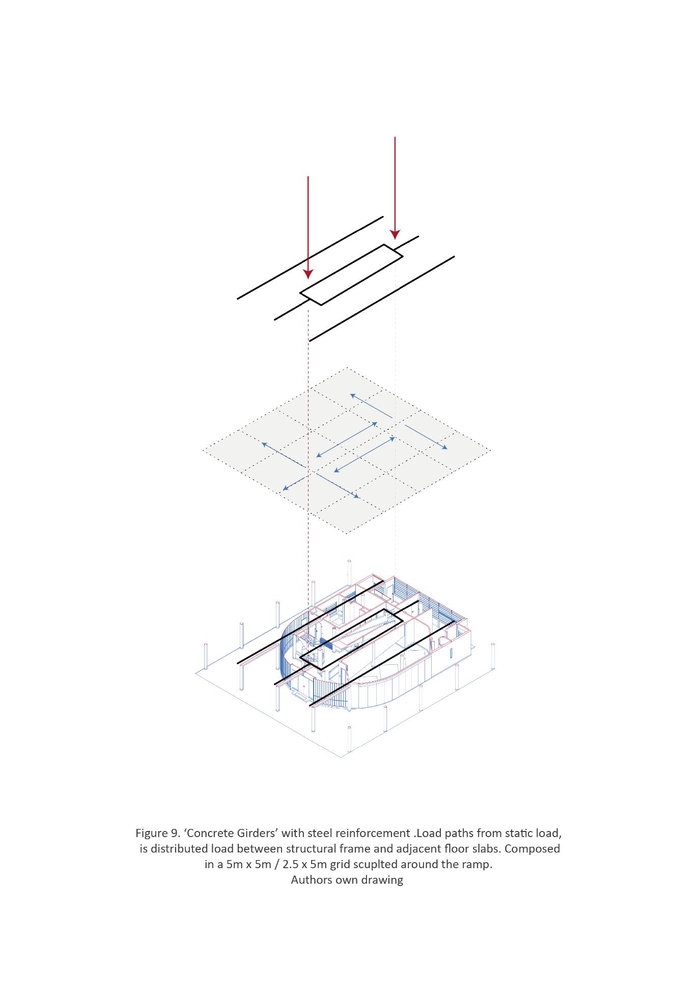
the facades. The Villa Savoye, is formed from a structural grid, defined in the variation of 5m x 5m or
2.5m x 5m which organises the position of ‘Structural columns’ and loads are transferred through
strategic points in relation to the spatial arrangement of rooms and the formation of the ramp, see
figure 7. This tectonic language produces a formula that can factor the building’s program and
atmospheric aspiration, where the simplistic structural arrangement can act as a catalyst to
manipulate space and form. The characteristic and secondly role the ‘Concrete Girders’ play in
carrying loads ensures the same strength to weight ratio as the columns, it would be difficult to
justify any change in material composition to conclude the ECF is consistent alongside the columns.
47 (Ford 1989) 243 48 (Corbusier 1986)2
The cradle-to-gate (A1-A3) calculation for Concrete girders as follows:
Volume (m3) x carbon factor (kgCO2e/kg) / floor area (m2)
= embodied carbon (kgCO2e/m2)
((Volume of row type 1 (m3)) x (No. of rows)) + ((Volume of row type 2 (m3)) x (No. of rows))
x (No. of floor) x carbon factor (kgCO2e/kg) / total floor area (m2)
= embodied carbon (kgCO2e/m2)
(((0.3 x 0.3 x 25) x 2 rows) + (0.3 x 0.3 x 37.5) x 1 row)) x 2 floors) x 413 / 480
= 13.6 kgCO2e/m2
5.5 Steel reinforcement in ‘Concrete Girders’
(Weight (kg/m3) x volume (m3)) x carbon factor (kgCO2e/kg) / total floor area (m2)
= embodied carbon (kgCO2e/m2)
(450 x 5.6 x 1.99 / 480)
= 10.4 kgCO2e/m2
Therefore, the total sum for Cradle-to-gate calculation (A1-A3) calculation for concrete girders with
steel reinforcement in Villa Savoye:
13.6 kgCO2e/m2 + 10.4 kgCO2e/m2 = 24.0 kgCO2e/m2
5.6 Floor Slabs
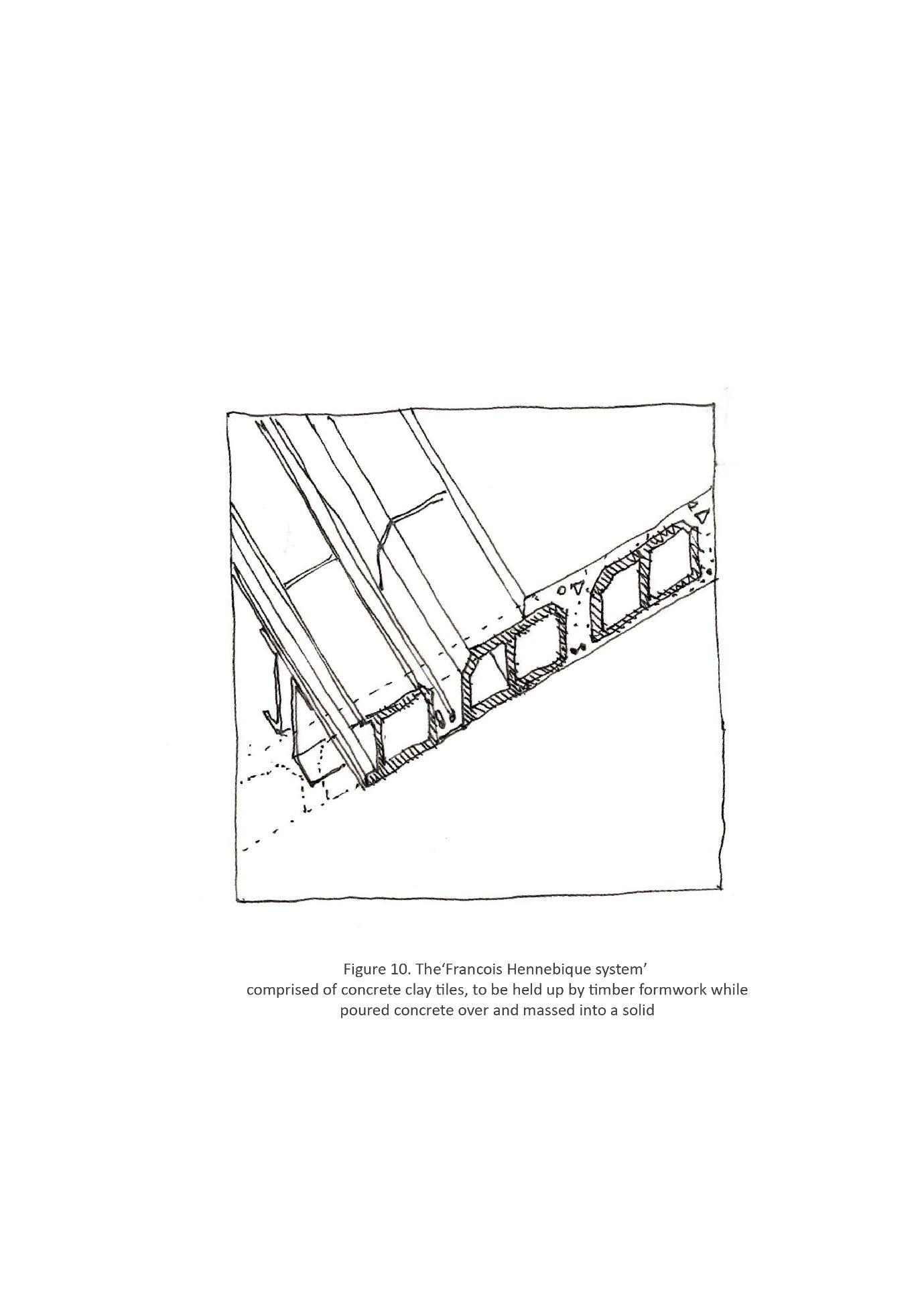
The floor system used in the Villa Savoye, acts as a solid mass and tertiary structure and a
modification of the ‘Francois Hennebique system’ figure 10. - comprised of concrete clay tiles, to be
held up by timber formwork while poured concrete over and massed into a solid. This system is
dependent on Corbusier’s ‘free plan’, without the supporting ‘Concrete Columns’ or ‘Concrete
Girders’ the slab would fall into itself from tensile loads.
The Floor slab(s) are made up of the ground, first and roof slabs. The ground and first floor use the
same ‘lost tile’ process of structure and composition whereas the roof has been modified in an effort
to prevent the ingress of water with the addition of several layers; Bituminous mastic (durum fix), sand, and gravel49 .
The cradle-to-gate (A1-A3) calculation for floor slabs and as follows:
Volume (m3) x carbon factor (kgCO2e/kg) / total floor area (m2)
= embodied carbon (kgCO2e/m2)
(Volume of ground floor (m3)) + (Volume of first floor (m3))
x carbon factor (kgCO2e/kg) / total floor area (m2)
= embodied carbon (kgCO2e/m2)
(21.5 x 19.2 x 0.5) + (21.5 x 19.2 x 0.5) x (166)
/ 480
= 168.3 (kgCO2e/m2)
The cradle-to-gate emissions of roof slab, sand and gravel are negligible. Therefore, the total sum for
Cradle-to-gate calculation (A1-A3) is as follows.
168.3 kgCO2e/m2+ 40.4 kgCO2e/m2 = 208.7 kgCO2e/m2
49 ibid 249
