3 minute read
Making it work: development of F-WTSA


Although F-WTSA was a French Concorde, British engineers from the British Aircraft Corporation (BAC) worked with their French counterparts at Aérospatiale, in Toulouse, to develop the aircraft. BAC support engineer Rowland White recalls a couple of the challenges involved in preparing Sierra Alpha for flight.
I had worked in the summer of 1968 in the engineering office at Filton, but in the early spring of 1969 I was transferred to Toulouse. From then on I was no longer involved in the design of the aircraft; my job became to “make it work”.
It was almost four years later that FWTSA, the second pre-production aircraft, was handed over from the design office to us, the systems development team in Toulouse. Now, on January 10, 1973, it was our task to complete the development work.
A new form of Concorde
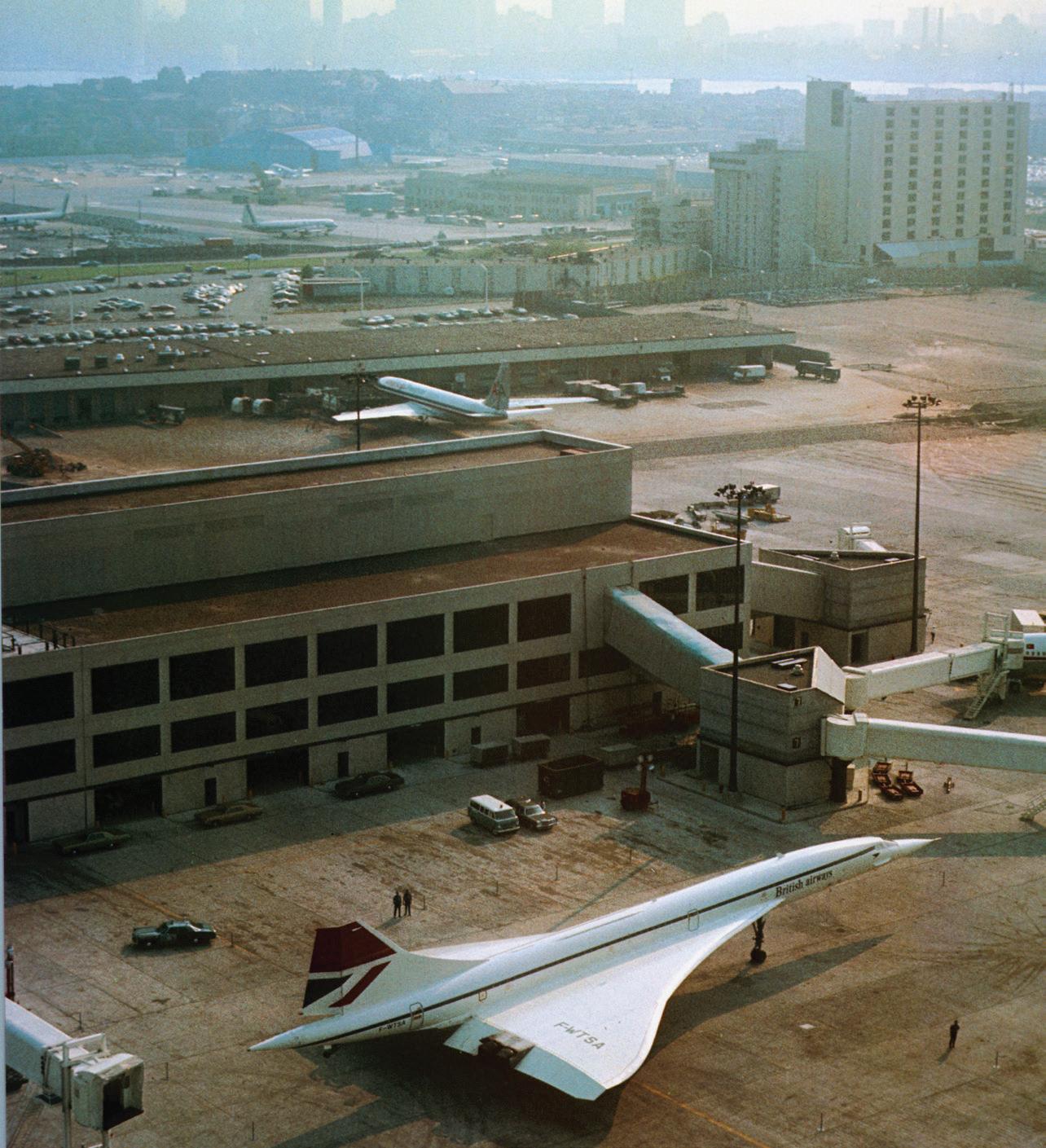
This aircraft was really something new. It incorporated all of the technical and systems lessons from the first three aircraft, but it was a striking departure externally. It showed us a new grace beyond that of its predecessors. New shape, new dimensions, new jet nozzles, and a longer tail. In appearance, F-WTSA was the most production-like of the first batch of aircraft. Following its maiden flight, it soon began a series of visits that highlighted this issue.
Anti-collision beacons
The old anti-collision beacons, which had retracted into the fuselage on previous aircraft, were replaced with flashing xenon tube units, and here came my first problem. After only a few flights, the tail-mounted beacon failed. I had it removed, and found it to be in bits. So it was replaced, and after another couple of flights, this unit was also found to be in bits.
I contacted the manufacturer, and (not for the first time in the programme) I was accused of sabotaging their product! The cause?
Variations on a theme
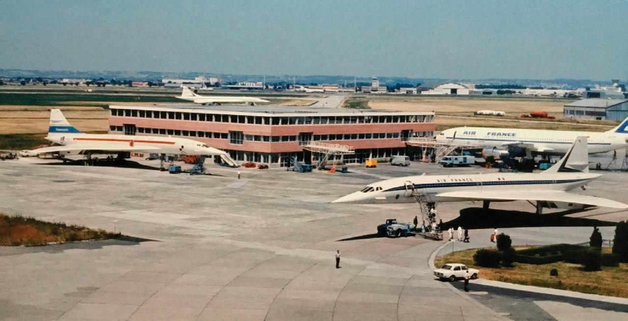
Three forms of Concorde on the tarmac at Toulouse: French pre-production aircraft 02 (front, right); his British counterpart 101 (front, left); and production Concorde 201 (F-WTSB) in the background. Some differences between the British and French pre-production aircraft, especially regarding the tail, are evident.
The longer tail cone of this aircraft meant that the beacon was now in the “noise cone” of the afterburners for engines 2 and 3. The cure? Move the electronics further back into the aircraft’s tail.
Ground power unit (GPU)
Unlike the production aircraft, the two prototypes, and the first pre-production aircraft, SA has an additional electrical connection for
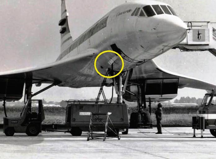
The site of the problem
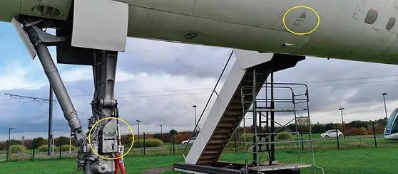
The location of the ground power receptacle on Sierra Alpha’s fuselage is shown here, ringed in yellow. The receptacle could only be accessed by ladder.
the parking GPU. During visits to airports with French prototype F-WTSS, and early visits with FWTSA, the airport ground crews were often not prepared for the location of the electrical ground power receptacle on the aircraft. This was on the fuselage, as it always is on an airliner. On conventional aircraft, with their short nose landing gear, this is easy to reach. However, Concorde’s long nose leg meant that the fuselage was too high to reach unless ground support crew used a ladder to access it and connect the power. Many airports were not prepared for this, and often there was considerable delay whilst someone went to search for a suitable ladder.
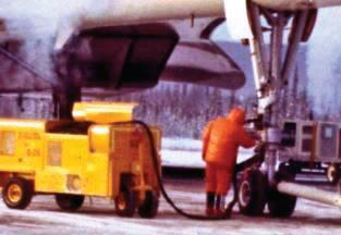
Consequently, Aérospatiale decided to add a second ground power receptacle on the nose landing gear itself, to allow a ground generator to be connected even in airports that were not equipped with service steps high enough for connection on the right side of the fuselage.
Engineering challenges
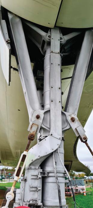
Designing this receptacle was not a simple matter, as by definition the landing gear moves, contracts, folds, etc. Additionally, we had to position the receptacle so that it would not get blocked or showered with snow, ice, or heavy rain. Since electrical power supply was a BAC responsibility, the task of engineering the fitting fell to me, supported by my draftsman Pete, who had to produce the detailed drawings of the scheme.
The first issue, rather obviously, is that whatever we designed had to avoid interfering with the function of the landing gear, including retraction. It made sense, therefore, to fit the receptacle at the bottom of the nose leg, above the steering unit. We would make a machined aluminium
The
Left: enclosure, to go on the right-hand side of the gear, facing right. This orientation and location would mean that the receptacle was on the same side as the existing fuselage receptacle (which would remain fully functional). Additionally, the new receptacle would not face directly forwards, thus protecting it from debris and weather during take-off and landing.
The cables could not extend to or beyond the oleo, to avoid fouling the movement of the landing
A one-off solution
gear. However, they would need to run up the front of the nose leg, in order to be clear of potential contact with any metalwork, especially when closed. Therefore, a system of protective shrouds was designed to protect the cables at all times.
The receptacle that we made was located approximately 1.70 m from the ground on right side of the nose gear strut. This modification was never used for the production aircraft, due to the addition of totally unnecessary weight.
The two GPU receptors remain in place on Sierra Alpha today. In the image below, they are ringed in yellow.