6 minute read
HYDRAULICS
Pressure vs. Flow: Understanding the Difference
Advertisement
As a hydraulic instructor and consultant, I have met thousands of people whose job consists, at least in part, of the maintenance and repair of hydraulic systems. The number of hydraulic troubleshooters I have come across, however, I can count on the fingers of one hand. For the most part, I have encountered a lot of excellent hydraulic parts changers. These are people who have worked on and around hydraulic systems for so long that they know changing a specific
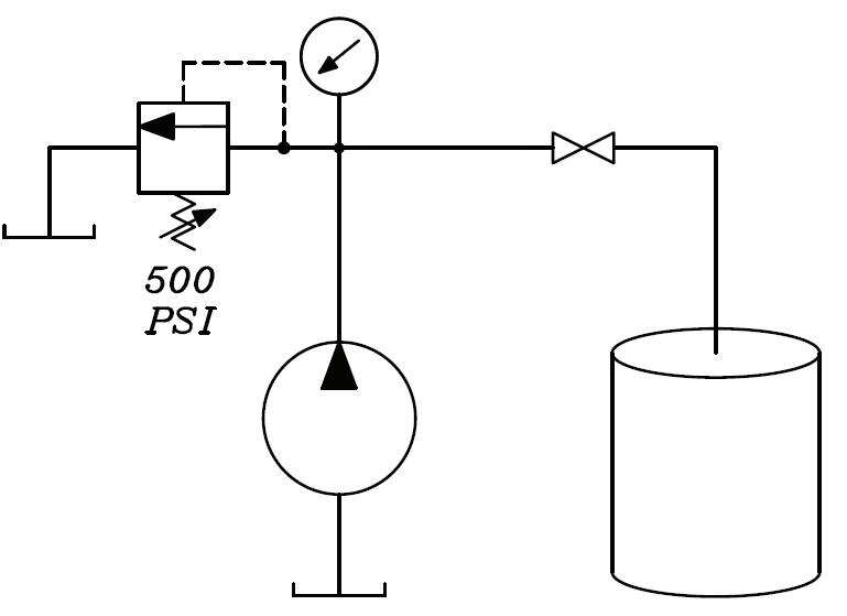
In this schematic, a fixed-displacement hydraulic pump is represented by a circle, with a filled-in arrowhead indicating liquid output.

part typically corrects a certain problem. They may or may not know exactly why this is, but they know from experience that replacing this part fixes the problem. Now I don’t mean this in a derogatory way. Someone with that level of experience is valuable, but it isn’t troubleshooting; it’s parts changing. It works fine whenever changing a part does in fact correct the issue. The trouble

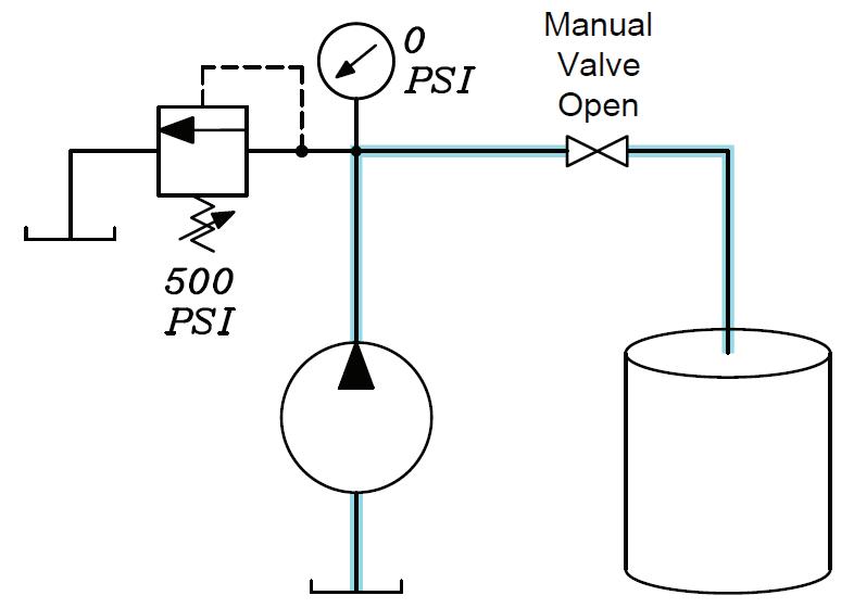
When the pump is turned on, the path of least resistance is to the drum and not through the relief valve.

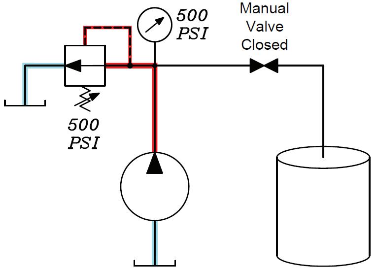
comes when a parts changer changes a part and it doesn’t fix the problem. What do you suppose the parts changer’s next course of action may be? If you said “change something else,” you would be correct. This schematic shows a closed manual valve, which blocks flow to the drum.
Frequently, the parts changing process continues until one of two things occurs: either the machine is repaired, and everyone rejoices, or the system is put into such a state that someone must be called. Quite often, that someone is me. While it is possible to repair the system this way, it is also possible to add a problem or two whenever a component is replaced that was not bad. Usually, by the time I am called to help, a considerable amount of parts changing has occurred, and what began as something simple may have progressed into multiple issues which can be very time consuming to diagnose.
Pressure or Flow? If I had to pick a single concept that keeps most parts changers from becoming troubleshooters, it would be the failure to understand the difference between pressure and flow. It is not uncommon to hear the terms used interchangeably, as though they are synonyms. They aren’t. I often hear the complaint that a pump isn’t putting out as much pressure as it should, implying that the pump is supposed to deliver pressure.
A common assumption is that if the pressure is low, the pump must be bad. This is not the case. The pump doesn’t pump pressure. The pump delivers a rate of flow. The single function of the pump is to take fluid from one place and put it somewhere else. Pressure is the result of resistance to flow. In our training classes, we use the simple schematic shown on page 20 to explain this concept.
A fixed-displacement pump is the simplest type of hydraulic pump. It is turned by a primary mover, generally an electric drive motor or, in mobile equipment, the same engine that moves the machine. The amount of flow is determined by the displacement and speed of the drive motor. By “displacement,” I mean the amount of fluid delivered for each full rotation of the pump. On typical industrial systems, the pump is turned at a constant speed and therefore delivers a constant amount of flow. When the pump is started, oil is moved from the reservoir and into the system. The higher the flow rate, the faster the actuator will move.
If you trace the flow from the pump, you reach a “T” in the line. Whenever you follow the flow on a schematic and arrive at a line split, you must track the flow in both directions to determine the path of least resistance. Hydraulic fluid always takes the path of least resistance. If you trace the flow to the left, you encounter a relief valve symbol. The relief valve is represented by a single square with an arrow indicating the direction of flow. Notice the arrow does not touch the inlet or outlet port. This signifies that the relief valve is normally closed and blocking flow.
The “zigzag” line at the bottom of the relief valve symbolizes a spring. A good way to think of a relief valve in a schematic is to think of the spring pushing the arrow up away from the ports, holding it closed. This means that, in order to open the valve, something must push down on the arrow harder than the spring is pushing up. Also, note the dotted line. In hydraulic schematics, a dotted line usually represents a flow path that is somewhat smaller than that of a solid line, typically a drain line or a pilot line. The one shown in the schematics on the left is a pilot line connected immediately upstream of the valve. Whatever pressure is in the main line will be present in the pilot line.
Returning to the spring, notice the diagonal arrow. In schematic symbols, a diagonal arrow means that its related component is variable or adjustable. In this case, the relief valve has an adjustable spring and has been adjusted so that a pressure of 500 pounds per square inch (psi) will develop enough force to compress the spring and open the relief valve. The resistance in this direction is therefore 500 psi.
Tracing the flow to the right, you encounter a symbol for a manual valve. This could be a ball valve, gate valve, butterfly valve, etc. The valve can be open or closed. The notation indicates that it is open, so there is no resistance in this direction. The line terminates into an open drum. When the pump is turned on, as shown in the schematic at the top of page 22, the path of least resistance in this case is to the drum, not through the relief valve. The pressure reading on the gauge is 0 psi.
Clearly, the reason the gauge reads so low is because there is no resistance in the system. However, I have seen many pumps replaced for no other reason than because the pressure in the system was low. Over the years, I have received numerous phone calls that started out, “Well, I have changed the pump, but my pressure is still low. What else should I look for?”
In fact, a pressure problem in a hydraulic system is rarely the pump. It is almost always another bad component in the system. The pump should never be the first component to try but rather your last resort when a pressure problem exists. In the example shown, replacing the pump would deliver exactly the same result.
In the schematic at the bottom of page 22, the manual valve has been closed, blocking flow to the drum. The only remaining flow path is through the relief valve. For fluid to pass through the relief valve, a resistance of 500 psi must be overcome. Once pressure builds to 500 psi, flow is
delivered through the relief valve and back to the tank. On many occasions, I have heard remarks such as, “My pump is putting out 1,500 psi.” This illustrates the misconception that pressure originates at the pump. As you can see, what is being read on the gauge is not how much pressure the pump is putting out but rather the amount of resistance currently being overcome in the system. Without a firm understanding of this concept, becoming a troubleshooter is impossible. ML
About the Author Jack Weeks is a hydraulic instructor and consultant for GPM Hydraulic Consulting. Since 1997 he has trained thousands of electricians and mechanics in hydraulic troubleshooting methods. Jack has also taught radio-wave propagation for the U.S. Air Force and telecommunications equipment operation and repair for the Central Intelligence Agency at American embassies overseas.


