14 minute read
Lubricant Selection


Paul Farless | Noria Corporation LUBRICANT SELECTION
Factor: S4M
Advertisement
Cracking da Vinci’s Code:
Understanding Friction and Friction Modifiers
More about this ASCEND™ Factor
Factor:
S4M — Consolidation and Optimization
Level:
Management and Training(M)
Stage:
Condition Monitoring, Lubricant Analysis and Troubleshooting
About:
Establishing a lubricant consolidation process of optimizing the number and types of lubricants used will assist in keeping up with ever-evolving lubrication requirements without affecting machine performance or security.
Learn More:
noria.com/ascend/ Tribology is derived from the Greek root “τριβ” meaning “I rub,” which describes the science of rubbing when followed by the Greek suffix “-ology.” Today, this term simply refers to the study of lubrication, friction and wear. Friction should be treated as an enemy when it comes to machine reliability. When friction occurs, the mechanical energy is converted into heat. This heat, when combined with mechanical interactions, leads to wear, vibration and noise. These symptoms should be monitored on a daily basis, as they are the reason why we utilize friction modifier additives in our lubricants. This article dives into the different types of friction along with the role of friction modifiers to help you determine if they are right for your lubrication needs.
Types Of Friction
Leonardo da Vinci, a tribology pioneer, first discovered the basic laws of sliding friction back in 1493. These are the four types of friction he studied:
1. Sliding
a) For example, simply rubbing your palms together is sliding friction. b) In industrial settings, we see sliding friction in Journal
Bearings, Slideways, Gates, etc.
2. Rolling
a) A heavy ball rolling across the floor will create rolling friction. b) Rolling element bearings, one of the most common mechanical designs, can experience rolling friction.
3. Static
a) Pushing up against a heavy desk before it begins to slide is static friction. b) Similar to sliding friction, static friction is the force that holds the object at rest until the force of static friction is overcome and the object starts to move.
4. Fluid
a) The resistance felt when stirring
a fluid or a boat pushing its way through the water, is called fluid friction or sometimes called “Viscous Resistance.” b) Fluid Friction is a common type of friction often found in industrial machines that require lubrication.
A microscopic view of these surfaces in relative motion reminds us, no matter how well-machined, that each surface contains tiny, jagged asperities.
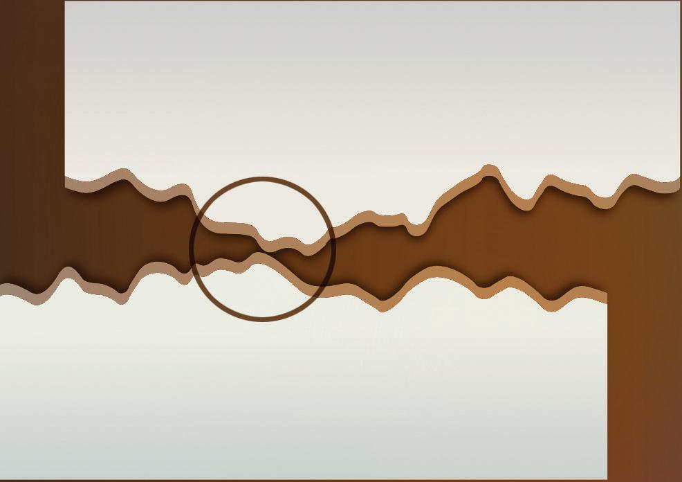
Asperities
Asperities are the rough, microscopic peaks on what is otherwise seemingly smooth surface. Even if the surface has been machined to a mirror finish, it will still have asperities. This is the exact point that friction and wear begin. When the asperities on each surface contact each other, friction is created. This is also the point where fluid friction comes into play in the form of good old lubrication.
In industrial lubrication, we pay a lot of attention to fluid friction, but, believe it or not, we deal with all four types of friction on an almost daily basis. We simply may not see it because it is happening within a component — like ball bearings rolling inside of the race in their housings or sliding friction at the pitch line in the gear teeth of your gearboxes. As friction continues, some asperities become dislodged and tumble in the gaps between surfaces, creating a third body. This gives way to a term known as “three-body abrasion.” This third body represents the aggregate of all particles between the two moving surfaces and with a relative motion of its own.
Friction Modifying Additives
1. Organic Friction Modifiers (OFMs)
a) OFMs are amphiphilic surfactants, like fatty acids, often produced as a byproduct of fats and vegetable oils. b) OFMs are common and important additives in engine oils today.
Friction
Without friction modifier
Friction modifiers work here Z = Viscosity N = Speed P = Load
(Stribeck)
Friction
Mineral Oil
With friction modifier Relative temperature where modifier becomes ineffective
Friction Factors
Friction modifiers are mild wear and friction control additives that work at the beginning of mixed-film lubrication. There are many factors that go into deciding to use friction modifiers in addition to extreme pressure (EP) or anti-wear (AW) additives.
Temperature, for example, is a very critical data field to consider when optimizing lubricants. Operational temperature and ambient temperature both affect friction and are very important for specific applications. Two of the biggest factors referenced when selecting the right lubricants are the speed and load of the application. The higher the speed, the more fluid friction. Therefore, the lower your viscosity should be in the lubricant to avoid unnecessary fluid friction. That is one reason why a lot of higher speed pumps and blowers use lubricants with an ISO 46 or 68 Viscosity Grade.
The next big factor that affects friction is load characteristics, including operational load and shock loads. If the load exceeds the recommended capacity of the component, then boundary conditions will result, and friction will occur. Also, the type of relative motion that interacts between the surface asperities plays a role, such as rolling surface on a ball bearing or sliding surface on a journal bearing. Lastly, the characteristics of the lubricant (base oil viscosity, base oil type and what additives are in the lubricant) can all affect friction or the coefficient of friction. The challenge when it comes to lubrication is to reduce the friction as much as possible by either eliminating the factors that negatively affect the surface in relative motion or at least attempting to control as many of those factors as possible. Viscosity of the oil is the primary influencer of this, while friction modifiers and other wear and friction control additives help when ideal load, speed and temperature conditions are not met, such as during machine start-ups.
Cool Contact Temperature Hot
Friction Modifiers lower friction, reduce energy consumption and prevent stick-slip oscillation noise. They reduce friction regardless of whether wear is involved.
c) They adsorb on metal surfaces to form incompressible layers (monolayers) which prevent asperity contact and reduce friction and wear.
2. Oil-Soluble Organomolybdenum
Additives
a) Originally developed for use as anti-wear (AW) additives. b) Commonly utilized as gear oil.
3. Functionalized Polymers
a) Found to adsorb specifically on polar surfaces. b) Shown to significantly reduce wear and friction.
4. (Honorable Mention) Dispersed
Nanoparticles
a) Honorable mention because it isn’t widely or commonly used in the industrial theater yet. b) Has been shown to reduce boundary friction, which occurs when a surface is at least partially lubricated, but not so much that there is no direct friction between the two surfaces.
Friction Modifiers
What are friction modifiers? Sometimes called boundary lubrication additives, friction modifiers are additives such as Molybdenum Dithiocarbamate, a common Extreme Pressure (EP) additive, as well as Zinc Dialkyldithiophosphate (ZDDP), a common Anti-Wear (AW) additive. Don’t let the long, goofy words intimidate you — they are commonly referred to as Moly and ZDDP. As a matter of fact, those two perform quite well in conjunction within the same lubricant and increase the efficiency and performance of both the machinery and lubricants.
Friction Modifiers are additives that also increase the energy efficiency of machines. There are three primary types of friction modifier additives as mentioned in our list: oil-soluble organomolybdenum friction modifiers, organic friction modifiers and functionalized polymers. Functionalized polymers are the most beneficial to elastohydrodynamic and hydrodynamic lubricating films (i.e. moderate rolling and sliding applications). However, the oil-soluble organomolybdenum friction modifiers work best in severe hydrodynamic conditions such as a journal bearing’s heavy sliding contact points. A recent study done by a leading tribology lab lends merit to ZDDP and Moly being among the most common friction-modifying additive packages. The ZDDP has AW or anti-wear properties and is considered a functionalized polymer in relation to the Molybdenum Dithiocarbamate.
What is it about these additives that make them “friction modifiers?" Well, the friction modifiers are kind of like lubrication for the lubrication. They create a smooth path for the bulk of the lubricant to flow through the top and bottom surfaces, which is called anticompressive behavior, which does exactly what you would expect: it creates the opposite effect of compression by utilizing polarity in the lubricant. Think of it like two magnets' like poles resisting each other, just not as strong. Instead of sucking the surfaces closer together, friction modifiers assist in keeping the surfaces apart. You would be much better off using a good quality, properly formulated and balanced lubricant from the start. One of the first steps in accomplishing this is to make sure the lubricant has the proper viscosity and load-carrying capabilities. Remember, it is better to have your equipment operating with a full fluid film separating its moving parts rather than relying on a friction barrier under boundary conditions. So, in the end, are friction modifiers right for your lubrication needs? You now have the knowledge to help make that decision for your application. ML
References
1. Loren Green “When and How to Use Friction Modifiers” https://www. machinerylubrication.com/Read/30336/ friction-modifiers-use 2. Noria Corp. https://www.machinerylubrication.com/ Read/29181/reduce-friction-surfaces 3. Friction Nemesis by Bennett Fitch
About the Author
Paul Farless is an industrial service technician for Noria Corporation. His duties include collecting data and preparing reports for the engineering team. Prior to joining Noria, Paul worked as an automotive maintenance technician for an auto-repair service company. He also served four years in the U.S. Navy as a gunner’s mate third-class petty officer and as a seaman deckhand, where he was responsible for the troubleshooting and maintenance of electromechanical and hydraulic systems. A detail-oriented team player, Paul works well in fast-paced environments and uses his military background to excel and maximize efficiency.
Improving Wind Turbine
Fleet Management with In-line Wear Debris Detection
Martin Vincent, Cogentrix Energy | Stephen Steen, Poseidon Systems, LLC
Wind turbines are notoriously difficult to monitor due to several environmental and mechanical factors. First, the drivetrain consists of elements that change load, speed and torque quickly and continuously as the winds change speed and direction. The gearbox internal elements range from 18 rpm planetary gears to 1400 rpm helical gears. In addition to the turbine mechanics themselves, the distributed nature of wind farms, along with the 250-foot (or higher) climb to access the system, makes remote monitoring an efficient choice.

Early wind turbines had no diagnostic systems included by Original Equipment Manufacturers (OEMs). It is now common to rely on annual or semi-annual oil samples from the gearbox sump using
spectrographic iron analysis to alert operators of developing problems. This periodic monitoring is not always successful at avoiding problems, though. The chances of sampling the turbine at the optimum time to detect a problem are unlikely.
The Need for Continuous Condition Monitoring
The costly repairs and potential for significant downtime associated with interval-based monitoring are both excellent reasons for considering a continuous condition monitoring system in this application. The turbines already had a data network for monitoring their basic status, power output and temperatures. These networks could easily be leveraged to add additional sensor technologies to continuously monitor drivetrain health and condition. To introduce continuous condition-monitoring to the process, two basic technology types were considered: vibration-based systems and wear debris technology.
Option 1: Vibration
Since many wind operators had roots in the conventional power plant space, vibration-based systems were familiar to operators and many fleets were retrofitted with vibration-based systems already. These systems were sometimes very adept at finding problems in the high-speed, helical portion of the gearbox as well as the generator, which ran at even higher speeds. Another key advantage the vibration system touted was the ability to pinpoint the source of the issue based on the frequency signature. However, the vibration systems often struggle to identify planetary defects in these gearboxes with their lower speeds. Mounting accelerometers where they could effectively monitor these planetary sections is also difficult. Vibration systems require many accelerometers to monitor the drivetrain, which can make installation expensive. Furthermore, a trained individual is often required to review and interpret data from these systems in order to obtain maximum benefit.

Option 2: Wear Debris Detection
Wear debris technology, on the other hand, has only one sensor and can be easily positioned as a sidestream loop on a variety of gearbox technologies, resulting in lower purchase and installation costs. Aside from being a more economical choice, wear debris systems provide a range of usability benefits. These systems are highly capable of detecting any flaw that liberates ferrous or non-ferrous debris anywhere in the gearbox. The wind turbine operator’s own staff can interpret results with ease and not only determine the existence of a problem, but also the rate and extent at which it is progressing. This can be extremely valuable, especially in planning for wind turbine repairs, which commonly require an expensive heavy lift crane with 300+ foot boom. Bundling multiple repairs together is a huge advantage when maintaining these systems.
Assessment of Wind Turbine Gearbox Planetary
A manufacturer of wind turbine gearboxes had a failure mode characterized by the outboard mounted planet bearing races spalling and cracking on a certain gearbox model. One of these gearboxes was found to have some steel debris on the filter during maintenance, but a borescope inspection couldn’t identify the damaged bearing due to a small clearance between the races. No
other damage was evident, and planet bearing damage was a known failure mode for this type of gearbox. Initially, this failure mode was thought to fall in the “run to failure” mode. To mitigate risks while a gearbox replacement plan was being formulated, a Poseidon wear debris sensor was sourced to monitor the debris generation within the gearbox. Low levels of debris generation were immediately evident. Debris generation was proportional to higher wind events and remained quite low during the summer seasons. Given the ability to continuously monitor the gearbox and the high-quality data recorded from the wear debris monitor, it was decided to continue to run the defect to capture the failure “signature.” This could then be used to gauge the degree of damage progression in other gearboxes with the same failure mode. During the monitoring of this gearbox, another gearbox was diagnosed in the extreme early stages of the same failure with a few particles on the oil filter.
The Cost-Saving Solution
A repair on the early-stage gearbox in which the planet bearings were successfully exchanged while the gearbox remained in the tower was made. A much smaller crane was used, and the repair cost was 25% of the cost of complete gearbox replacement. This cheaper repair made early detection of the failure mode a critical component of proper maintenance. This method was even more economical when the work could be grouped to utilize the same crane and traveling crew on several repairs in succession. The wear debris monitors allow operators to scan for a rapid increase in debris generation, signaling a significant change in machine condition has occurred.

The combined benefits of early detection, avoided O&M costs, logistics planning, accurate budgeting and risk management have led Cogentrix Energy Power Management to invest in more Poseidon particle counters outfitting groups of gearboxes that share common failure modes.
This continuous window into the machine condition reassures the operator that continued safe operation of the machine is possible until a step change in debris generation is observed. Even when a step change in particle generation is noticed, the blade pitch schedules can be altered on the turbine to effectively lower the stresses on the gearbox, reducing particle liberation. Particle generation feedback was used to find the optimum pitch schedule to maximize production while minimizing bearing damage. Once particle generation becomes severe, the unit can be secured to prevent the gearbox from seizing.
Measurable Results
The “run to failure” unit, as shown in the graph below, was run for 2.5 years before particle generation reached extreme levels. The wear debris monitor showed increasing levels of wear debris generation each year before exhibiting a step change, presumably when the bearing race experienced a through crack. Although the unit was slated to receive a complete gearbox exchange, the planet bearings were exchanged using the “uptower” method at a significant savings. Once disassembly was complete, it could be seen that 2 of the 6 planet bearing races exhibited massive spalling and through cracks. Since bearing replacement, this unit has run an additional 3.5 years on the replacement bearings. The Poseidon units have helped manage 9 additional bearing replacements and become a valuable tool in mitigation of this failure mode. ML