OPERATION MANUAL
Fully-auto Oil Injection Machine
CBD & THC

Main Technical Specification :
• Quality
• Precision
• Customization
• High Yield/output, Auto Capping
• User Friendly
• Affordable
• Easy Maintenance
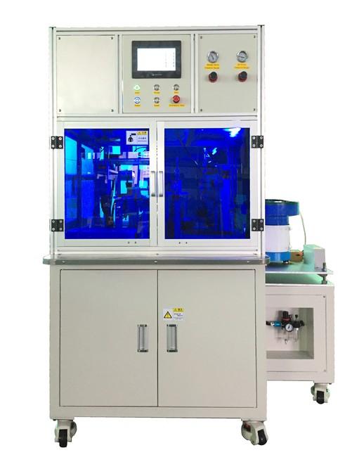
1. Size : L1050mm X W880mm X H1600mm
2. Output: 800-1000PCS/HR ( Depending on capacity of cartridge and oil )
3. Voltage: 3-phase 208V
4. Air Pressure:0.5~0.8Mpa
5. Weight : Around 350KG
Thank you for purchasing Buddy oil filling machine.
*Read this manual thoroughly in order to properly use this machine. Be sure to read “For Your Safety” before you use the machine. It will p rotect you from possible dangers during operation.
*After having read this manual, keep it in a handy place so that you or the operator can refer to it whenever necessary.
1
FOR YOUR SAFETY
Safety Precautions
The precautions stated in this manual are provided for the customer to make the best use of this prod uct safely, and to provide preventive measures against injury to the customer or damage to property.
Be sure to follow the instructions
Various symbols are used in this manual. Please read the following explanations to understand what each symbol stands for.
Symbols indicating the Degree of Damage or Danger
The following symbols indicate the degree of damage or danger which may be incurred if you neglect the safety notes.

Warnings

Cautions
These “Warnings” indicate the possibility of death or serious injury.
These “Cautions” indicate the possibility of accidental injury or dam age to property.
Symbols indicating the type of Danger and Preventive Measures
The following symbols indicate the type of safety measure that should be tak en.


Indicates the type of safety measure that should be taken.
Take care. (General caution)

Indicates prohibition.
Never do this. (general prohibition)
Do not disassemble, modify or repair.
Do not touch. (contact prohibition)

Indicates necessity
Be sure to follow instructions.
Be sure to unplug power supply from wall outlet.
Be sure to check grounding.
2
FOR YOUR SAFETY


Warnings
Be sure to check grounding.
Improper grounding can cause electric shock or fire.
Be sure to use within the voltage range indicated on the unit. Failure to do so may cause electric shock or fire.
Plug the power cord into the wall outlet firmly. Failure to do so can cause the input to heat up and may result in fire. Make sure that the power plug is clean.
Be sure to unplug the power cord from the wall outlet when you e xamine or grease the machine.
Failure to do so may cause electric shock or fire.
Stop operation and unplug immediately whenever you sense any abnormalities, such as a pungent odor. Immediately contact the d ealer from which you purchased the product.
Continued operation may result in electric shock, fire or malfunction.

Install the product in a place which can endure it’s weight and co nditions while running.
Be sure to leave a space greater than 30cm between the back of the equipment and the wall. Installation in an insufficient or unstable place can cause the equipment to fall, overturn, breakdown, or overheat.
Do not attempt to disassemble or modify the core components of the equipment.
Disassembly or modification may cause electric shocks, fire or malfunc tion, no after-sales service will be provided either.
3
FOR YOUR SAFETY


Warnings
Use the machine indoors where no flammable or corrosive gas is p resent.
Emission and accumulation of such gasses could lead to fire.
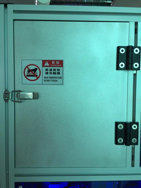
Don’t touch the oil barrel when the equipment is heating.
Failure to do so may result in thermal burns.
Be sure to unplug the power cord from the wall outlet if the equipment will remain unused for long periods of time. Gathered dust could lead to fire.
Be sure to use power in the proper voltage range. Failure to do so may result in fire or malfunction.
Keep the equipment and the power cables away from water and oil. Failure to do so may result in electric shock or fire.
Turn off the equipment before inserting and removing cables. Failure to do so may result in electric shock, fire, or malfunction of the equipment.
Keep the scram (emergency stop )switch within reach of an operat or while running the equipment.
Failure to do so may lead to danger since the equipment cannot be stop ped immediately and safely.
Regularly check that the scram (emergency stop) switch works pro perly.
Failure to do so may lead to danger since the equipment cannot be stop ped immediately and safely.
4
FOR YOUR SAFETY
Cautions

Be sure to check grounding.
Improper grounding may cause malfunction or defect.
Use the Desktop Machine in an environment between 0 to 40 degre es centigrade with a humidity of 20 to 95 percent without condens ation.
Failure to do so may result in malfunction.
Use the machine in an environment where no electric noise is pres ent.
Failure to do so may result in malfunction or defect.
Use the machine in an environment where it is not exposed to dire ct sunlight.
Failure to do so may result in malfunction or defect.
Be sure to confirm that tools such as the electric screwdriver unit, etc. are properly connected.
Failure to do so may result in injury or defect.
Check the mounting screws regularly so that they are always firml y tightened.
Loose screws may cause injury or defect.
Be sure to check the wiring to the main unit. Improper wiring may cause malfunction or defect.
Be sure to secure the movable parts of the equipment before trans portation.
Failure to do so may result in defect or injury.
Do not bump or jar the machine while it is being transported or ins talled.
This can cause defects.
5
CONTENTS 1. Operation Guideline and Preparations 1.1 Work Flow-----------------------------------------------------8 1.2 Machine Placement-------------------------------------------8 1.3 Power and Air Supply-----------------------------------------8 1.4 Manual Switch/ Digital Controller/Fiber Amplifier -----------9-11 1.5 Installing and Testing-----------------------------------------12-15 2. Operation Instruction 2.1 Reset-----------------------------------------------------------16 2.2 Auto Run------------------------------------------------------16 2.3 Start Oiling----------------------------------------------------16 2.4 Cleaning Material ---------------------------------------------17 2.5 Cleaning System-----------------------------------------------17 2.6 Adjustment location for funnel conveyer----------------------18 3. Operation Interface 3.1 Startup picture-------------------------------------------------19 3.2 ①Manual Interface--------------------------------------------20 3.3 ②Manual Interface--------------------------------------------21 3.4 ③Manual Interface--------------------------------------------22 3.5 Oiling Interface------------------------------------------------23 3.6 Temperature Interface-----------------------------------------24 3.7 ④Manual Interface--------------------------------------------25 3.8 ⑤Manual Interface--------------------------------------------26 3.9 ⑥Manual Interface--------------------------------------------27 3.10 Automatic Control--------------------------------------------28 3.11 Parameter Setting-------------------------------------------- -29 3.12 Alarm Screen--------------------------------------------------30 4. Troubleshooting------------------------------------------------31-32 5. Accessories and Spare Parts-----------------------------------33 6. Care and Maintenance-----------------------------------------34 6
1. Operation Guideline and Preparations
1.1 Work Flow
Unpack and Inspection
Machine Working Zone
Power and Air Supply
Installing and Testing
Auto Run and Start Oiling
System Cleaning
7
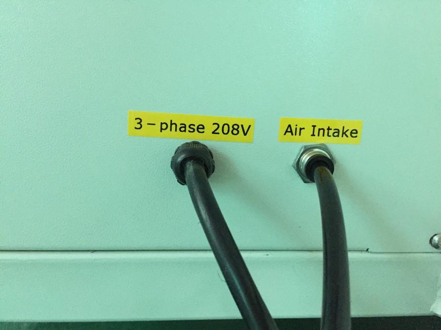
1.3.2 Power 3-phase 208V
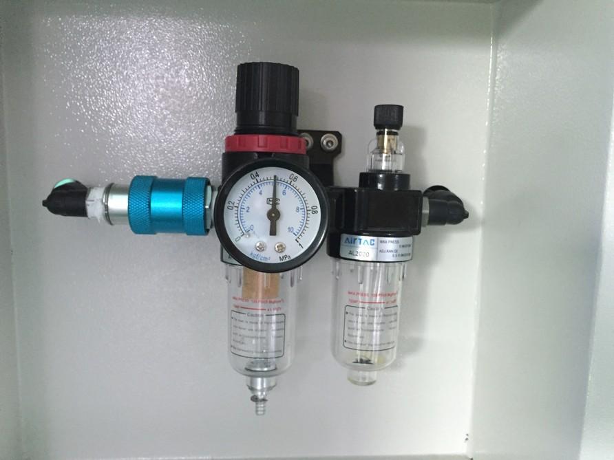
Air Regulator
 1.3 Power and Air Supply
1.3.1 Connect Power cord and Air Pipe
1.3 Power and Air Supply
1.3.1 Connect Power cord and Air Pipe
,
Air
Pressure 0.5-0.8Mpa. Air Valve(blue parts), to the left is to Close, to the right is to Open.
Power Air Intake
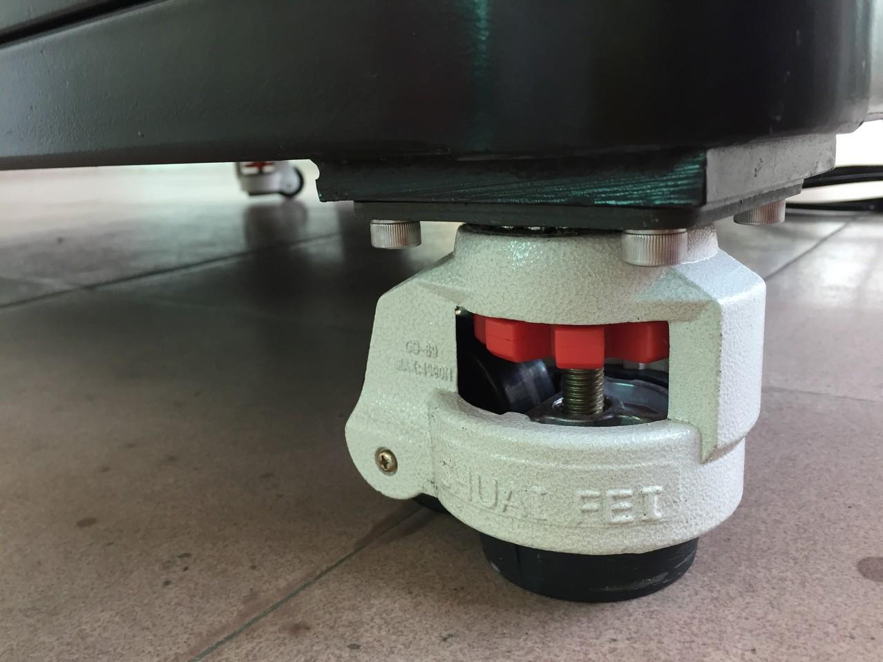
1.2 Machine Placement
Turning red nob upwards to lock machine from movement, Turning downwards to unlock machine for relocation.
Air Valve
8
Pressure Gauge

Adjusting Valve.
Suggested Air Pressure:
Needle Valve: 0.4MPa, Oil Drum: 0.3MPa.
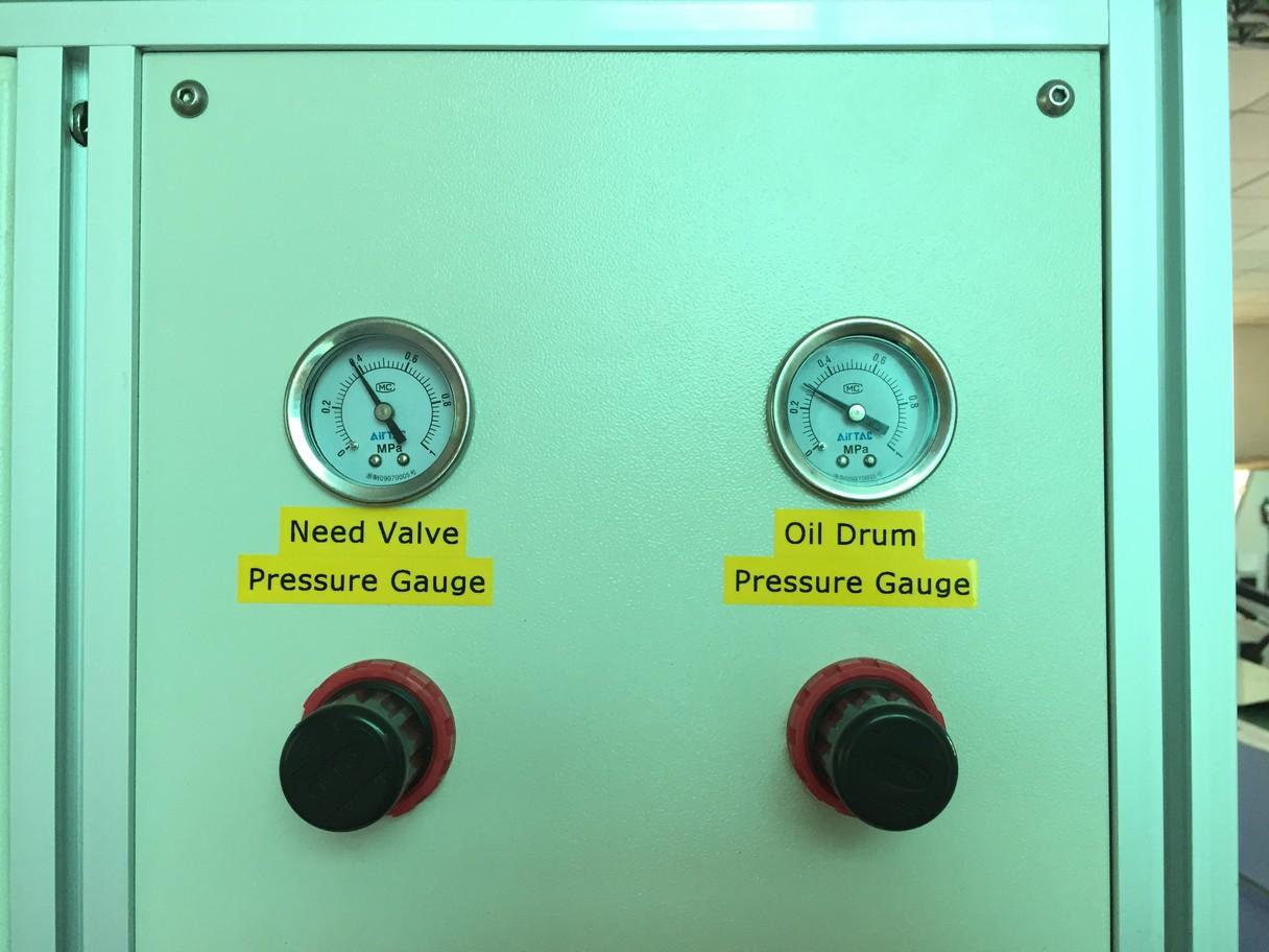
 1.4 Manual Switch
1.4.2 Needle Valve Pressure Gauge, Oil Drum Pressure Gauge, independent
1.4 Manual Switch
1.4.2 Needle Valve Pressure Gauge, Oil Drum Pressure Gauge, independent
9
Adjusting Valve Adjusting Valve
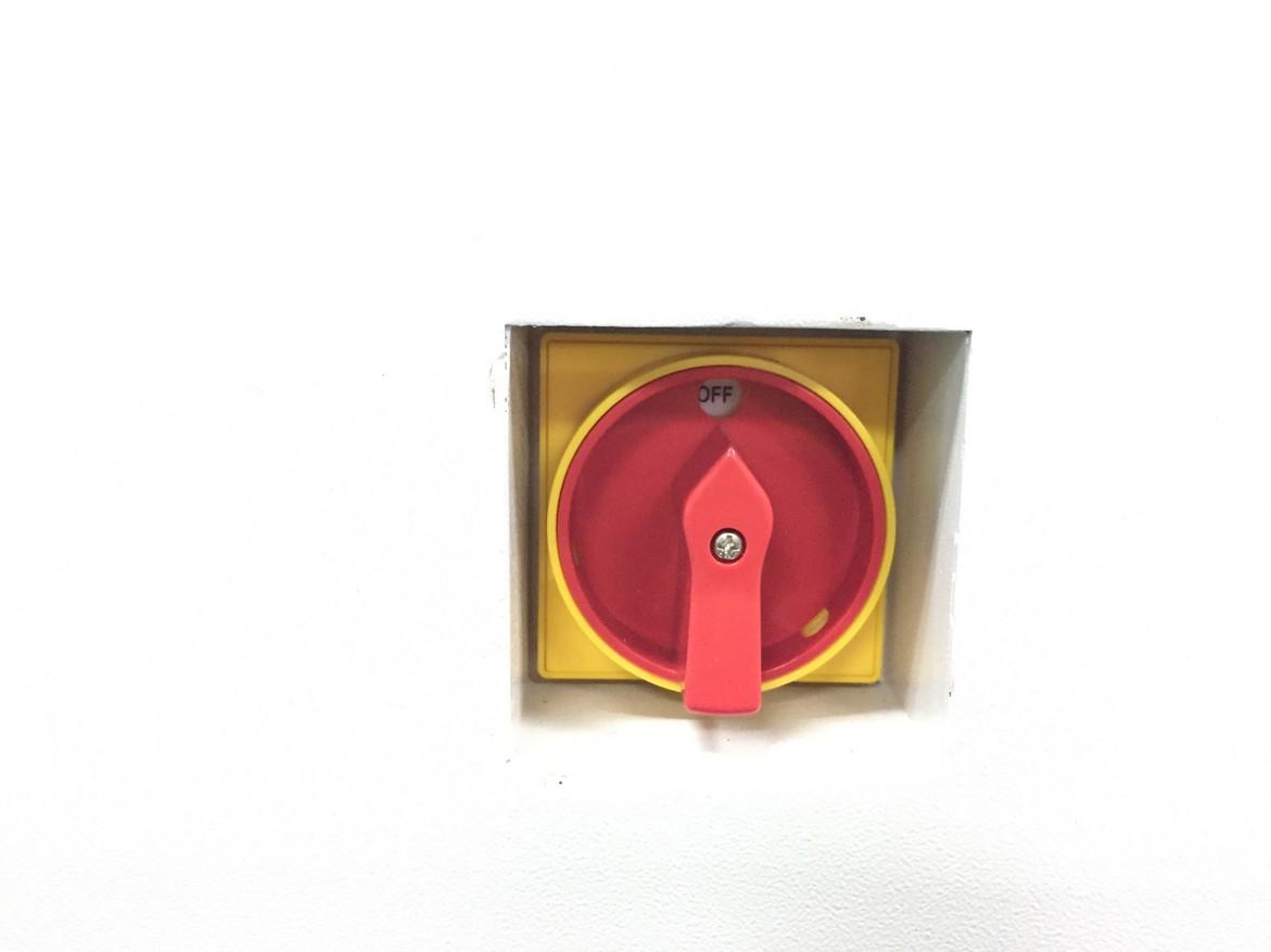
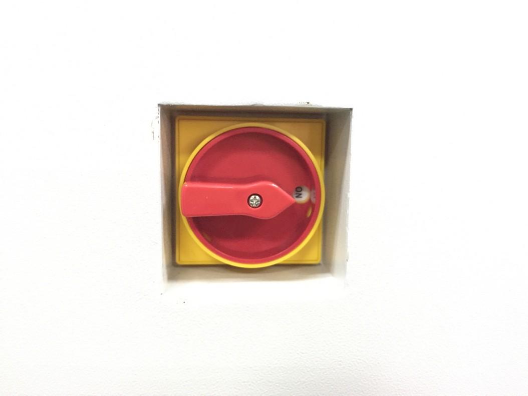
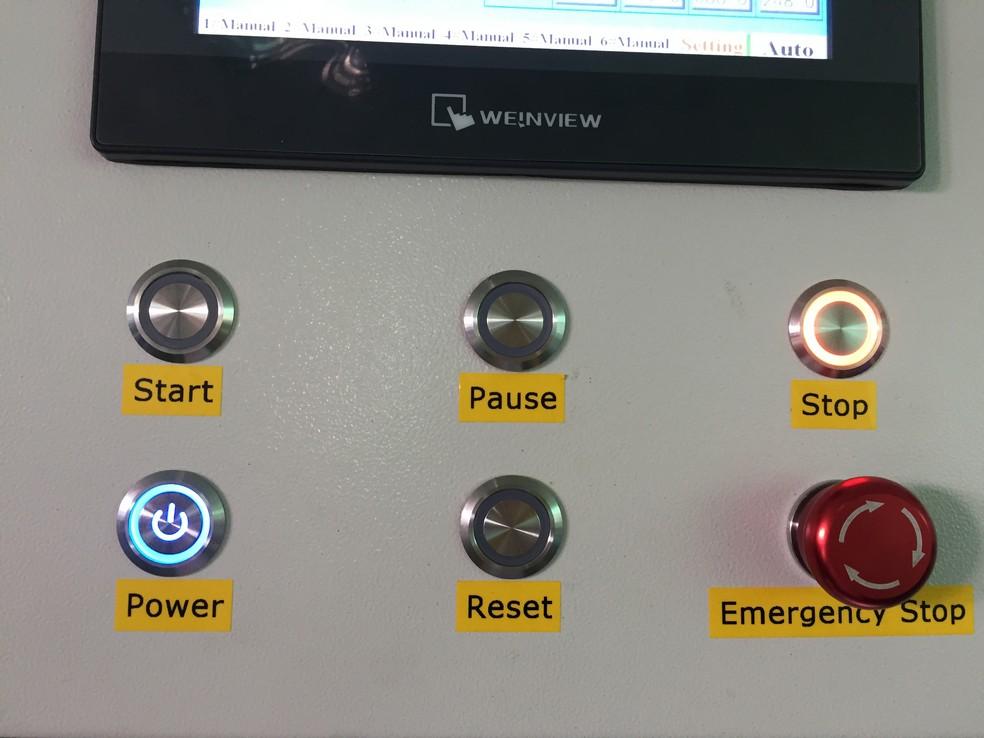
1.4.1 Start, Pause, Stop, Power, Reset, Emergency Stop.
1.4.4 Digital Controller for Vibratory Feeder, to adjust feeding speed by changing Voltage and Frequency, it will be turned on automatically when machine is in running mode. It has been pre-set by factory, normally no need further adjustment.
1.4.5 Fiber Amplifier
Variable Frequency Digital Controller
For Vibratory Feeder
Saturated Accelerate Remote Stop Lock Vol+ Vol-
Frequency ▲
On Delay FUNC
Off Delay ▼
Soft Start
ON/OFF
Fiber Amplifier is to detect and sensor whether material is in position. B is preset from factory, C is current, when Current is bigger than pre-set, D indicates red , material in right location ; No indication, material not in place.
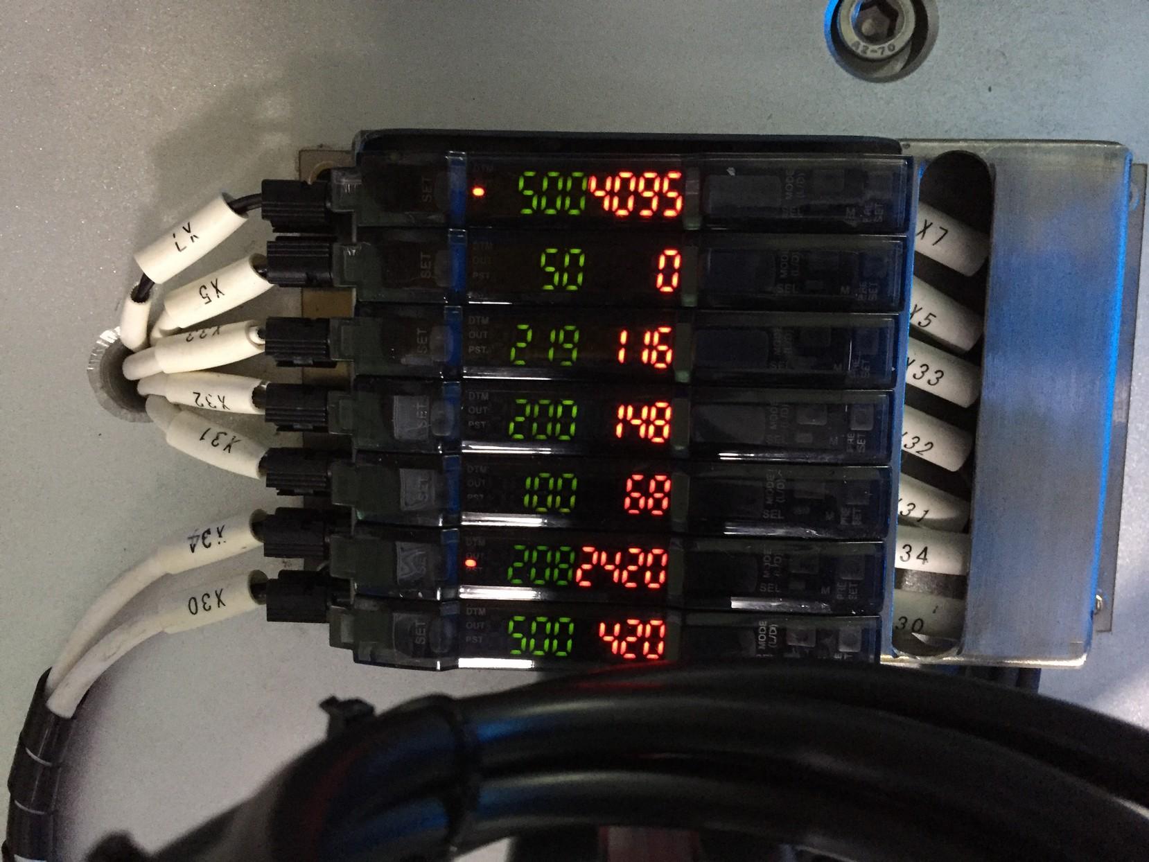
● ● ● ● ●
A B C D 10
For the detailed location and function of sensors see as below.
A-X32 to detect workstation① feeding fixture material.
A-X5 to detect workstation⑤mouth piece material.
A-X7 to detect workstation④mouth piece material.
A-X34 to detect workstation① Vibration material.
⑥ material.
11
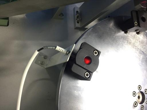
A-X33 to detect workstation①pushing material.
A-X30 to detect workstation① feeding material.
A-31 to detect workstation
1.5 Installation and Testing
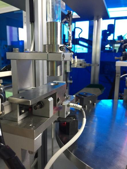
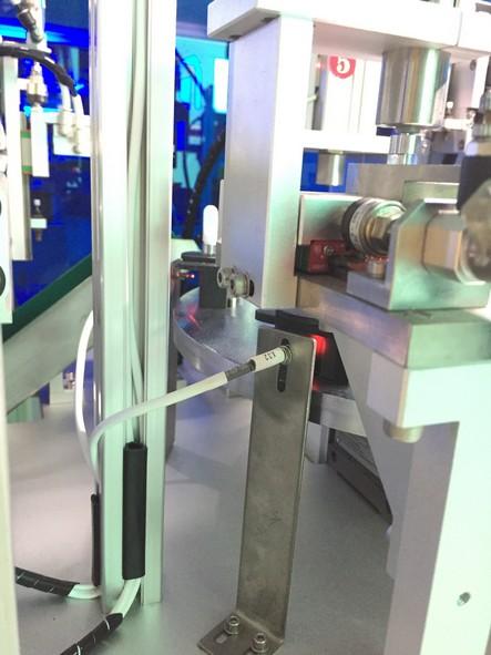
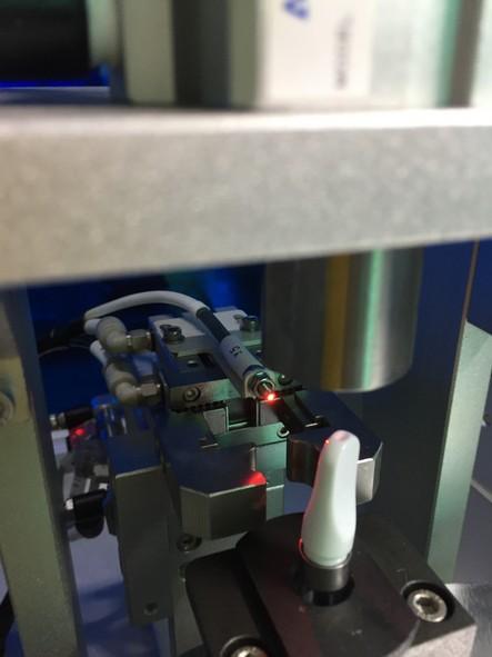
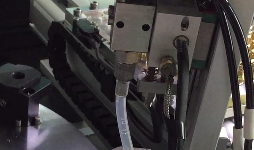
1.5.1 Install Injector
Place injector into holder, tighten screw, must be aligned with bottom location fixture.
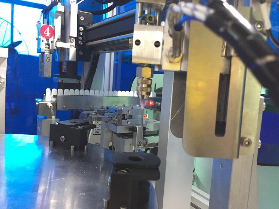
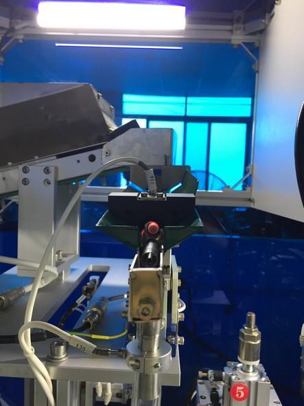
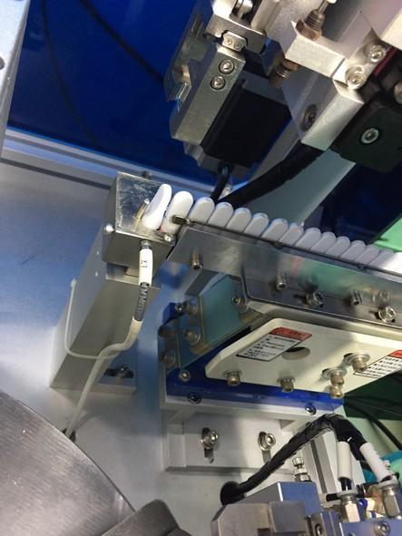
1.5.2 Install vibration
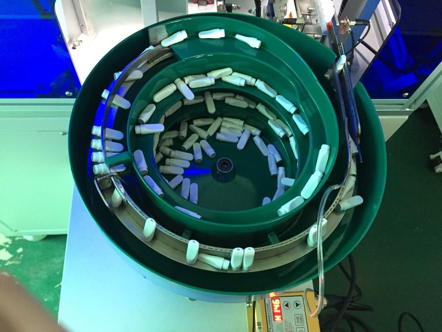
Load mouth piece into the middle of vibration plate. When install vibration plate, please align at joi nt to make sure the mouth piece can go smoothly from vibration plate to workstation.
Keep clean of vibration plate: Wipe dust and other stains on the surface of vibration plate by alcohol and cloth, at regular intervals .
1.5.3 Cartridges Oil container
Load Containers into feeding funnel gently!
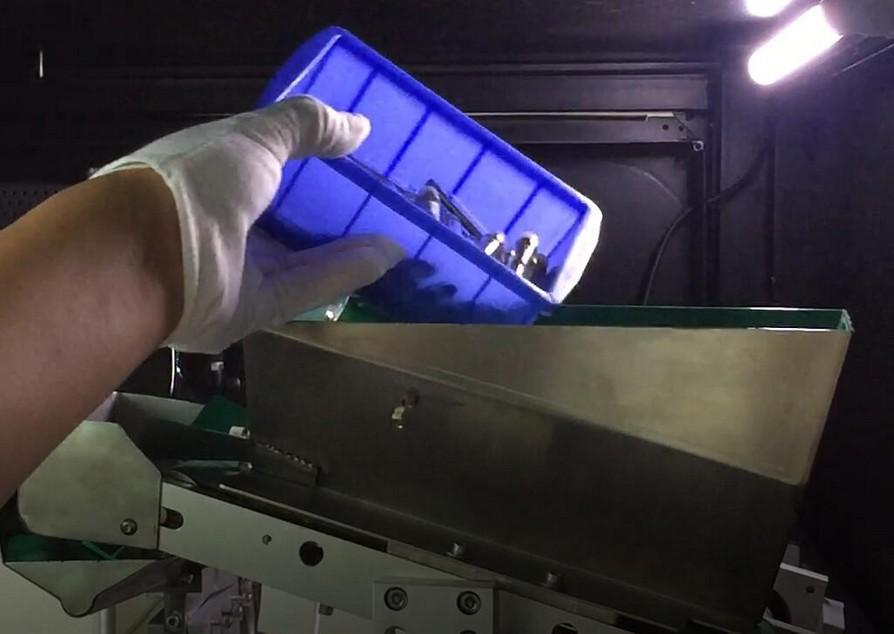 plate and load mouth piece
12
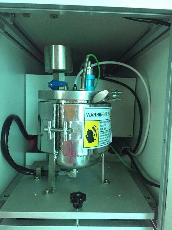
1.5.4 Filling Oil Drum :
Open Drum container , unscrew ① to take Oil drum out for filling. Shut off Air Valve② ,no air should be in at this point, open Pressure Relief Valve④ , pour Oil in at certain amount, capacity 0.3~0.9L , no more than 0.9L !!! Then shut off Pressure Relief Valve④ , turn on Air Valve ② 。 Make sure to follow the above sequence of operation!
Air Valve ② downwards is to open, allow air flow, maintain air pressure in Oil drum. During Oil filling, no air pressure in drum, close Air Valve and open Relief Valve. Note: Fill pre-heated oil to drum if the oil is too thick.

Don’t touch Oil Drum during heating.
1.5.5 Power and Air Supply On.
System will alert for low Oil level, then follow above procedure to fill oil drum.
1.5.6 Check Emergency Stop switch on ( Clockwise )
1.5.7 Click “Setting“enter into ”Parameter Setting“, Click “Auto Heating”. Oil pipe, Oil Pump ,Oil valve and Oil Drum will be heated automatically. Thicker the Oil, Higher the temperature. It may vary depending on the viscosity of oil. After heating for a while, check current temp for Oil pipe, Oil Pump ,Oil valve and Oil Drum, machine could reset and start working only when these temp. achieve Minimum Temp. (How to enter to Setting Interface please refer to Chapter 3.)
1.5.8 Reset
Before resetting the machine, make sure no cartridges in any workstations, and all the temp. achieve Minimum Temp. Press the Reset button for 3 seconds and release, the indicator light flickers, once the indicator light stay in yellow light means reset completed.
③ ①
②
13
④
1.5.9 Purge excess air from tubes before fill Run. Very Important: After reset the machine for the first time, don’t start oiling before eliminate air trip through Oiling system.(Place a small cup or plastic bag under the oil injector to collect the oil)
1.5.9.1 Close Air Valve, open Air relief Valve in the oil drum.
1.5.9.2 Select “Parameter Setting“, click ”Clean“.
1.5.9.3 Press and Hold “Clean“ for 3 seconds , check Injector for air trap until consistent oil flow, press Clean again to stop.
“Clean“ Button also used for System Cleaning Workflow
14
Power On Setting Parameter Setting 1.Empty Oil Drum 2.Parameter Setting 3.Replace Injector with silicon pipe 4.Temperature setup OK Clean
1.5.10 Setting Oil Ration and Oiling Test
After purging air, Reset the machine again. Press “Setting”, enter “Parameter Setting” .
1.5.10.1 Oiling Ration
“Oiling Ration” , to adjust oil volume per each injection, the greater number is, the more oil volume. Max.14mm!!! 1mm=0.08ml Oil, it may vary based on oil viscosity. Once Oiling Ration set, place a cartridge into fixture of workstation② , press Turnplate Rotation, the fixture will rotate to workstation③, press “Oiling Test” , Injection starts at workstation③ , press Turnplate Rotation again, take the cartridge out from workstation④ , please verify Oil Volume until getting the required volume.
1.5.10.2 Oiling Speed (How to enter into Oiling interface, Details to refer chapter 3) In Oiling Interface, both Oiling Ration ① and filling speed can be adjusted.”Guide Motor“Auto Speed②and “Oiling Motor”Auto Speed③, higher the number, faster the filling. Don’t suggest to change factory setting unless it is necessary.
15 ① ② ③
2. Operation Instruction
2.1 Reset the machine ( Note : No materials should be in any one of 6 stations before Reset, all temperature must achieve to Minimum value) light on top of machine stays on yellow after resetting.
2.2 Click Auto, click Manual then indicates Auto, the machine will run in Auto Mode. The atomizers will go down from the hopper to the delivery pipe, until the feed delivery pipe in workstation① is full of atomizers, you can run filling oil.
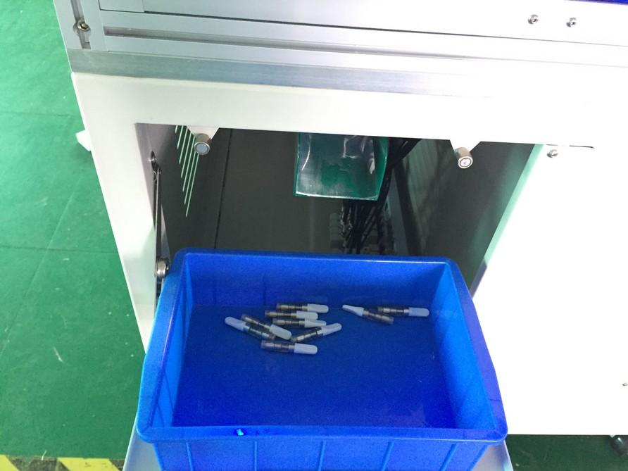
2.3 Press Start button, machine runs oiling. The completed filled cartridges will come out from the following outlet. Please use a soft container to place these filled cartridges, in case scratched or bruised . And take out the filled cartridges every once in a while. After production, turn the Power off
16
2.4 Cleaning Material
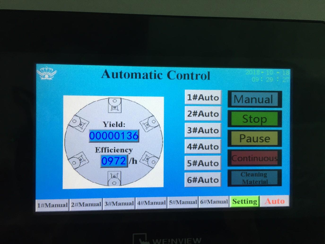
Once working cycle completed, select Automatic Control Mode, click Cleaning Material, 6 workstations are being emptied, in order to Reset machine for next cycle.

2.5 Cleaning Oil Pipe and Oil Drum
Replace injector with silicon pipe, other end connects to disposable tank, fill oil drum with warm water at 140~158℉, close air relief valve, open sliding valve for cleaning cycle. When cleaning completed, no more flowing water from silicon pipe, close sliding valve, open air relief valve, fill with water continue cleaning until cleaned, put back injector for next operation.
17
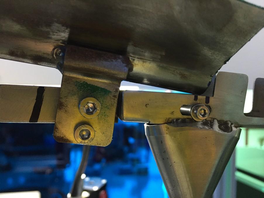
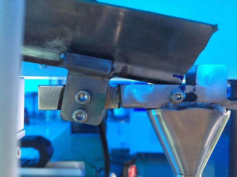
2.6 Adjustment location for funnel conveyer
For 1.0ml and 0.5ml cartridges, location for funnel conveyer is a little different. A operation video will be provided to show how to install.
18
For 0.5ml cartridges
For 1.0ml cartridges
3.Operation Interface
3.1 Startup picture
Turn on the power switch to display startup picture.
Click screen anywhere to enter Automatic Control interface .
Click into 1#,2#,3#,4#,5#,6#Manual interface, system requires Password, factory default PW is 111111, then Enter.


Indicator light on the top
Green: normal operations
Red : abnormal conditio n
Yellow : after reset condition
19
3.2 ① Manual Interface
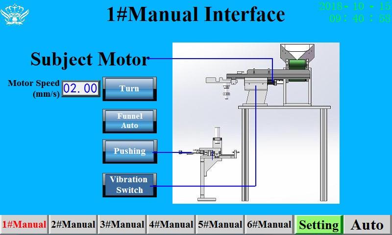
Motor Speed
Turn
Funnel Auto
Pushing
Vibration Switch
Feeder Motor speed
Feeder Motor Rotation
Sensor automatic control for feeder motor and vibration
Pushing Cylinder Forward and backward
Vibration Switch
20
3.3 ② Manual Interface
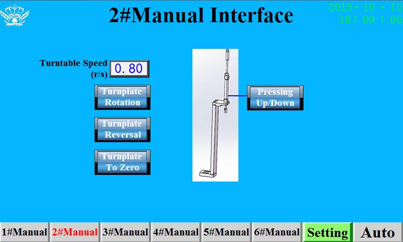
Turntable Speed
Turnplate Rotation
Turnplate Reversal
Turnplate To Zero
Pressing Up/Down
Turntable Speed
Turn plate, counter clockwise one step
Turn plate, clockwise one step
Turn plate back to Origin
Pressing cylinder up/down
21
3.4 ③ Manual Interface
UP/Down
To Zero
Current Position
To Oiling Position
To Safe Position
Following
Oiling Valve Up/Down
Back to Origin
Current Position
Oiling Position
Injector move to the safe position waiting for next oiling
Injector move with the oil level
22
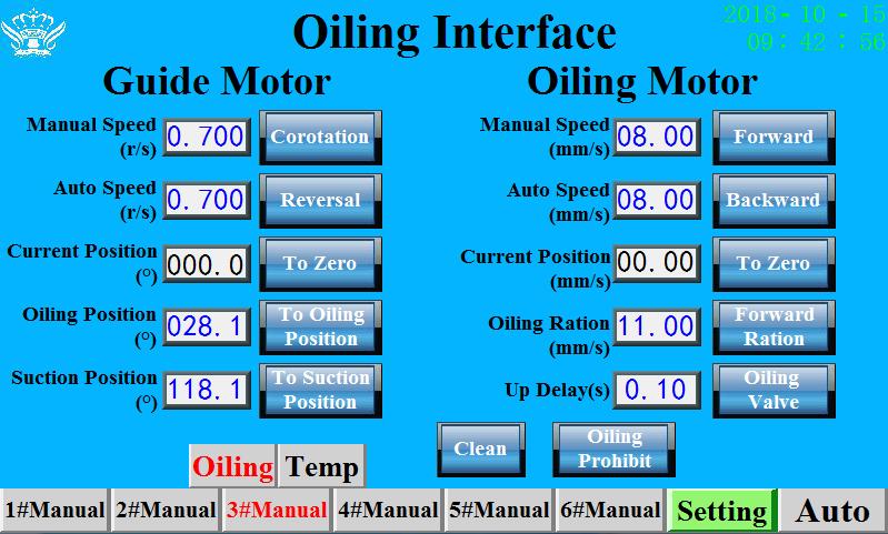
Corotation
Reversal
To Zero (Guide Motor)
To Oiling Position
To Suction Position
Forward
Backward
To Zero ( Oiling Motor )
Forward Ration
Oiling Valve
Clean
Oiling Prohibit
Guide Motor Manual speed, clockwise
Guide Motor Manual speed, counter clockwise
Guide Motor back to Origin
Guide Motor auto speed to injection position
Guide Motor auto speed to inhalation Position
Oiling Motor manual speed forward
Oiling Motor manual speed backward
Oiling Motor back to Origin
Oiling motor movement to control amount of Oil , Max.14mm
Open to inject, Close to Stop
System Cleaning or eliminate air
No injection, machine adjustment only
3.5 Oiling Interface
23
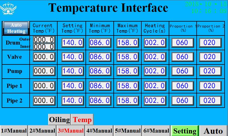
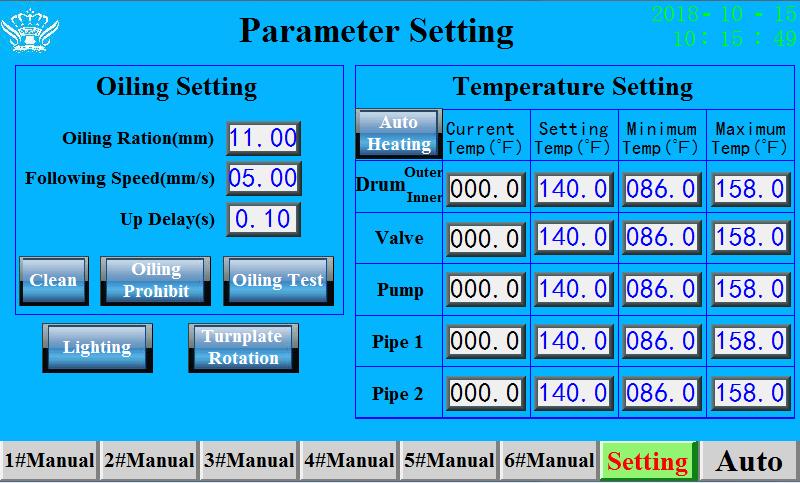
Current Temp (℉)
Setting Temp (℉)
Minimum Temp (℉)
Maximum Temp (℉)
Auto Heating
Current temp of outer drum, inner drum, oil valve, oil pump, oil pipe 1 and oil pipe 2
Setting temp of outer drum, inner drum, oil valve, oil pump, oil pipe 1 and oil pipe 2
Minimum temp of outer drum, inner drum, oil valve, oil pump, oil pipe 1 and oil pipe 2
Maximum temp of outer drum, inner drum, oil valve, oil pump, oil pipe 1 and oil pipe 2
Oil drum, oil valve, oil pump and oil pipe all heat at the same time.
3.6 Temperature Interface
24
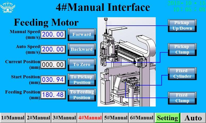
Manual Speed
Auto Speed
Current Position
Start Position
Feeding Position
Forward
Backward
To Zero
To Pickup Position
To Feeding Position
Pickup Up/Down
Pickup Clamp
Fixed Cylinder
Fixed Clamp
Feeding Motor Manual Speed
Feeding Motor Auto Speed
Feeding Motor Current Position
Feeding Motor Start Position
Feeding Motor Feeding Position
Feeding motor manual speed to “ +” direction
Feeding motor manual speed to “ -” direction
Feeding Motor back to Origin
Feeding Motor to pickup position
Feeding Motor to install position
Feeding cylinder up/down
Feeding clamp open/close
Fixed Cylinder
Fixed Clamp
3.7
Interface
④ Manual
25
3.8 ⑤ Manual Interface
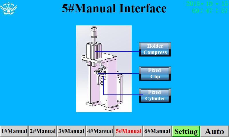
Holder Compress
Fixed Clip
Fixed Cylinder
Holder Compress Cylinder
Fixed Clip
Fixed cylinder forward/backward
26
3.9 ⑥ Manual Interface
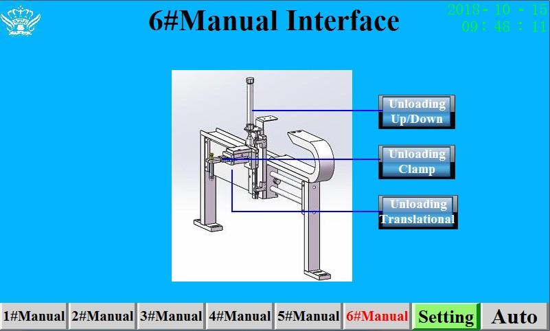
Unloading Up/Down
Unloading Clamp
Unloading Translational
Unloading Up/Down Cylinder
Unloading Clamp
Unloading Cylinder move left/right
27
Manual/Auto Manual and Auto Mode Switching
Stop/Running Stop and Running Mode Switching
Pause
Continuous/Single Step
6 indicator
Pause for temporary stop
Machine test in Continuous mode to complete whole cycle; Machine test in Single step for each station.
6 indicator for material readiness of each station
1-6#Auto Red means normal, Black means stop or complete
Cleaning Material
Page 17
3.10 Automatic Control Yield Output QTY
Efficiency Hourly Output
28
Clean Page 14
Oiling Prohibit No Oiling, machine test only
Oiling Test Test the oiling amount of Oil
Auto Heating Oil Drum, oil valve, oil pump and oil pipe Auto Heating at the same time
3.11 Parameter Setting
29
3.12 Alarm Screen
Show fault and timing occurred.

30
4. Troubleshooting
Failures Solution
Stopping Overtime
Cleaning Subject Overtime
Resetting Overtime
1#Overtime
2#Overtime
3#Overtime
4#Overtime
5#Overtime
6#Overtime
Check whether the cylinder is abnormal, the sensor is normal, workstation complete working.
Check whether the cylinder is abnormal, the sensor is normal, workstation complete working.
Check whether the cylinder is abnormal, X31,X32
Check #1 Cylinder, X32,X33,X30,X34 sensor
Check #2 Cylinder
Check #3 oiling up/down motor, oiling pump and Temp.
Check #4 Cylinder, X7 sensor, feeding motor
Check #5 Cylinder, X5 sensor
Check #6 Cylinder, X31 sensor
X33 Gauging Abnormal(1#Station) Check #1 Cylinder, X33 sensor
Pushing Cylinder Gauging Abnormal(1#Station)
Press Cylinder Gauging Abnormal(2#Station)
Holder Pickup Up/Down Cylinder Gauging Abnormal(4#Station)
Press Holder Cylinder Gauging Abnormal(5#Station)
Holder Fixed Cylinder Gauging Abnormal(#5Station)
Unloading Up/Down Cylinder Gauging Abnormal(6#Station)
Holder Fixed Cylinder Gauging Abnormal(4#Station)
Oil Drum Low Level Alarm(Oiling Station)
1.Check Cylinder
2.Check Sensor
3.Check I/O
4. Check Solenoid Valve
Not enough Oil, fill oil into the barrel.
31
4. Troubleshooting
Failures Solution
Holder Lose(6#Station) Take out the cartridge
X7Gauging Abnormal(4#Station) Check mouth piece material is in position
X30 Gauging Abnormal(1#Station) Check #1 , no material
X31 Gauging Abnormal(6#Station) Check #6, X31 sensor, material still in fixture and in position
Oiling UP/DOWN Motor Alarm(3#Station)
Turn plate Overtime
Holder Feeding Motor Overtime(4#Station)
Oiling UP/DOWN Motor Overtime(3#Station)
Guide Motor Overtime(Oiling Station)
Oiling Motor Overtime(Oiling Station)
Subject Motor Overtime(1#Station)
Check Speed Setup
X32 Gauging Abnormal(1#Station) Check X32 sensor, material still in fixture and in position
Running With Null
No material/ Testing
Oil Drum Temperature Alarm(Oiling Station) Oil Drum Temp. abnormal
32
5. Accessories and Spare Parts
Injector (20g)
Phillips Screw Driver
Screw Driver
Allan Wrench 1set
Fixed Wrench 2pcs
Silicone Cleaning Pipe 1pc
6. Care and Maintenance
6.1 Keep unit clean after each production.
6.2 Check the rails regularly for lubricant.
6.3 When unit is not in use, clean all pipes, and turn off power supply and air source.
Spare Part QTY
5pcs
1pc
1pc
33
