2 minute read
Use a mechanical loader to calibrate the tool and then use hand testing to verify calibration
Calibration
TORQUE TOOL CALIBRATION Tips & Techniques
Advertisement
Annual tool certification with “As Found” and “As Left” results is a bare minimum for quality control. Assembly operations should consider a verification program in addition to annual certification. The verification program should take into consideration the number of cycles the tools perform on a monthly, weekly, or daily basis.
Seven things to remember about torque tool calibration: 1. Remember the difference between Indicated Value (I.V.) and Full Scale Value (FSV) for testing and tool use. Indicated Value readings maintain the same level of accuracy up and down the tool capacity. Full Scale Value maintains that level of accuracy only at tool full capacity. Moving down the tool capacity scale accuracy decreases. A tool with +/- 4% FSV at capacity has a +/- 8% accuracy at 50% of tool capacity. That accuracy continues to decrease as the tool is used at lower capacity levels. 2. Use a torque tester that has a minimum tester to tool ratio of 4:1 accuracy. If your tool is +/- 1% I.V. the tester used to calibrate that tool must be at least +/- .25% I.V. 3. Use a mechanical loader to calibrate the tool and then use hand testing to verify calibration. 4. When starting the day be sure to warm up the tester by testing a wrench five times before beginning to take readings. 5. If a tool has been unused for a day or more, be sure to exercise the tool at least three times prior to testing. The spring and lubricants can “settle.” When this happens the first few readings may not accurately represent tool condition. 6. Testing cycles should be based on activity, not time frames. If you can’t track activity, then use time frames as a method of tracking calibration. 7. Tools should be labeled with tool capacity, work station, date of last calibration, next calibration date, and the person responsible for calibration.
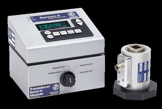
Becoming ISO/IEC 17025 accredited with one calibration station is one thing. Consistently repeating results at twelve stations and remaining within your uncertainty budget is another. No small detail can be over looked. To eliminate the effect of side-loads, we designed our transducers to have bearings to support the working end. From 1 inch pound to 600 foot pounds we designed our transducers to have a common mounting footprint. To ensure +/- .25% indicated value accuracy, our System 8 instrument stores a 20-point calibration table for each transducer.
Whether you are testing tools in the lab or on the plant floor, our System 8 and TorqTronics 2 are designed to test most, if not all common, assembly tools. This includes torque controlled power tools. Both of these testers come with our “Fail Safe Engineering” protocol that notifies the operator when the transducer has been stretched beyond 120% of its rated capacity.


