Professional
2018-2024
May Wang
Work
712 Seward
Project Description
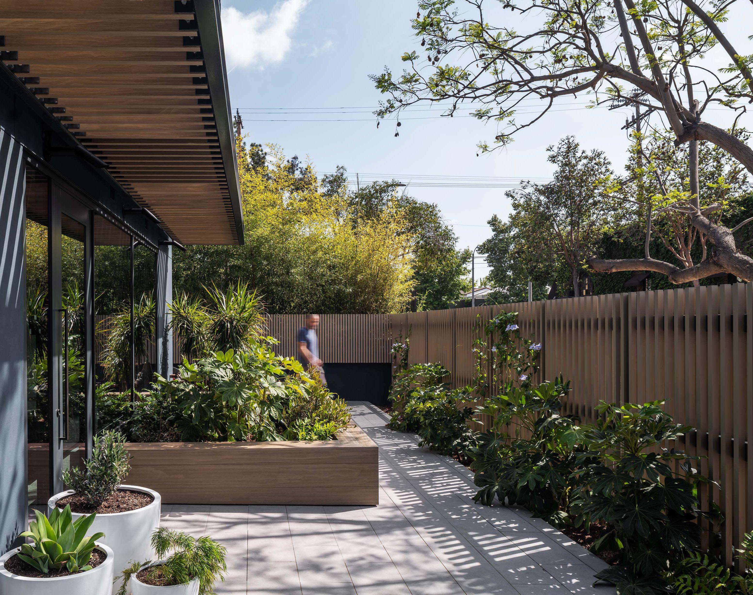
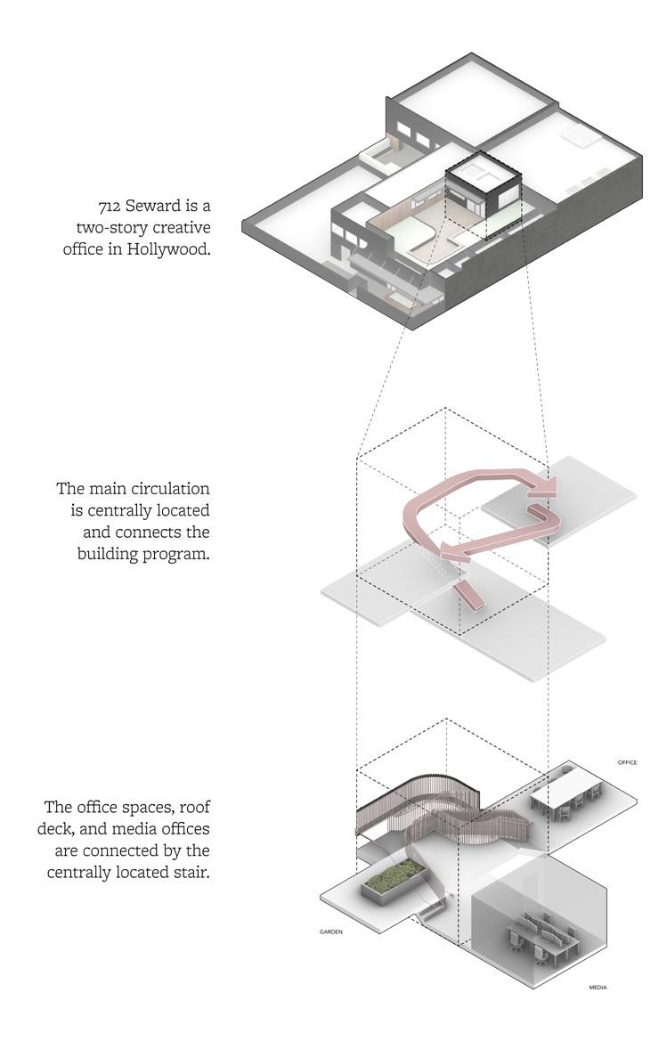
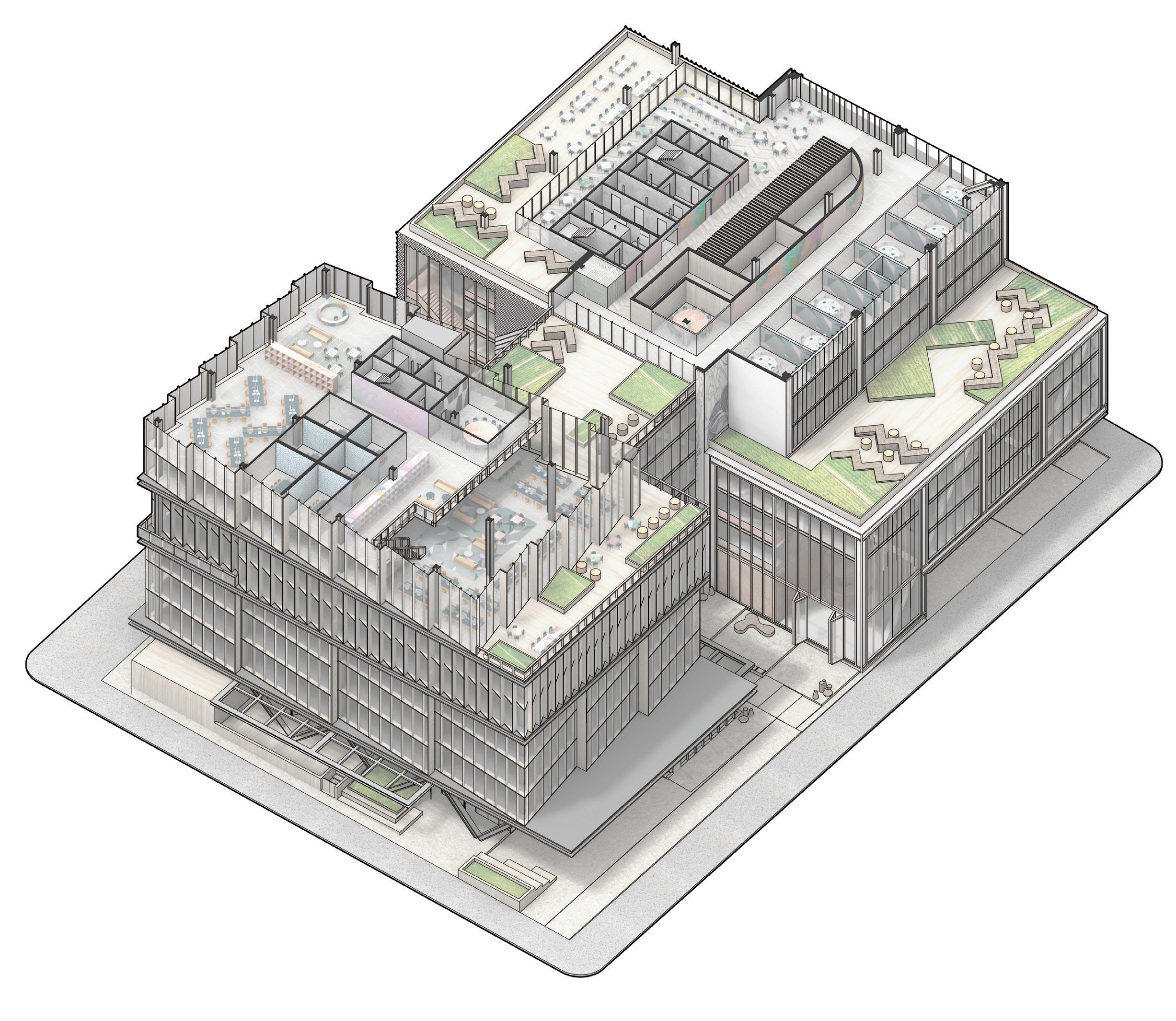
712 Seward is an adaptive reuse project of an existing 1920s building - the open interior, updated detailing, and straightforward exterior nestled in lush planting builds off the local vernacular to re-figure functional space as comfortable, habitable space.
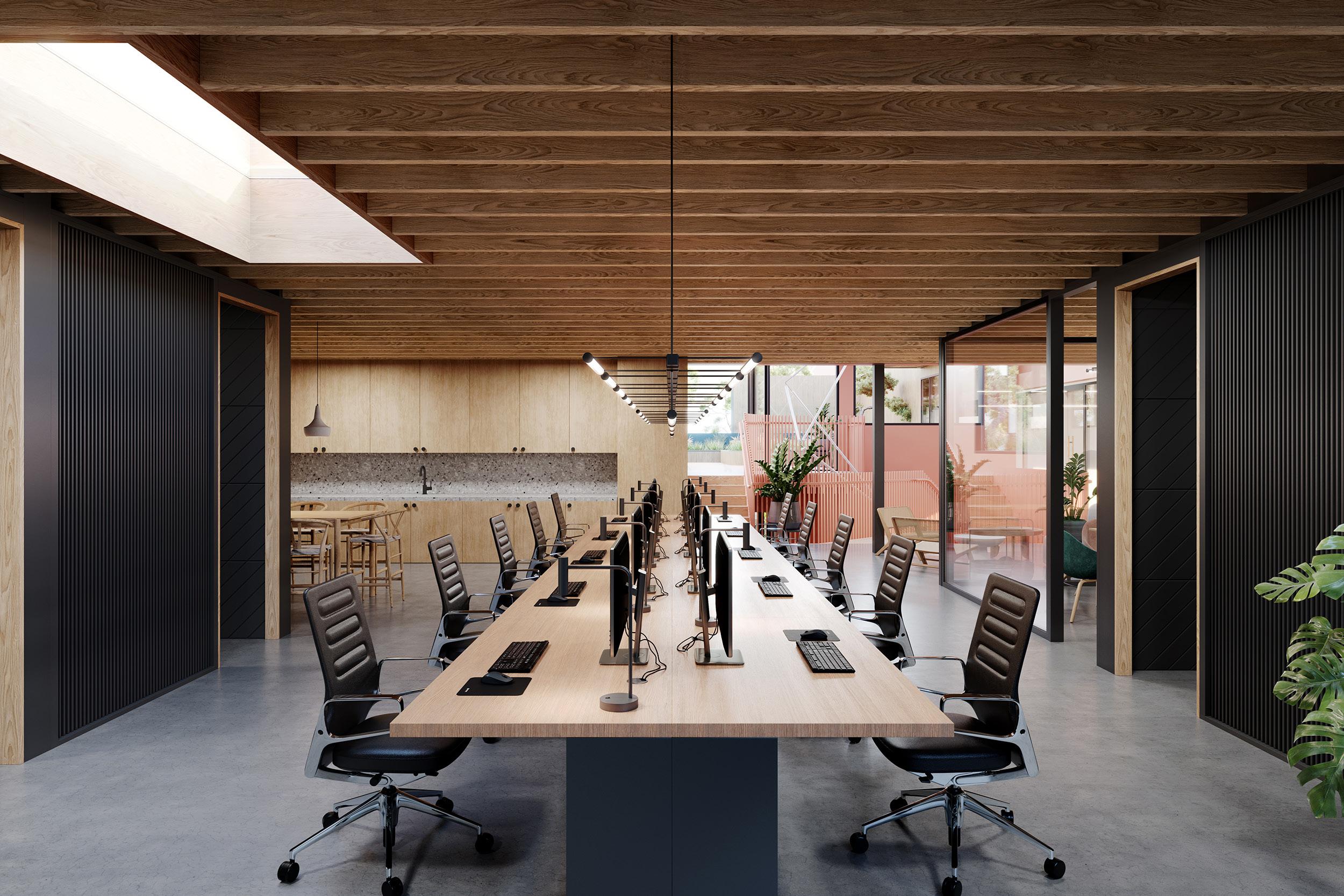
Designed to house post-production and creative tenants in the film industry, the building offers specific areas for editing, screening, and post-production work, while also providing flexible zones for open office and communal activity.
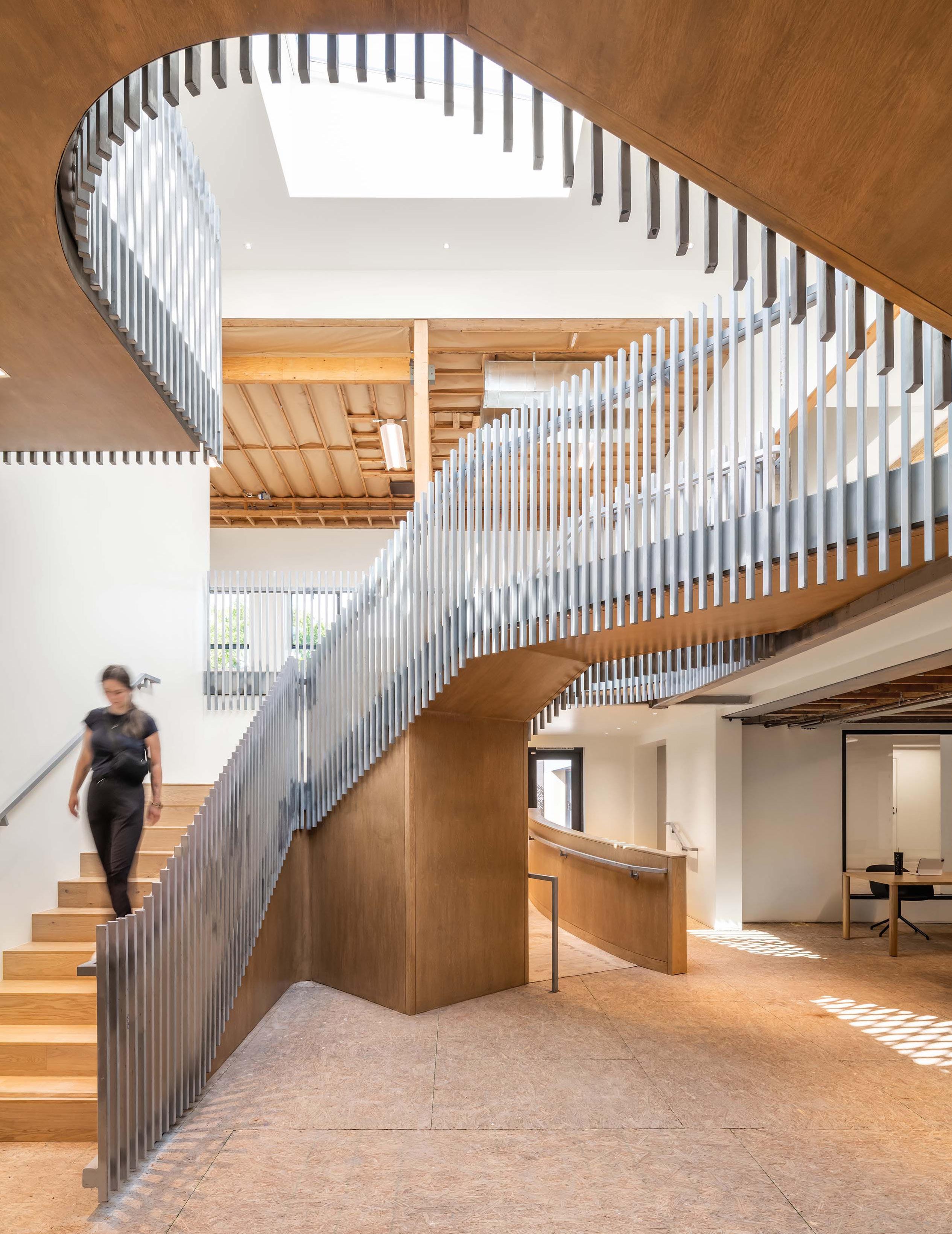
The central atrium and stair make up the node around which the building’s circulation and program are organized. The stair is the social hinge that connects the workspaces, roof gardens, and building services. As it wraps the atrium, the twisting stair defines the space, accentuating the central node and directing movement through the building.
3
Concept Design, SD, CA Otherworks 2021-2022 Hollywood, California Creative Office / Retail 16,000 sqft
Personal Contribution • Interior Space Planning • 3D Modelling • Coordination with third party renderers • Reviewed submittals in CA
5
9514 Towne Centre
Project Description
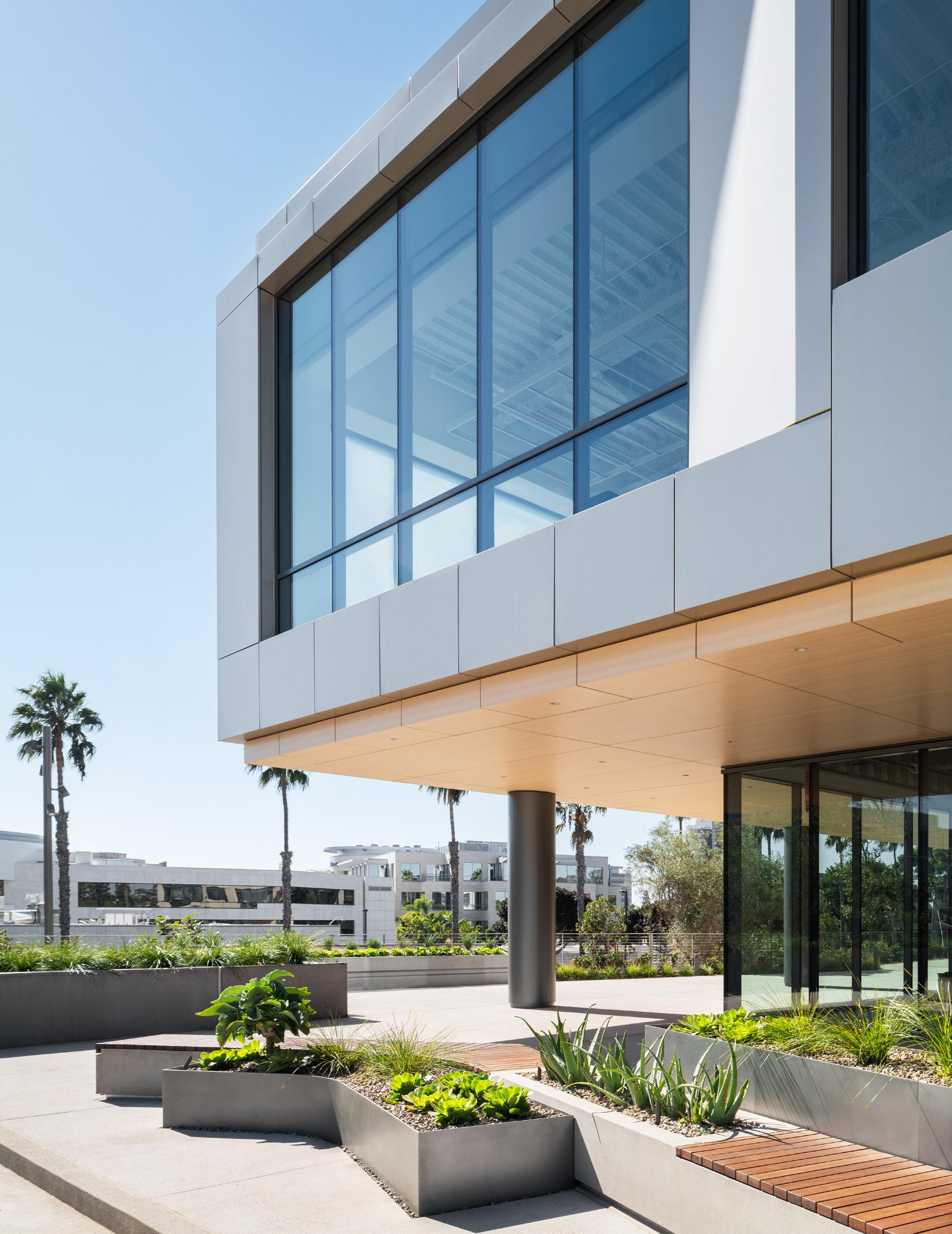
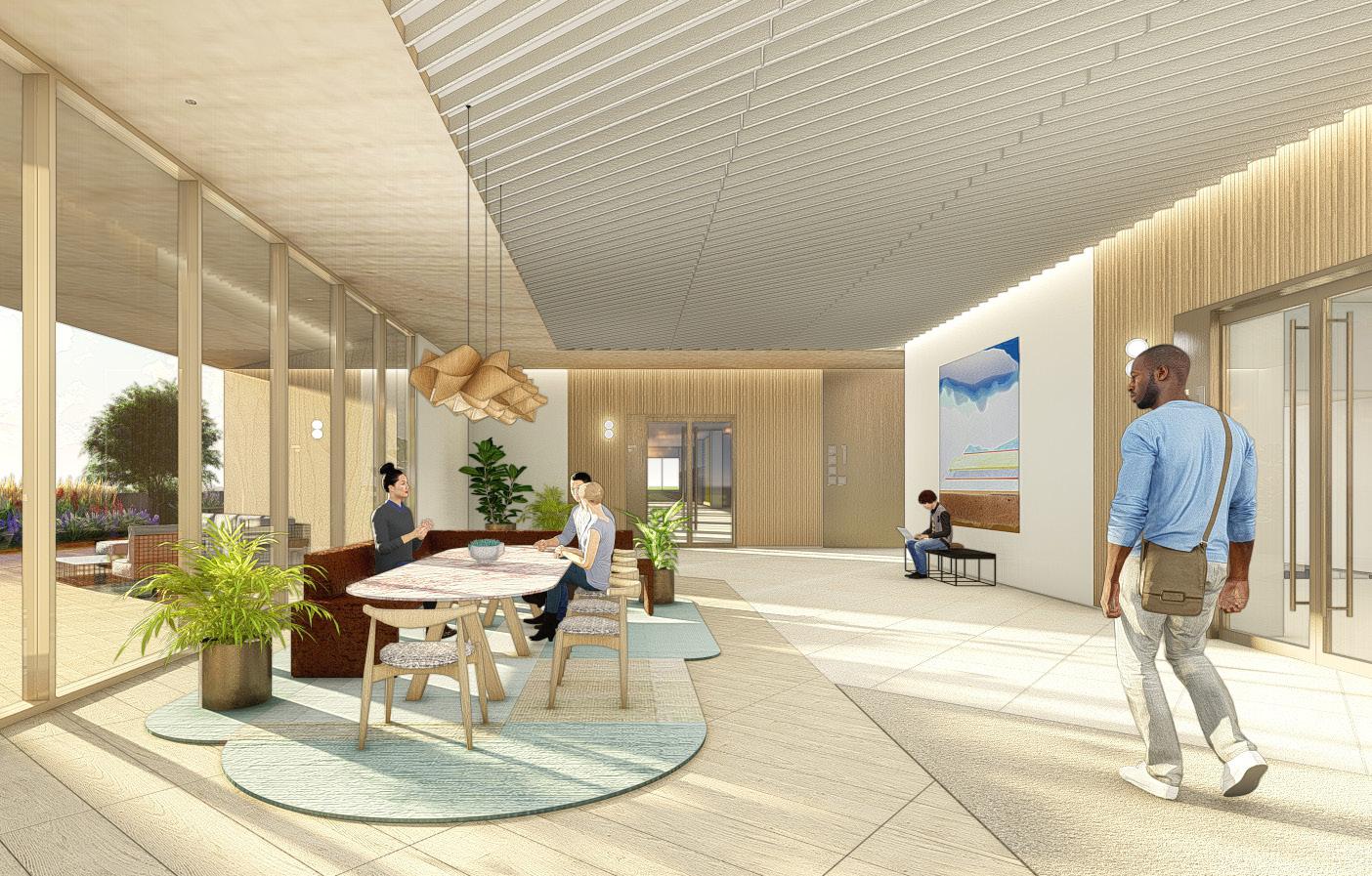
Embedded in San Diego’s landscape, 9514 TCD takes advantage of the site’s existing topography and open space to locate and integrate itself into its surroundings. Designed to support life-science users, the deep landscape buffers and the city’s temperate climate frame attractive amenities that can also support contemporary creative offices.
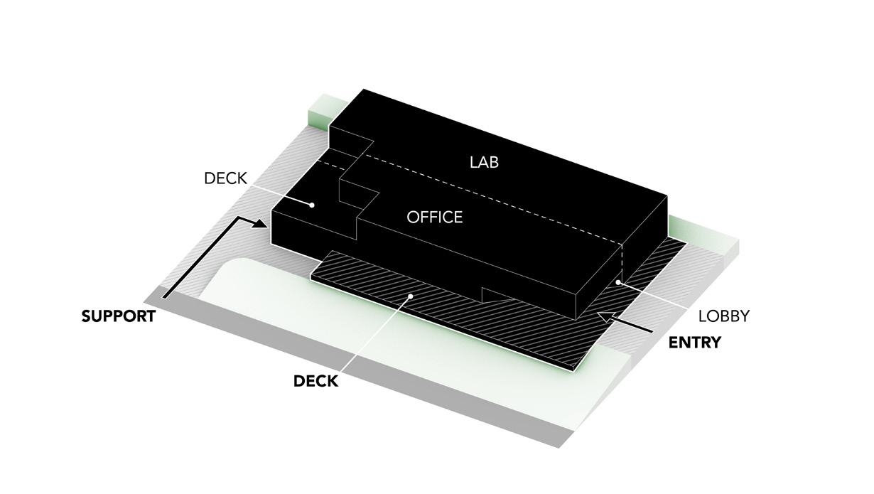
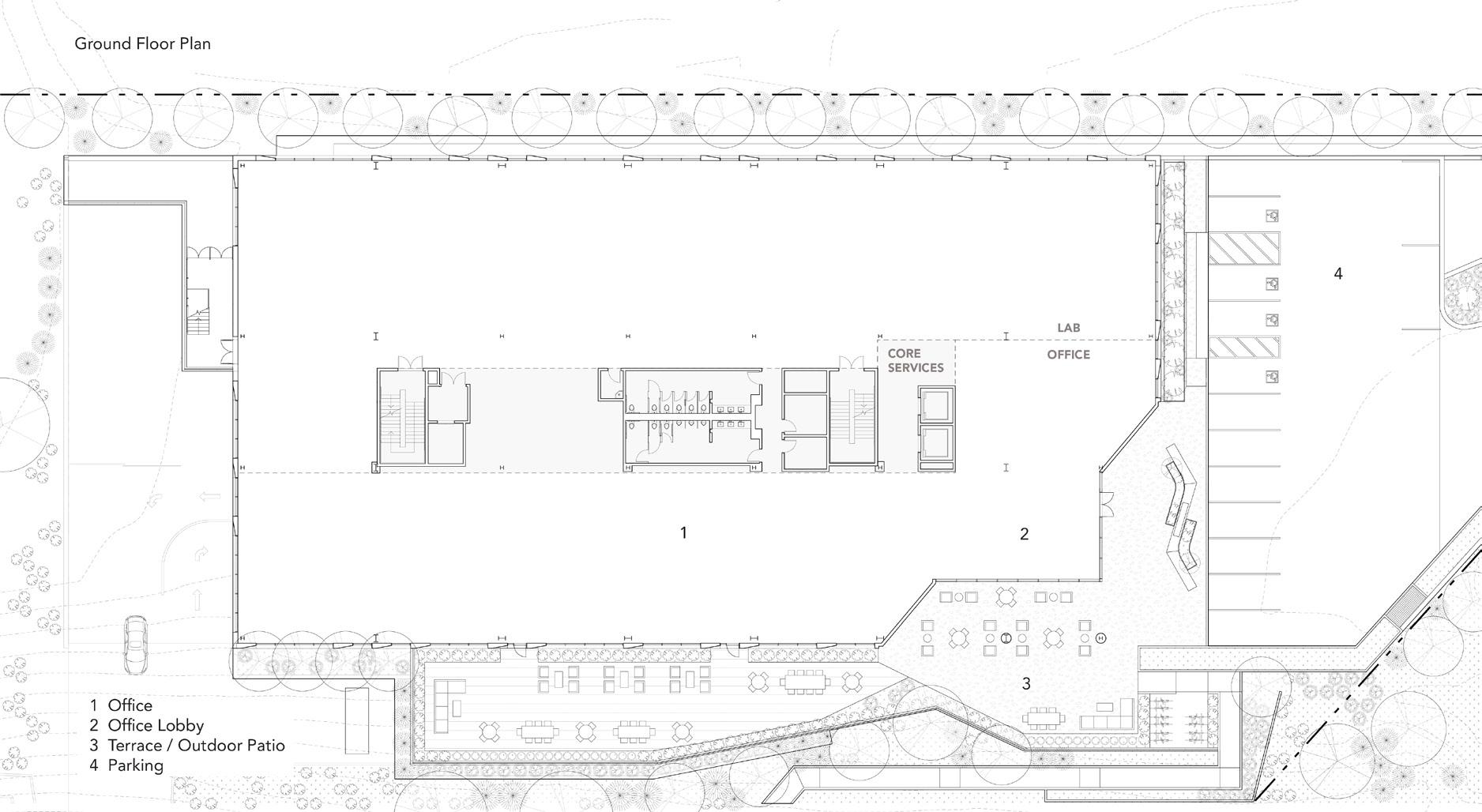
The project is in San Diego’s “Hub of Innovation”, a neighborhood that has earned its name with its extensive science and research community. The two-story building is planned and designed to support laboratory uses through an open and flexible plan with perimeter columns, deep bays, 16-foot floor to floors, and high-load, vibration-resistant floors. The high floors promote tall 12’-0” windows to provide exceptional office daylighting across the deep office bays.
Personal Contribution
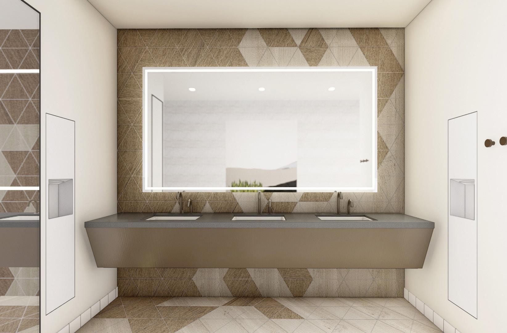
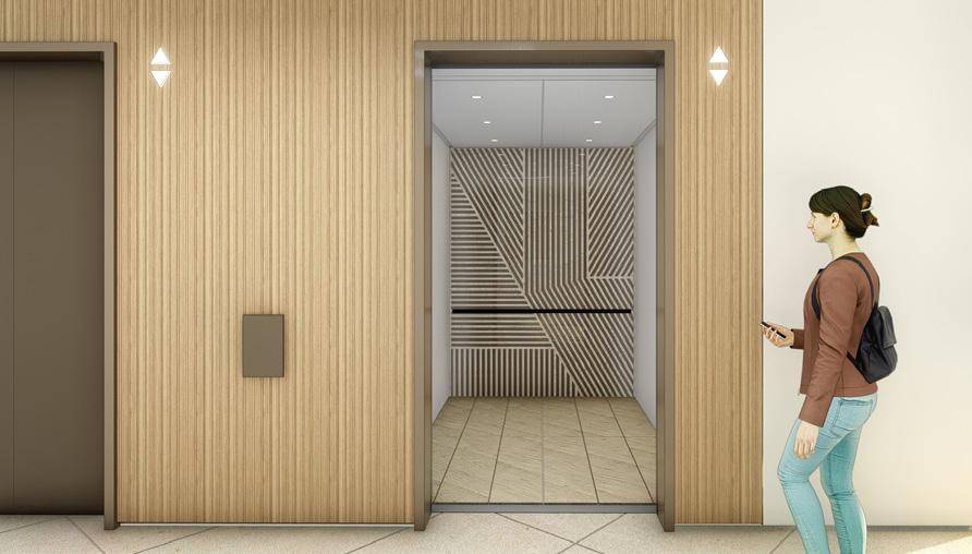
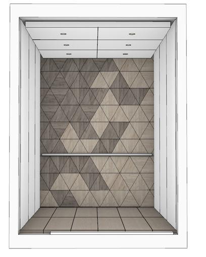
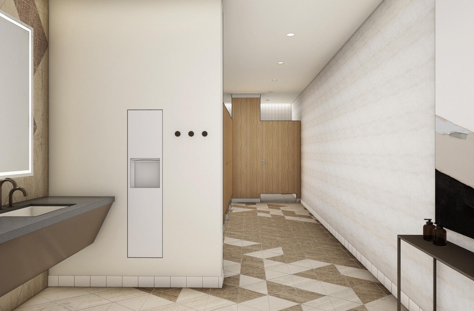
• Lobby and Restroom design
• Produced renderings, plans, and diagrams for regular client presentations
• Selected furniture, finishes, and fixtures for client review
7
SD,DD Otherworks 2020-2021 San Diego, California Lab / Creative Office 52,000 sqft
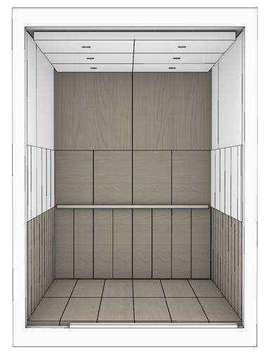
9 May 25, 2021 REV 3 1/4” = 1’-0” 1/4” = 1’-0” 2. LOBBY INTERIOR ELEVATION
LOBBY INTERIOR ELEVATION Page 1/4” = 1’-0” BATHROOM 1. TOP OF ALL MIRRORS AT 8’-0” A.F.F. 2. ALL FIXTURE LOCATIONS TO BE REVIEWED WITH TILE LAYOUT 3. FINISHED CEILING AT 9’-0” A D B C
1.
Undisclosed: Seattle Tower
Project Description
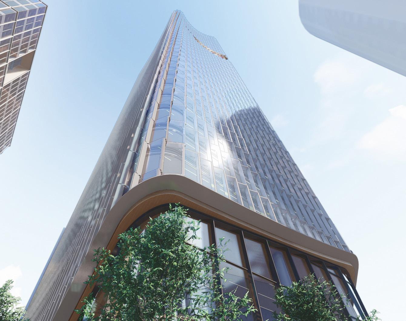
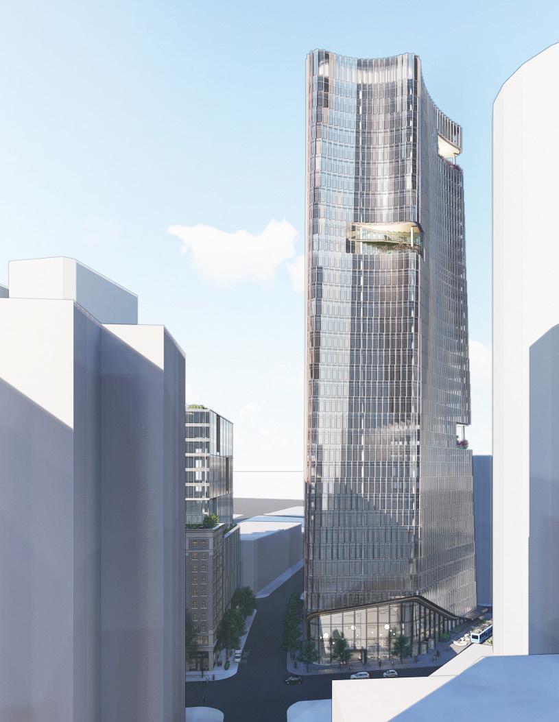
As part of a multi-tower development in downtown Seattle, Otherworks was responsible for the design of a 420’ mixed-use commercial office building facing a public plaza and the terminus of a streetcar rail line.
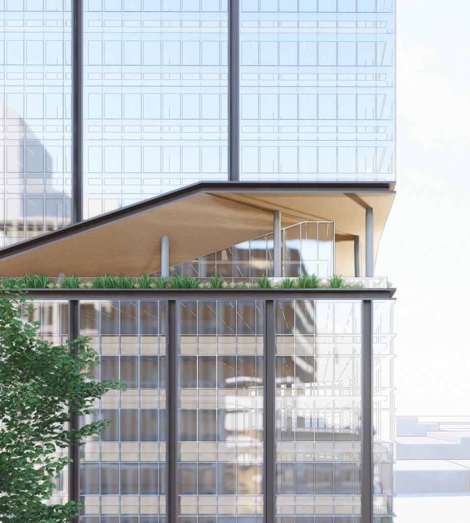
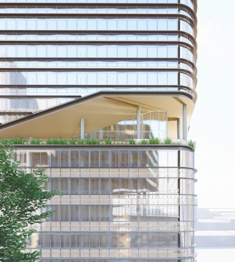
The building’s floorplates reflect the site’s unique trapezoidal shape, and the building facade scallops inward as the tower approaches the top of its 420’ height. Multi-level decks are created by cutting through strategically located corners of the tower to allow expansive views across the city.
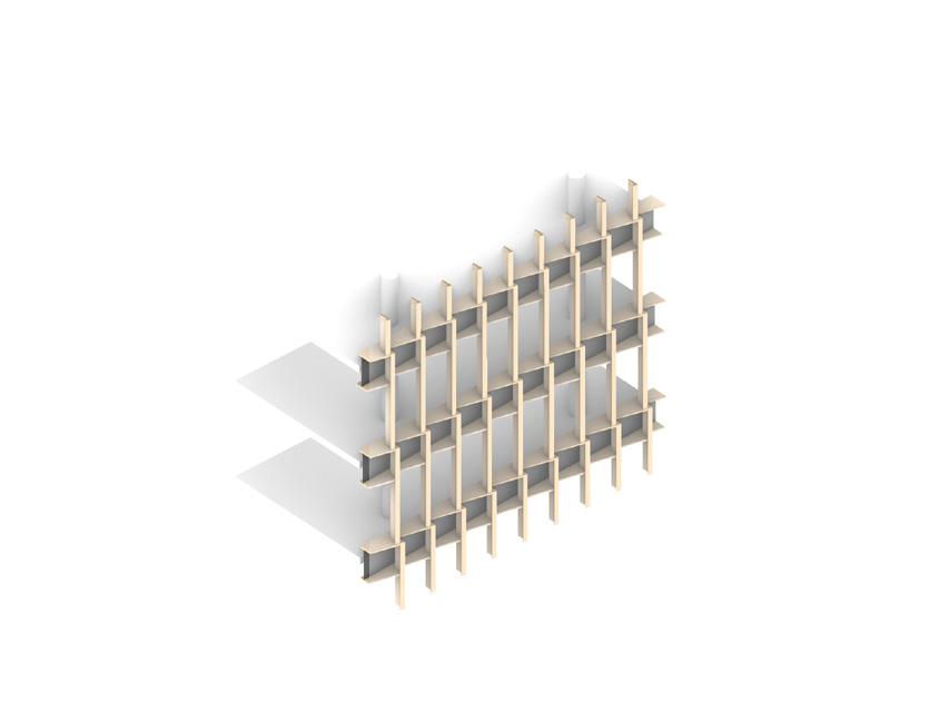
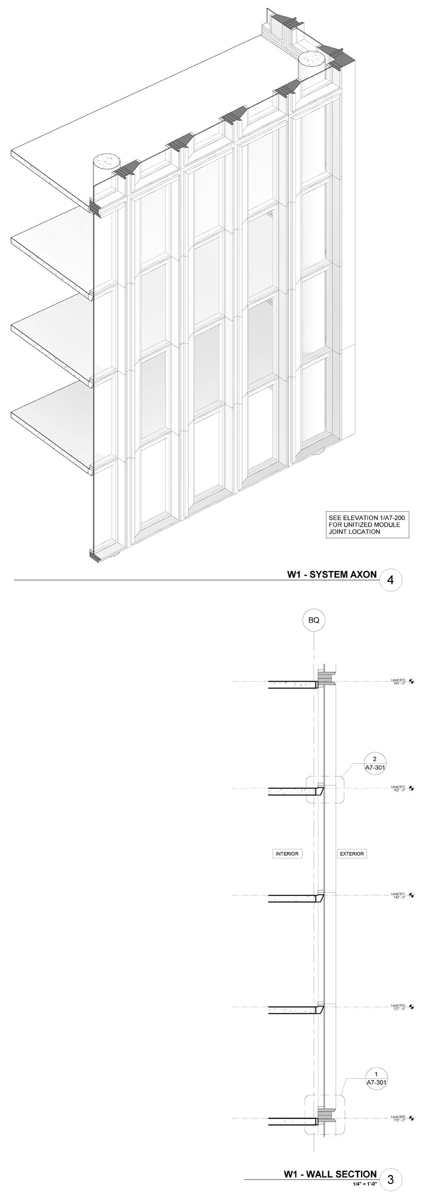
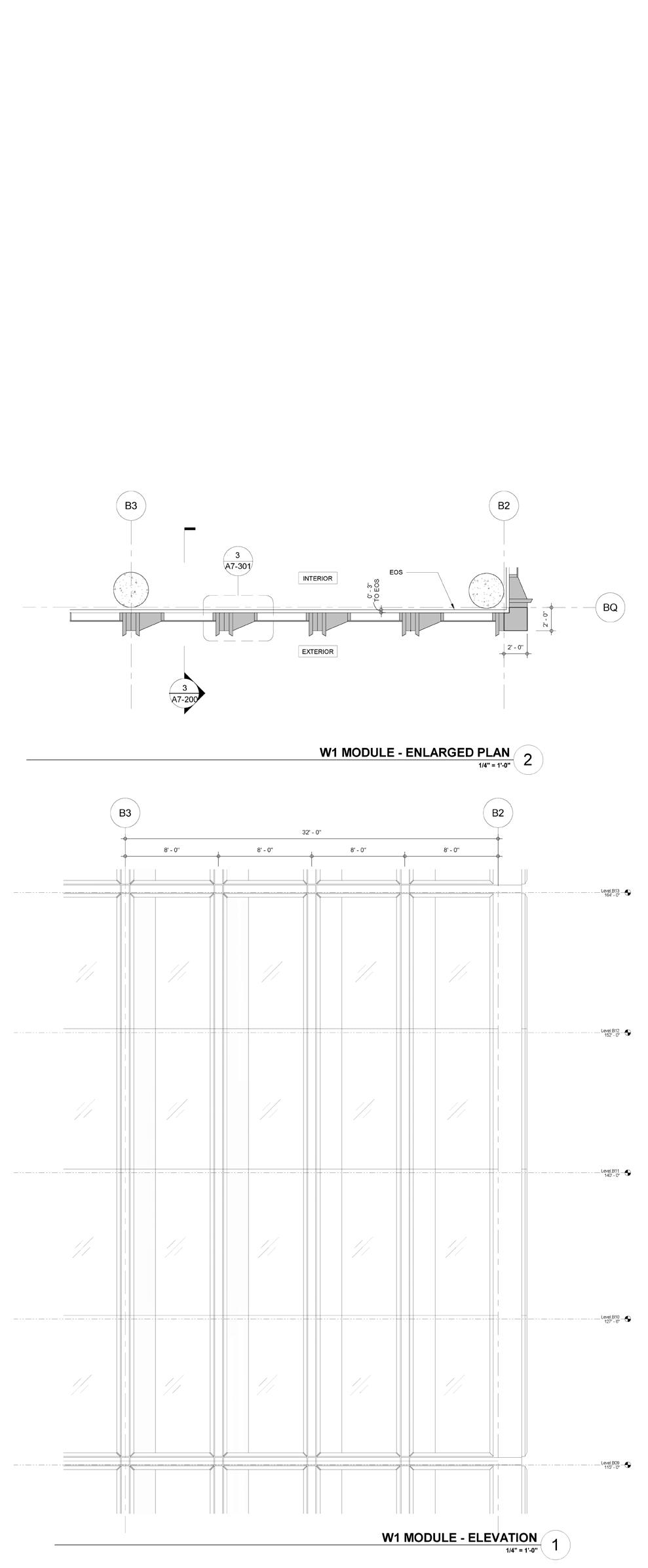
In collaboration with facade optimization and engineering consultants, Otherworks developed a glass sawtooth facade system that could accommodate the curved geometries of the tower, minimize unique conditions of panelization, and meet rigorous environmental performance requirements.
Personal Contribution
• Tower Massing Studies and Development in Rhino and Grasshopper
• Ground Floor, Roof Deck, and Plaza Studies
• Facade Development and Articulation Studies
• Coordination with Facade Engineers and Optimization Consultant
• Design Modeling, Documentation, and Rendering
• Model coordination with Project Architects
11
Concept Design, SD Otherworks 2020-2021 Seattle, Washington Office / Retail 565,000 sqft
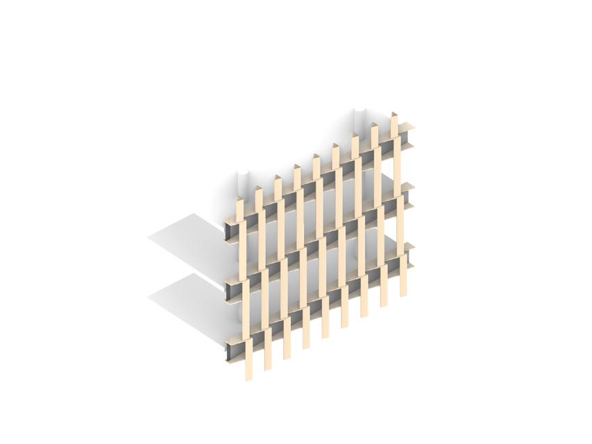


12 Seattle Tower TWIST TOWER DECK OPTIONS “Grid” “Horizontal” July 1, 2020 Page 8 Energy Code Strategy: Glazing Percentage Comparison FORM TOWER 40% Glazing Requires 50% Daylighting 50% Glazing Requires #4 Surface Low-E 60% Glazing Requires Triple Pane Glazing 18” Wide Metal Panel Clad Vertical Mullions 9” Wide Metal Panel Clad Vertical Mullions 6” Wide Metal Panel Clad Vertical Mullions Shadow box at floor slab Shadow box at floor slab Shadow box at floor slab Unitized Curtain Wall Module Unitized Curtain Wall Module Unitized Curtain Wall Module Double Pane Glazing Double Pane Glazing w/ #4 Surface Low-E Coating Triple Pane Glazing Floor Plate Floor Plate Floor Plate 5’-0” 5’-0” 5’-0” EQ EQ EQ 1’-6” 1’-6” 1’-6” 8’-6” 8’-6” 8’-6” 13’-9” 13’-9” 13’-9” 3’-9” 3’-9” 3’-9” EQ EQ EQ EQ EQ EQ EQ EQ EQ EQ EQ EQ EQ EQ EQ EQ EQ EQ 1’-0” MAX 1’-0” MAX 5’-0” TYP. 5’-0” TYP. 5’-0” TYP. 1’-0” MAX 9” Wide Metal Panel Clad Vertical Mullions 6” Wide Metal Panel Clad Vertical Mullions 18” Wide Metal Panel Clad Vertical Mullions Double Pane Glazing w/ #4 Surface Low-E Coating Triple Pane Glazing Double Pane Glazing Glazing Studies
July 2020 Page FORM TOWER: LOW RISE LEVEL Building C Tower Options 6th St. OliveWay McGraw Square LEGEND CORE SERVICES OFFICE TYPICAL LOW RISE FLOORS 14 Average Floor Area 19,010 July 1, 2020 Page 10 FORM TOWER: LEVEL 14 TERRACE Building C Tower Options 6th St. OliveWay McGraw Square FLOOR 14 Interior Floor Area 16,300 Terrace Area 2,635 LEGEND CORE SERVICES OFFICE OUTDOOR DECK AND LANDSCAPING July 1, 2020 Page 11 FORM TOWER: LEVEL 15 TERRACE Building C Tower Options 6th St. OliveWay McGraw Square LEGEND CORE SERVICES OFFICE OUTDOOR DECK AND LANDSCAPING FLOOR 15 Interior Floor Area 17,375 Terrace Area 780 Typ. Lower Level Level 14 Level 15 Floor Plans
Facade Articulation Studies
Las Palmas
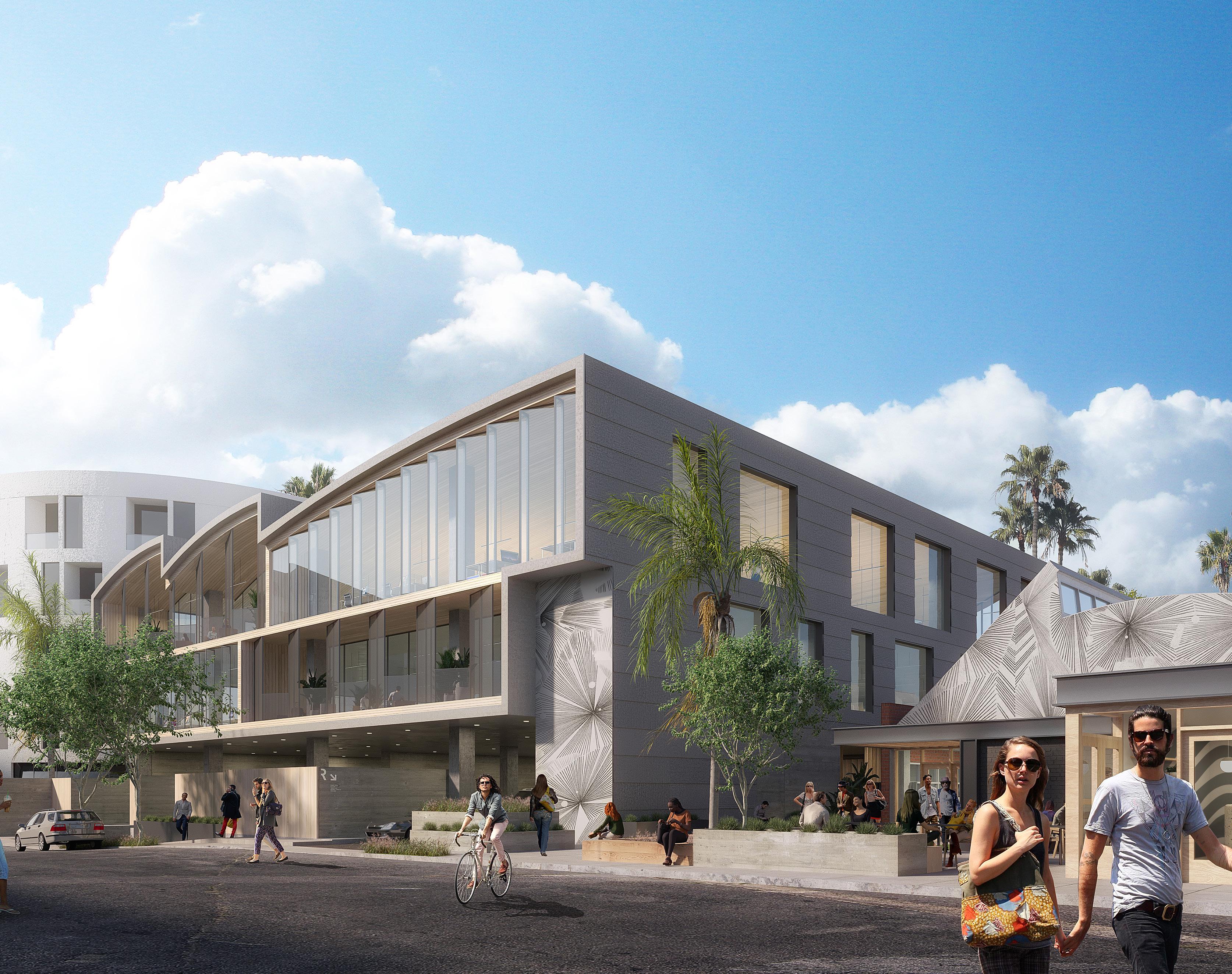
Project Description
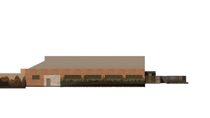
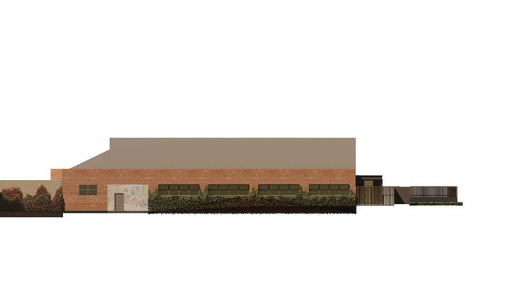
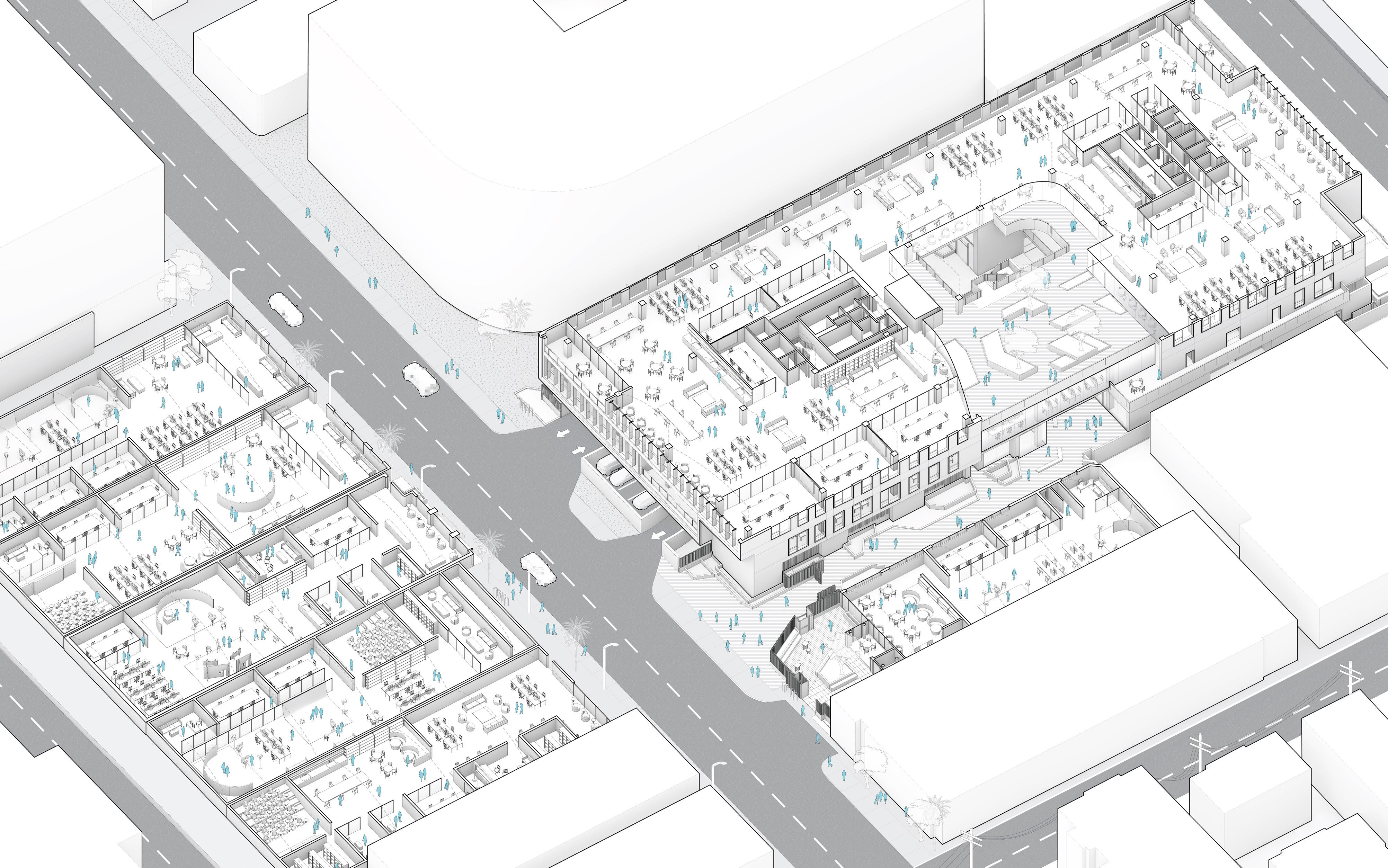
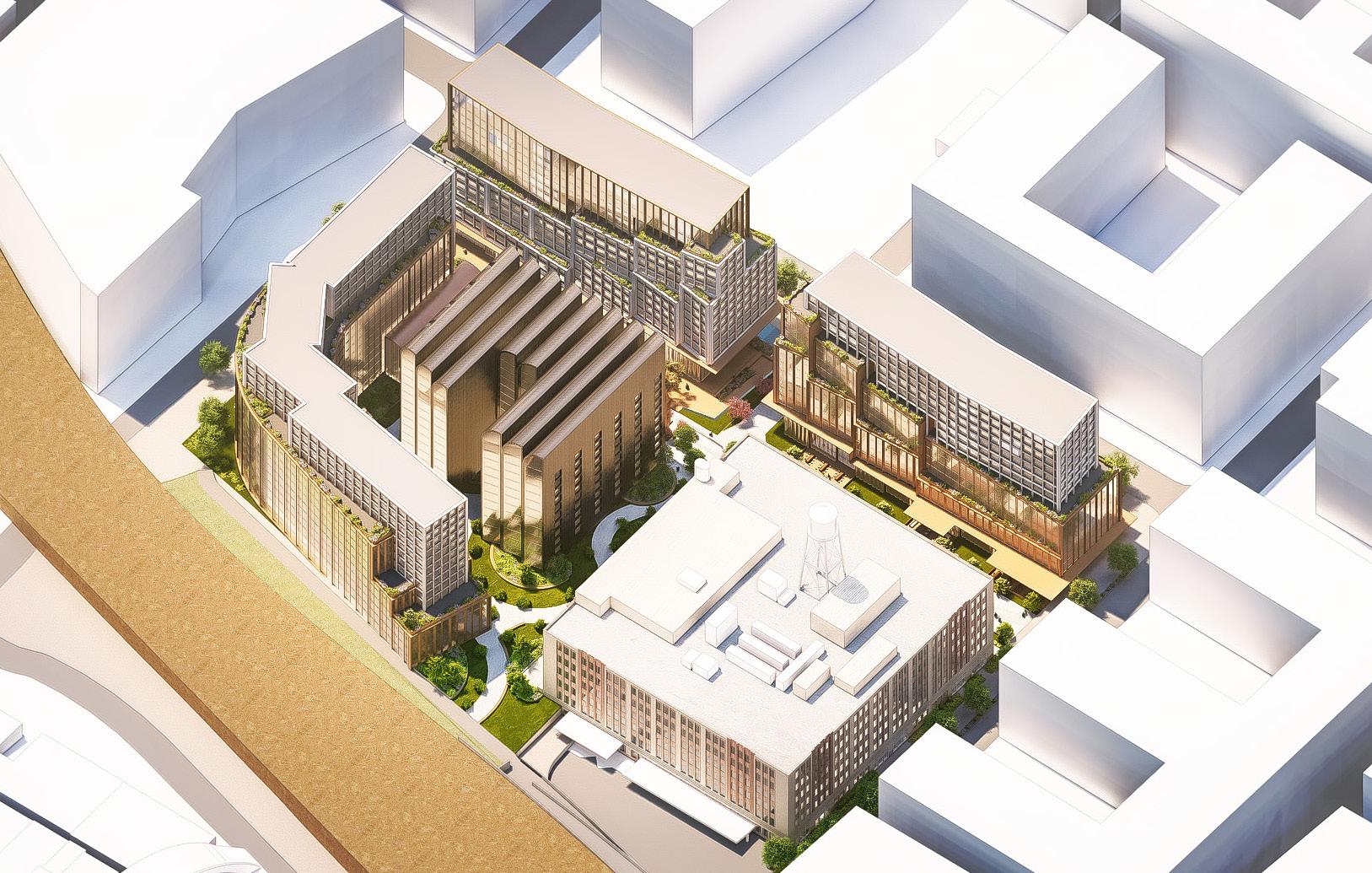
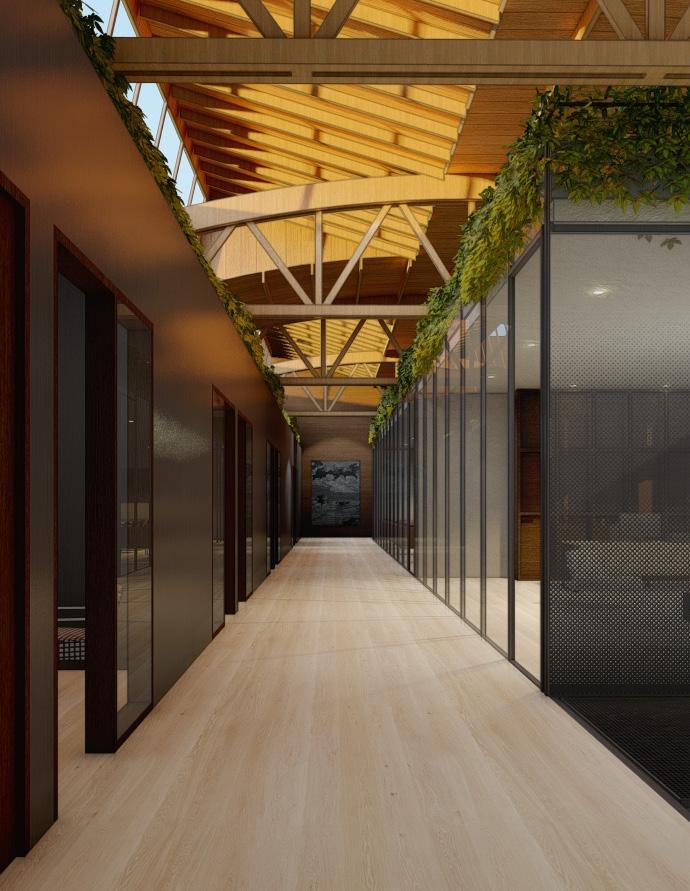
The Las Palmas project is a series of seven buildings: five existing bowstring truss buildings, on the east side of Las Palmas Avenue, facing a new 80,000 sf office building and an additional existing structure across the street.
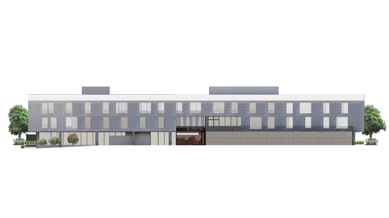
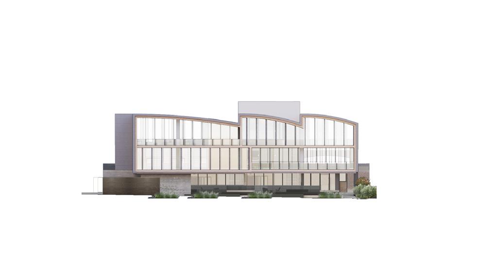
These series of buildings were conceived as a post-production and creative office campus, able to be subdivided into few or many tenants. The goal for each building was to relate to others on the campus, yet retain an individual identity. Thus the formal language of the existing bowstring truss buildings informed the shape of the new building (1151 Las Palmas), with a double arc roof and curved sawtooth profile.
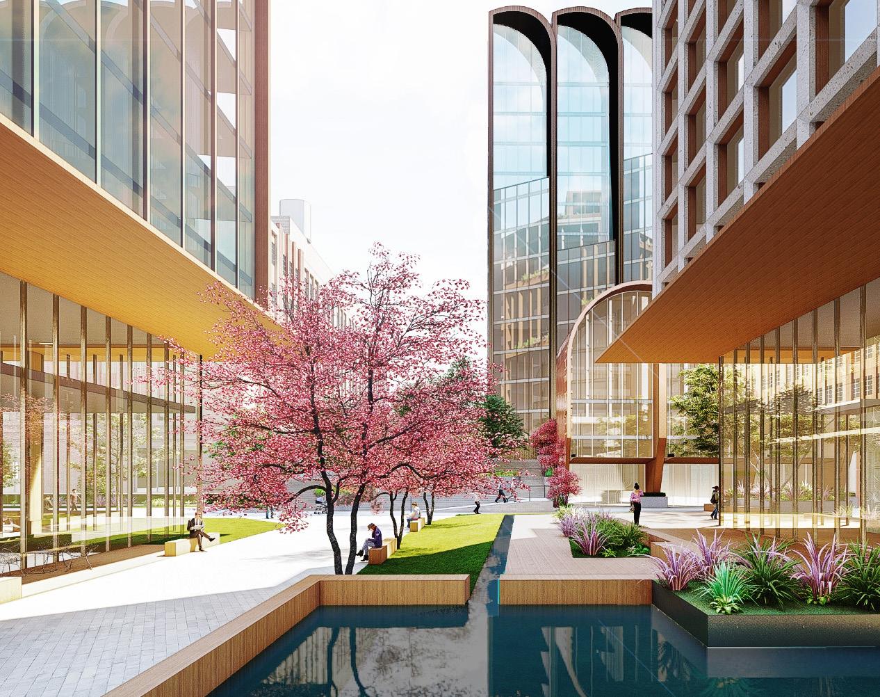
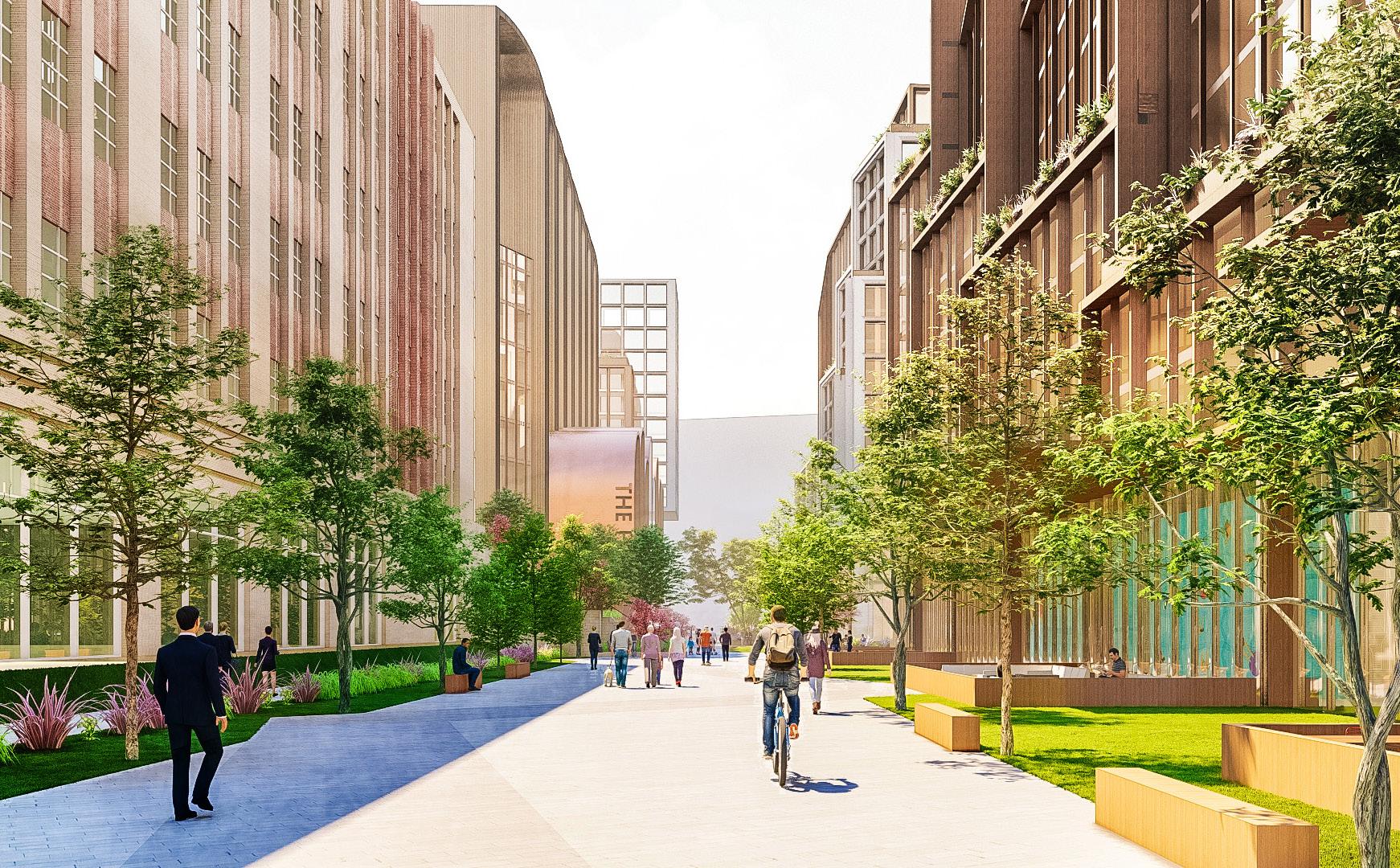
At 80,000 sf, 1151 Las Palmas anchors the project, stitching the campus together with a cross-site connection between street-facing plazas and a communal courtyard. The configuration of the buildings on campus with surrounding open space supports flexible programming arrangements for the contemporary production workplace.
Personal Contribution
• Massing and Facade Articulation Studies
• Adaptive Reuse and Renovation Studies
• Parking and Building Space Planning
• Groundscape Design
• Retail Design
• Lobby and Restroom Design
• Coordination with Project and Landscape Architects
• Design Modeling, Documentation, and Rendering
• Coordinated and Compiled Site Planning Review Submittal
15
Concept Design, SD, DD, CD Otherworks 2021-2024 Hollywood, California Creative Office / Retail 130,000 sqft
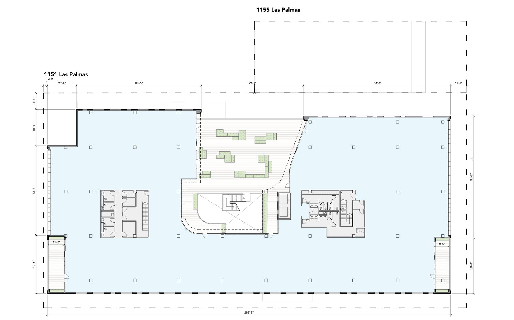

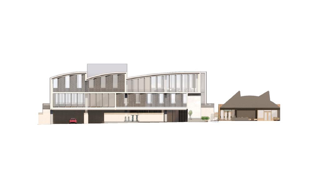
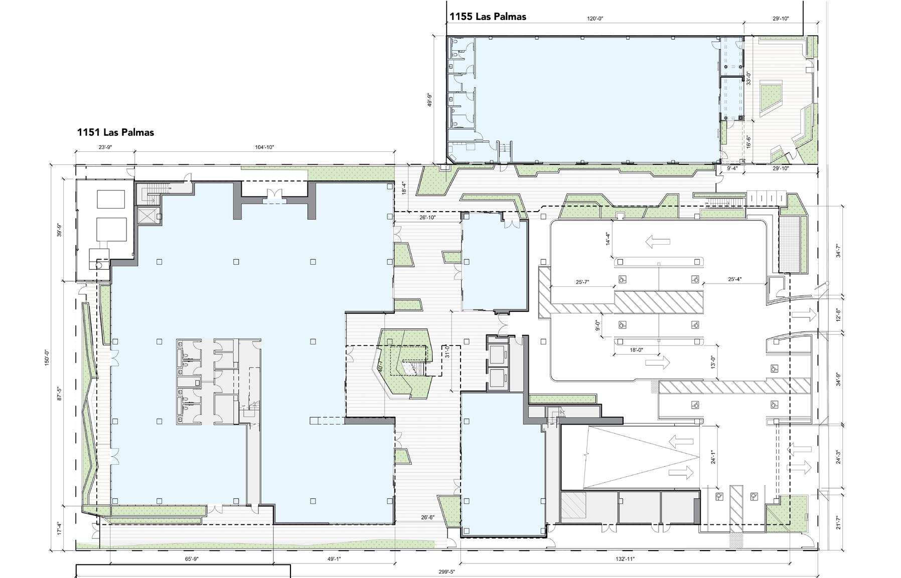

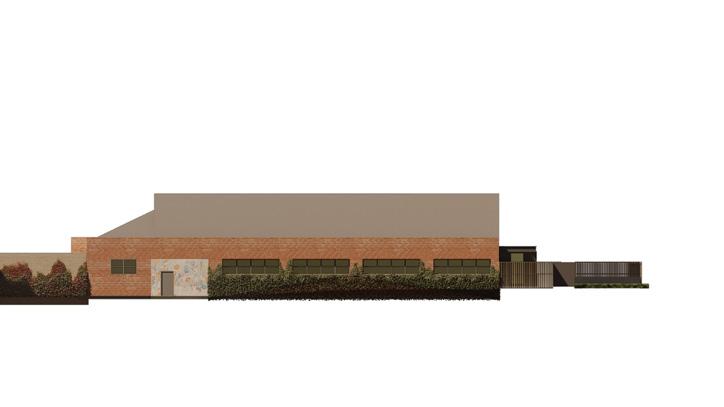
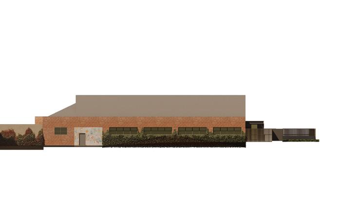
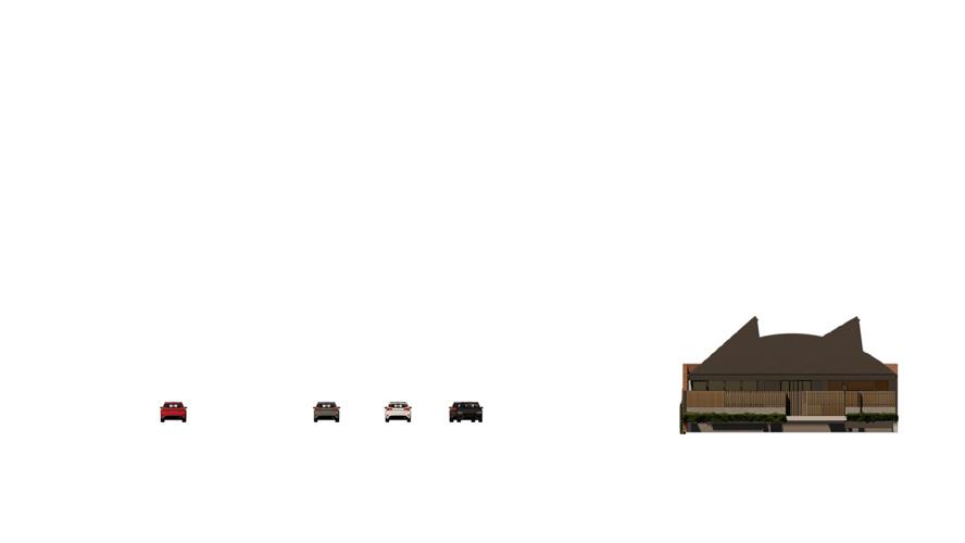
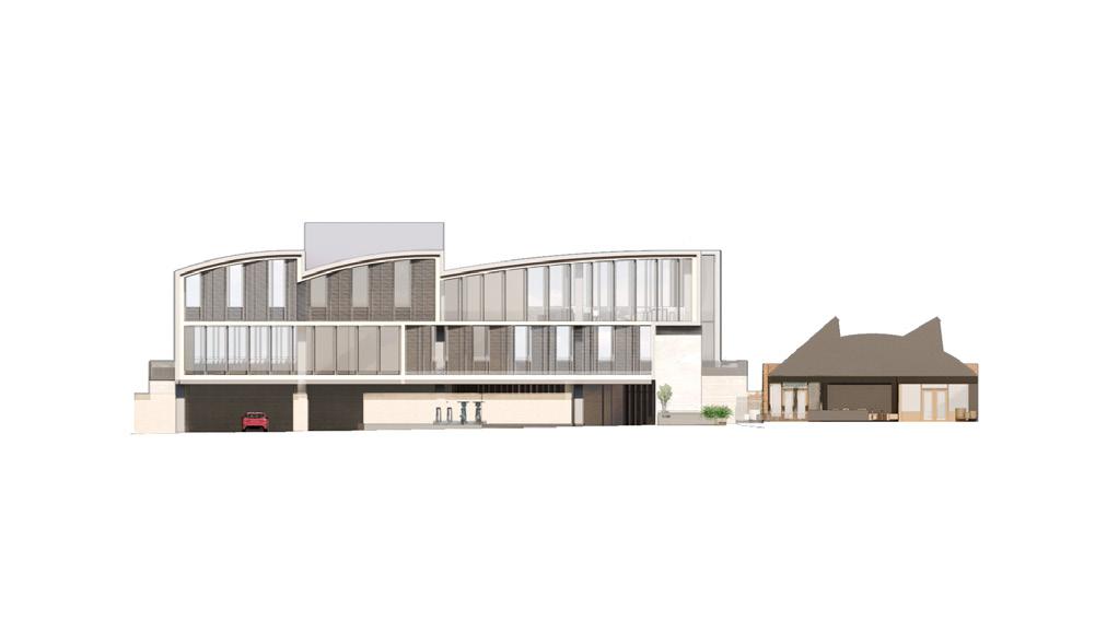
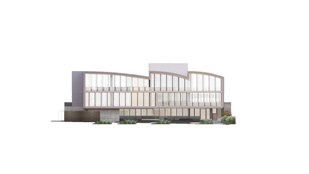
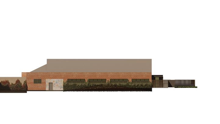
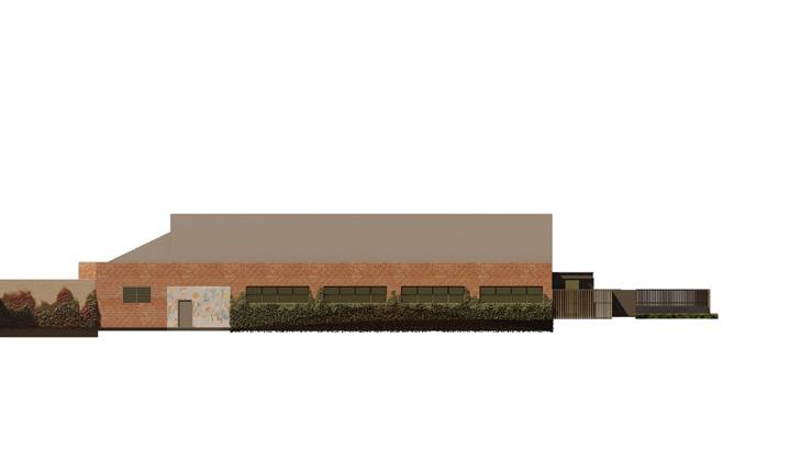
Within 1151 Las Palmas, a series of blended interior/exterior spaces are strategically integrated vertically and horizontally through the building. The placement of the central building core, connected to these terraces, maximizes building tenant flexibility without compromising daylit open floor planning, access to outdoor space, and security. The east-west passage, traversing the building site from Las Palmas Ave. to McCadden Pl, as well as the exterior stair in the central courtyard grants outdoor access to each of the building’s tenants.

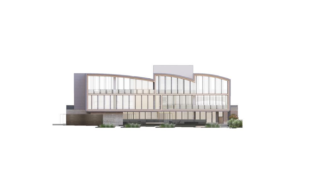
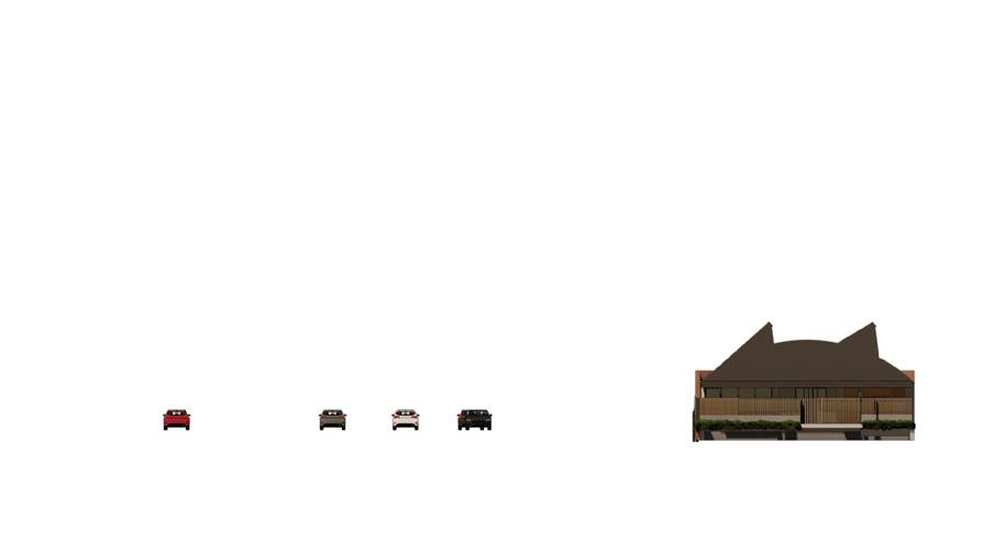
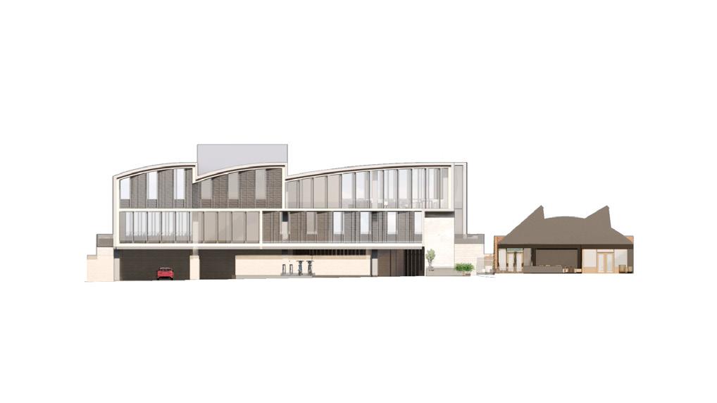

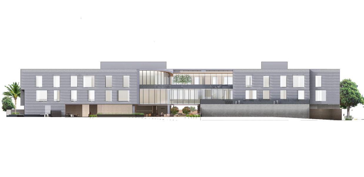
16 Ground Floor Level 3 Las Palmas
18 2A A2-201 3 1 2 T.O.S. 2F T.O.S. 3F T.O.S. ROOF T.O. MECH T.O.S. 1F 3'-0" LOWEST NATURAL GRADE 0'-0" 12'-6" 12'-6" 17'-0" 3'-0" 45'-0" MAX. 15'-6" 28'-0" 45'-0" 50'-0" FROM LOWEST NATURAL GRADE T.O.S. 2F T.O.S. 3F T.O.S. ROOF T.O. MECH 15'-6" 28'-0" 45'-0" 50'-0" 12'-6" 12'-6" 17'-0" LOWEST NATURAL GRADE 0'-0" T.O.S. 1F 3'-0" 3'-0" 45'-0" MAX. T.O.S. ROOF 30'-0" 30'-0" T.O.S. ROOF 12'-0" EAST ELEVATION A3-302 A2-201 FROM LOWEST NATURAL GRADE T.O.S. 2F T.O.S. 3F T.O.S. ROOF T.O. MECH T.O.S. 1F 3'-0" A3-302 A2-201 A2-201 A2-202 30'-0" T.O. WALL 10'-0" LOWEST ELEVATION 302.42' CORRELATES TO SHEET V0-001 LOWEST NATURAL GRADE 0'-0" 12'-6" 12'-6" 17'-0" 3'-0" 45'-0" MAX. 15'-6" 28'-0" 45'-0" 50'-0" 5 3 2 FROM LOWEST NATURAL GRADE T.O.S. 2F T.O.S. 3F T.O.S. ROOF T.O. MECH 15'-6" 28'-0" 45'-0" 50'-0" A3-301 A2-201 A2-201 CORRELATES TO SHEET V0-001 12'-6" 12'-6" 17'-0" LOWEST NATURAL GRADE 0'-0" T.O.S. 1F 3'-0" 3'-0" 45'-0" MAX. 5 3 2 T.O.S. ROOF 30'-0" 30'-0" T.O.S. ROOF 12'-0" EAST ELEVATION A3-302 A2-201 FROM LOWEST NATURAL GRADE T.O.S. 2F T.O.S. 3F T.O.S. ROOF T.O. MECH T.O.S. 1F 3'-0" A3-302 A2-201 A2-202 30'-0" T.O. WALL 10'-0" LOWEST ELEVATION 302.42' LOWEST NATURAL GRADE 0'-0" 12'-6" 12'-6" 17'-0" 3'-0" 45'-0" MAX. 15'-6" 28'-0" 45'-0" 50'-0" 4 1 PROJECT NAME: CLIENT: 923 E. 3RD STREET, SUITE LOS ANGELES, CA 90013 2103 NO. DESCRIPTION KEY PLAN: DRAWING NO: PROJECT NO: PROJECT SCALE: DRAWING TITLE: DECEMBER 2022 DESIGN ARCHITECT: EXECUTIVE ARCHITECT: LANDSCAPE ARCHITECT: 1128-1146 N LAS PALMAS AVENUE 1139-1155 N LAS PALMAS AVENUE 1138-1150 N MCCADDEN PLACE LOS ANGELES, CA 90038 APN: 5532-021-003, 004, 005, 014, 5532-022-003, 004, 005, 006 1149 LAS PALMAS A2-202 1/16” = 1’- 0” ELEVATIONS NEW BUILDING 1155 LAS PALMAS 10 25 1/16” 1’-0” KEYNOTES: GFRC ALUMINUM WINDOW FRAMES HIGH PERFORMANCE GLAZING PERFORATED METAL METAL PANEL SIMULATED WOOD BOARD FORM CONCRETE PAINTED STEEL 2A PAINTED STUCCO WOOD CLAD STOREFRONT **NOTE: T.O.S, T.O.P., AND TOP OF MECHANICAL MEASUREMENTS TAKEN FROM LOWEST NATURAL GRADE EXISTING BRICK 10 RESURFACED BRICK 11 EXISTING STEEL WINDOW 12 NEW OPERABLE WINDOWS 13 ACCOYA WOOD FENCE 17 WINDOW WALL 18 GLASS HANDRAIL 19 PAINTED CONCRETE COLUMNS GREEN WALL SHOTBLAST STACK BOND CMU WALL 16 15 14 WALL AT PROPERTY LINE PAINTED PLASTER WALL 20 21 (N) RECONFIGURED FACADE (E) BUILDING (N) MECHANICAL ON EXISTING 1155 22 23 24 1/16” = 1’ 0” 1 1155 EAST ELEVATION LAS PALMAS AVE 1/16” 0” 3 1155 SOUTH ELEVATION 1/16” 1’ 0” 4 1149 WEST ELEVATION MCCADDEN PL 1/16” 0” 2 1149 EAST ELEVATION LAS PALMAS AVE 2 5 3 6 18 18 7 10 21 16 17 17 19 18 5 20 23 22 22 24 13 3 17 2A 2A
18 19 Las Palmas
NoMA Station
Project Description
NoMA Station, named for the historic building on site currently serving a federal government office, is slated to be a multi-family residential, mixeduse development providing over 1,200 residential units, 40,000sf of retail, and 760 parking spaces.
With the expected market and demographic growth of the immediate neighborhood, the project’s parking basement, podium, and residential buildings are planned to be developed over two distinct building phases. Each of the project’s four buildings had a different unit type ratio and unit square footage target depending on their sequence in the phasing and projected target market.
Personal Contribution
• Massing and Facade Articulation Studies
• Building Code and Zoning Research
• Parking and Building Space Planning
• Unit Planning and Calculations
• Groundscape Design
• Coordination with Civil Engineers
• Design Modeling, Documentation, and Rendering for Client and Coordination Meetings
21
Concept Design Otherworks 2023-2024 Washington, D.C. Multi-family Residential, Mixed-Use 1,200,000 sqft
BUILDING 1A TYPICAL FLOOR LAYOUT

22 23 NOMA Station () Page 9 B1 ENTRY RAMP FROM M ST GARAGE B1 166,615 GSF 1:200 833 OCC. -1 YAR E 133'-6"S 225'-3" NO BUILD-TO LINE REQUIREMENT 75'-0" 67'-9" 24'-0" NO BUILD-TO LINE REQUIRED 75'-11" 38'-10" December 11, 2023 Page 10 PHASE 2 GROUND PLANE STUDIES GROUND PLANE SITE PLANNING L1 FIRST ST NE M ST NE L ST NE (E) SERVICE ENTRY ONE NOMA LOBBY 1A 4,430 SF LOBBY 1B 4,195 SF RETAIL 1,821 SF RETAIL 1,821 SF RETAIL 1,821 SF RETAIL 1,821 SF LOBBY 2A 3,680 SF RETAIL 3,958 SF RETAIL 2,275 SF RETAIL 1,875 SF RETAIL 1,645 SF RETAIL 2,566 SF RETAIL 2,566 SF RETAIL 2,851 SF RETAIL 2,848 SF RETAIL 1,837 SF RETAIL 1,928 SF RETAIL 3,742 SF RETAIL 2,189 SF LOBBY 2B 3,845 SF RETAIL 1,368 SF RETAIL 1,822 SF SERVICE 5,575 SF RETAIL 2,867 SF PARKING 47,985 SF EL. +38’-4” EL. +37’ EL. +38’ EL. +37’ EL. +38’ EL. +39’ EL. +40’ EL. +41’ EL. +42’ EL. +43’ PRIMARY STREET REQUIREMENTS (1st St NE) RequiredProvided Ground Floor Uses (GSF) 50% 90.9% Total Frontage 100% 100% Min. Net Leasable Area of Ground Floor Uses 80% 90.9% Front Build‐to Property Line (First St NE ‐ within 4' of porperty line) 75% (454.56') 92.9% (563'‐1") SETBACKS RequiredProvided Front Yard None None Side Yard (2" per 1' Height) 21'‐8"42‐11" min. Rear Yard (2.5" per 1' Height) 27'‐1" n/a FAR MaximumProvided Residential None None Non‐Residential 6.5 1.55M SF Mixed Use, Non‐residential Portion = 6.5 None + 1.55M SF BUILDING HEIGHT MaximumProvided 1st St NE ROW 110' ROW > 110' 130'H max. 130' 130' COURTS³ RequiredProvided Residential Min. Width Open: 4" per 1' of height of court, 10' min. 43'‐4" min. 43'‐0" Min. Width Closed: same, 15' min. 43'‐4" min. n/a Min. Area Closed: 2x square of required width of court, 350 SF min. 3,756 SF 3,227 SF Non‐Residential and Lodging TBD TBD Min. Width Open: 2.5" per 1' of height of court, 6' min. 27'‐1" min. 43'‐0" Min. Width Closed: same, 12 ft min. 27'‐1" min. n/a Min. Area Closed: 2x square of required width of court, 250 SF min. 1,467 SF 3,227 SF GREEN AREA RATIO RequiredProvided D‐ (0.2 calculated based on landscape type multipliers) 47,596.8Per Landscape Plan DRIVEWAY LOCATION Min. distance from lot line abutting public street 20' > 61' 1.24M SF (5.12 FAR) EL. +38’-4” (N) PARKING RAMP (N) PARKING ENTRY Parking and Ground Floor Planning 29'-7 82'-6" 15'-0 41'-1" 15'-0 7'-6" 288'-0 37'-2" 44'-0" 34'-7" 31'-6 38'-10 23'-1 21'-0 15'-0 21'-0 31'-4 21'-0 16'-0 16'-0 16'-0 21'-6 21'-0 16'-0 16'-0 16'-0 16'-0 21'-6 21'-6 15'-0 24'-5 23'-0 21'-6 29'-7 1/32” = 1’-0” December 11, 2023 Page 12
TARGET TOTAL COUNT UNIT RANGE UNIT MIX AVG. AREA STUDIO 49 400-450 15% 425 JR. 1BED/1BATH 81 525-575 25% 550 1BED/1BATH 98 600-700 30% 650 1BED/1BATH +DEN 33 750-850 10% 800 2BED/2BATH 65 925-1,075 20% 1,000 TOTAL 326 676 PROVIDED TOTAL COUNT PER FLOOR UNIT RANGE UNIT MIX AVG. AREA STUDIO 49 4 489 15.0% 489.0 JR. 1BED/1BATH 81 7 553 24.8% 553.0 1BED/1BATH 98 8 653-684 30.1% 668.5 1BED/1BATH +DEN 33 3 795-809 10.1% 802.7 2BED/2BATH 65 5 967-1,051 19.9% 1,010.4 TOTAL 326 27 690.2 LEGEND Studio Jr. 1Bed / 1Bath 1Bed / 1Bath 1Bed / 1Bath + Den 2 Bed 2 Bath UNIT SUMMARY TOTAL FLOOR AREA: 22,520 GSF FLOOR EFFICIENCY: 85.7% 2B/2B TYPE 984 SF 2B/2B TYPE IV 1,003 SF 2B/2B TYPE II 967 SF 2B/2B TYPE III 1,047 SF JR. 1B/1B 553 SF JR. 1B/1B 553 SF JR. 1B/1B 553 SF JR. 1B/1B 553 SF JR. 1B/1B 553 SF JR. 1B/1B 553 SF JR. 1B/1B 553 SF STUDIO 489 SF STUDIO 489 SF 1B/1B TYPE 684 SF 1B/1B TYPE II 653 SF 1B/1B TYPE II 653 SF 1B/1B TYPE II 653 SF 1B/1B TYPE II 653 SF 1B/1B TYPE 684 SF 1B/1B + DEN TYPE 809 SF 1B/1B + DEN TYPE 804 SF 2B/2B TYPE V 1,051 SF STUDIO 489 SF STUDIO 489 SF EL. TR. 1B/1B TYPE 684 SF 1B/1B TYPE 684 SF 1B/1B DEN TYPE 795 SF P P F 30'-0" 7'-6" 77'-6 77'-6 70'-0" 7'-6" 30'-0" 36'-10" 00 26 226 20'-4" 44'-1 22'-8" 2414 200 35'-10" 26 20 23'-0" 2223'-0" 22225'-0" 23'-0" 28'-11" 24-9 2024-9 31'-9" 17'-4" 174 3237'-6" 25'-1" 1623'-0" 26 3223'-0" 411 24 -9 31 16100 TR. TR. ELEC. ELEC. SERV. 1/32” = 1’-0” December 11, 2023 LEGEND Studio Jr. 1Bed 1Bath 1Bed 1Bath 1Bed 1Bath + 2 Bed / 2 Bath 2 Bed / 2 Bath + BUILDING 2A | L3-11 TYPICAL FLOOR LAYOUT UNIT SUMMARY TARGET TOTAL COUNT UNIT RANGE UNIT MIX AVG. AREA STUDIO 45 475-525 10% 500 JR. 1BED/1BATH 135 600-650 31% 625 1BED/1BATH 135 675-775 31% 725 1BED/1BATH +DEN 45 825-875 10% 850 2BED/2BATH 68 950-1,150 16% 1,050 2BED/2BATH + DEN 10 1,175-1,225 2% 1,200 TOTAL 438 758 PROVIDED (9 FLOORS) TOTAL COUNT PER FLOOR UNIT RANGE UNIT MIX AVG. AREA STUDIO 36 4 481-557 11% 538 JR. 1BED/1BATH 108 12 601-707 32% 626 1BED/1BATH 108 12 660-749 32% 697 1BED/1BATH +DEN 27 3 828-1,008 8% 937 2BED/2BATH 45 5 960-1,099 14% 1,023 2BED/2BATH +DEN 9 1 1,163 3% 1,163 TOTAL 333 37 733 TOTAL FLOOR AREA: 33,010 SF FLOOR EFFICIENCY: 85.1% 2B/2B/D TYPE 1,163 SF 2B/2B TYPE V 1,002 SF 2B/2B TYPE IV 1,017 SF 2B/2B TYPE 1,099 SF 1B/1B TYPE 738 SF 1B/1B TYPE II 709 SF 1B/1B TYPE III 692 SF 1B/1B TYPE III 692 SF 1B/1B TYPE III 692 SF 1B/1B TYPE IV 676 SF 1B/1B TYPE IV 676 SF 1B/1B TYPE 660 SF 1B/1B TYPE VI 722 SF 1B/1B TYPE VII 749 SF 1B/1B TYPE IV 676 SF 1B/1B TYPE IV 676 SF JR. 1B/1B TYPE 601 SF JR. 1B/1B TYPE II 601 SF JR. 1B/1B TYPE 642 SF JR. 1B/1B TYPE II 601 SF JR. 1B/1B TYPE II 601 SF STUDIO TYPE 557 SF STUDIO TYPE 557 SF STUDIO TYPE II 557 SF JR. 1B/1B TYPE III 707 SF JR. 1B/1B TYPE VII 623 SF JR. 1B/1B TYPE VII 623 SF JR. 1B/1B TYPE VII 623 SF JR. 1B/1B TYPE VI 641 SF JR. 1B/1B TYPE V 634 SF JR. 1B/1B TYPE IV 613 SF 2B/2B TYPE II 1,036 SF 2B/2B TYPE III 960 SF 1B/1B/D TYPE 974 SF 1B/1B/D TYPE III 828 SF STUDIO TYPE 481 SF 1B/1B/D TYPE II 1,008 SF Building Planning
Post-Production Tenant Feasibility Study
Project Description
Otherworks conducted a series of space planning and feasibility studies for a potential Hollywood writer/ director leasing an adaptive reuse creative office space. Spanning 2-4 existing buildings, the post-production studio would include editing suites, production offices, screening rooms, as well as communal creative office space and amenities. Program adjacencies were carefully considered given the acoustical isolation requirements, privacy concerns, and production workflow preferences of the client.
Personal Contribution
• Existing Building Evaluation
• Programming and Adjacency Studies
• Space Planning
• Diagrams, Drawings, Modeling, Rendering
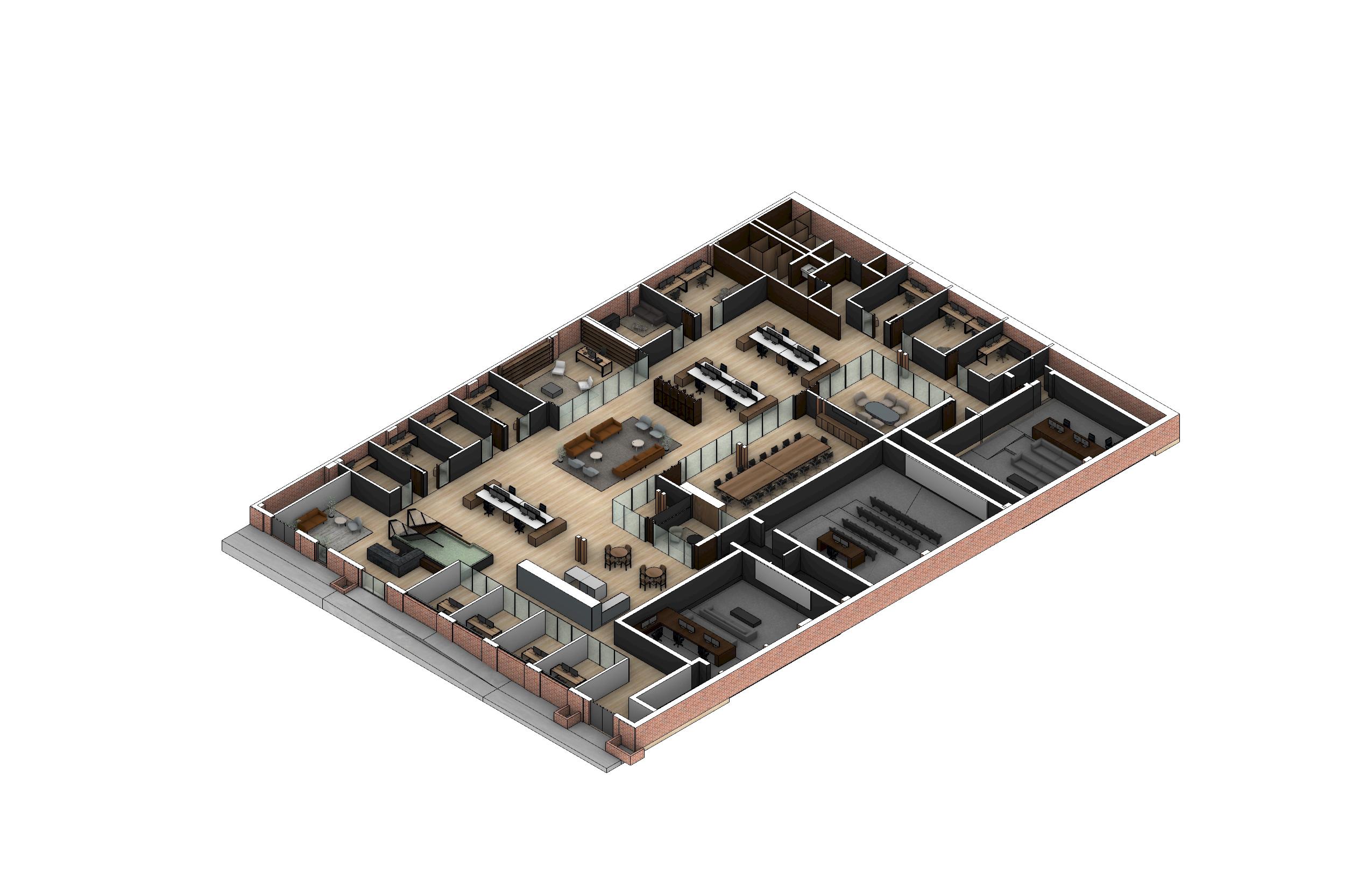

25 November 04, 2022 Page 7 DIRECTOR’S OFFICE DEVELOPMENT BULLPEN RECEPTION AREA DEVELOPMENT OFFICES SMALL PRODUCTION OFFICES LARGE PRIMARY EDITING SUITES SCREENING ROOM KITCHENETTE WRITERS’ ROOM RESTROOMS PRODUCTION BULLPEN EDITING SUITE MEDIUM PRODUCTION OFFICES BREAKOUT PHONE ROOM COMMON AREA CONFERENCE ROOM EDITING SUITE MEDIUM PRODUCTION OFFICE SMALL PRODUCTION OFFICE LEVEL 01 AXON 1st FLOOR 65'-0" 6'-0" 30'-9" 32'-5" 40'-1" 19'-11" 4'-4" 34'-1" 43'-6" 24'-7" 11'-5" 4'-3" 31'-6" 47'-3" 36'-10" 5'-1" 24'-10" 20'-1" 13'-11" 10'-0" 20'-8" 80 sf 112 sf 140 140 sf 140 sf 415 sf 200 sf 253 sf 202 sf 154 sf 211 sf 176sf 104 760 sf 767 sf 51 sf 140 sf 140 sf 140 sf 140 sf 567 sf 584 sf 395 sf 620 sf 632 76 sf 794 sf 359 98 sf 1218 sf 138 sf 202 sf 85 sf Reception UP Services Storage Dev. Office 1/4 Vestibule Projector Room Primary Editing Suite 1/2 (Acoustically Isolated) Women's RR Men's RR (E) Electrical Room Primary Editing Suite 2/2 (Acoustically Isolated) Kitchenette Common Area Writers' Room Med. Prod. 1/2 (Baffled) Editing Suite 1/2 (Baffled) Editing Suite 2/2 (Baffled) Med. Prod. 2/2 (Baffled) Conference Room Phone Room Breakout Room Sm. Prod. 1/5 (Baffled) Sm. Prod. 2/5 (Baffled) Sm. Prod. 3/5 (Baffled) Sm. Prod. 4/5 (Baffled) Sm. Prod. 5/5 (Baffled) Director's Office Screening Room (Acoustically Isolated) Dev Office 2/4 Dev. Office 3/4 Dev. Office 4/4 (E) Electrical Room Prod. Bullpen Dev. Bullpen Vestibule Services Storage Vestibule November LEVEL 01 FLOOR PLAN DEVELOPMENT PRODUCTION COMMUNAL SPACES SCALE = 1/16” = 1’-0” LEVEL 01 FLOOR PLAN DEVELOPMENT PRODUCTION COMMUNAL SPACES SCALE = 1/16” = 1’-0”
Concept Design Otherworks 2022 Hollywood, California Post-Production Office 14,000 sqft
San Francisco Flower Mart
Project Description
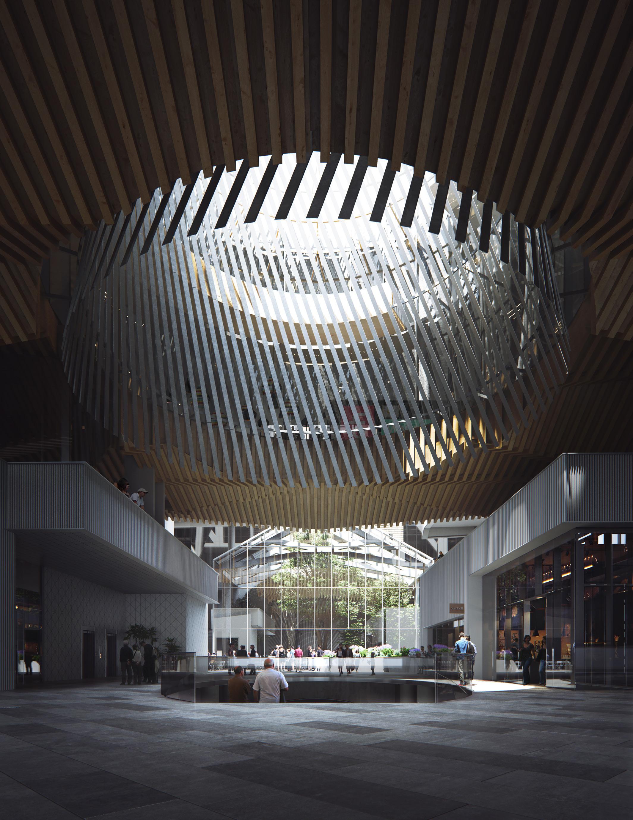
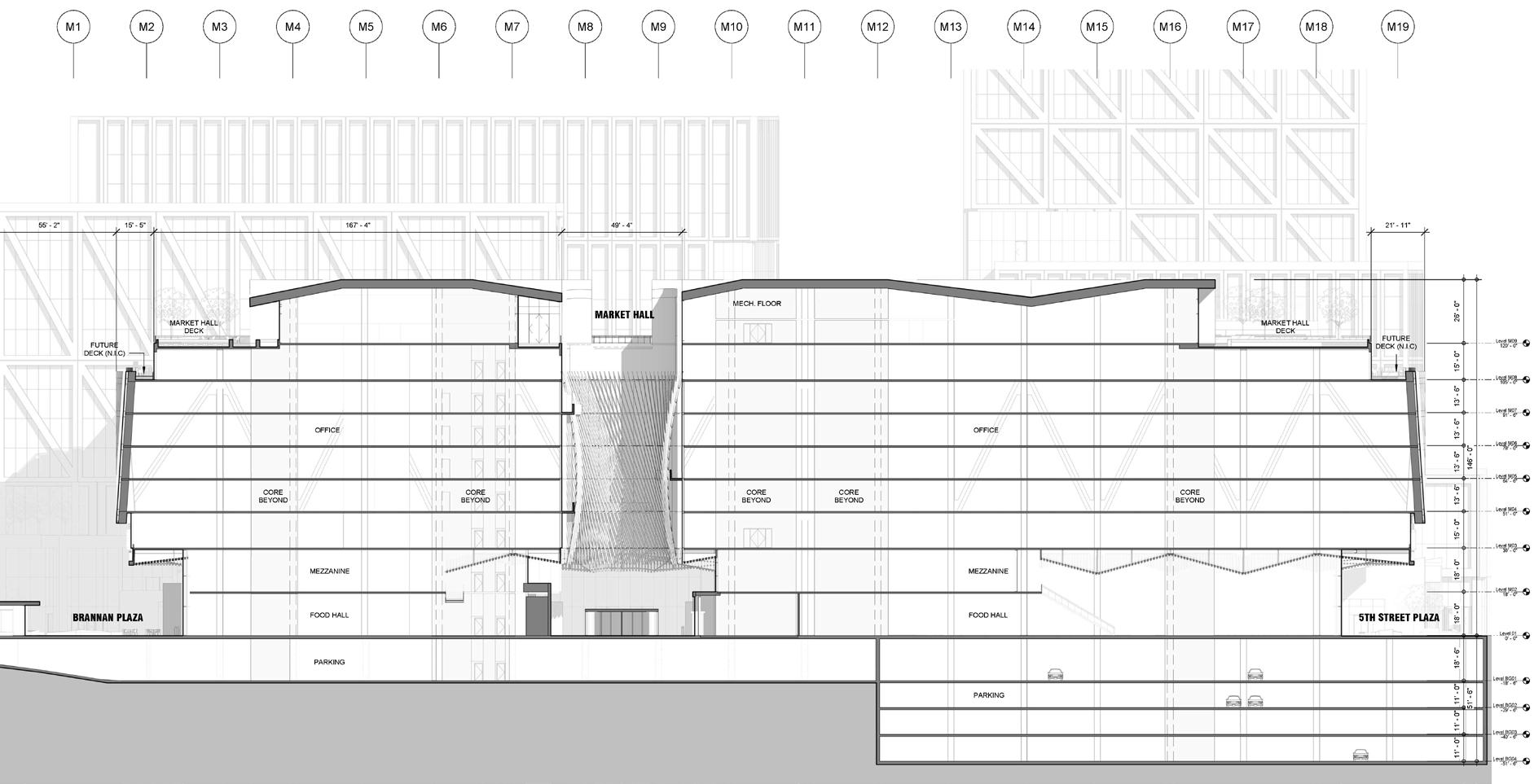
As the historic San Francisco Flower Market makes its new home in Potrero Hill, the new Flower Mart Project at 6th and Brannan builds upon its industrious legacy and fulfills the site’s new role as an urban mixed-use center.
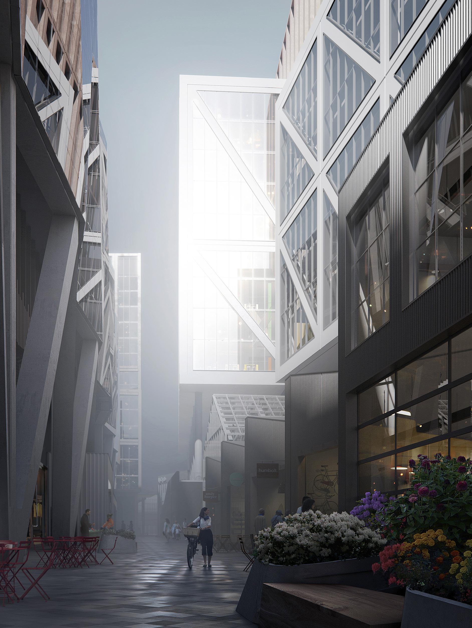
The new Flower Mart Project will encompass 2 million sqft of creative office space, 100,000 sqft of retail/ market hall, and 40,000 sqft of public open space, linked to the surrounding community and embedded in the Central SoMa Plan.
The project is composed of three main elements: the Blocks Building, the Market Hall, and the Gateway Building. The overall form and articulation of each building has been tuned to actualize distinct program typologies.
Personal Contribution
• Assisted with DD Documentation in Revit including building elevations, sections, and wall module types
• Retail and groundscape design studies
• Facade modeling and articulation studies
27
SD, DD Rios 2017-2019 San Francisco, California Office / Retail 2,100,000 sqft
28 29 San Francisco Flower Mart

Project Description
Sited on a narrow, saddle-shaped property along the north edge of the Los Angeles State Historic Park, the Buena Vista project undertook several challenges at once: to provide neighborhood-serving retail and public open space connected to adjacent Chinatown, minimize obstruction of sensitive neighbors’ views, and provide more than 900 apartment units.
The result is a development split between two sides of the site. The bulk of the project’s area sits on a podium providing access to parking, retail, commercial office space, and apartments. To minimize obstructing the views of the surrounding neighborhoods toward downtown, the project’s remaining number of living units are concentrated in two high-rise towers at opposite ends of the site.
Semi-enclosed courtyards along the southern edge of the project provide public open space, additional retail and live/work opportunities, as well as a visual connection to the Historic Park and Downtown Los Angeles beyond.
Personal Contribution
• Project modelling, diagramming, and rendering
• Space planning
• Facade studies and modeling
• Unit planning
31
Concept Design Rios 2018-2019 Los Angeles, California Multi-Family Residential 1,200,000 sqft
Buena Vista

32 33 Buena Vista KEY E D NT A E A AMENITY LOBBY SERVICE MECH RM O E RC A ON A K PLANS Ground Floor Plan South Portion Micro Unit Podium 395 sf 1 Bedroom Podium 770 sf 1 Bedroom Buildings 1&2 833 sf BEDROOM PODIUM 834 SF 1 BEDROOM BUILDINGS 1&2 833 SF SOUTH PORTION SCALE: 3/16”=1’-0” ENTITLEMENT PACKAGE BUENA VISTA OCTOBER 04, 2019 STUDIO PODIUM 554 SF 1 BEDROOM PODIUM 770 SF PORTION 3/16”=1’-0” PACKAGE OCTOBER 04, 2019 PLANS MICRO UNIT PODIUM 395 SF STUDIO PODIUM 554 SF PORTION 3/16”=1’-0” ENTITLEMENT PACKAGE VISTA OCTOBER 04, 2019 PLANS 2 Bedroom Podium 1042 sf 1 Bedroom Bar Building 780 sf 2 Bedroom Bar Building 1066 sf KEY R D N R A L AMENITY LOBBY SERVICE MECH RM CO E C C L O P G PLANS Ground Floor Plan North Portion 2 BEDROOM PODIUM 1042 SF SOUTH PORTION SCALE: 3/16”=1’-0” ENTITLEMENT PACKAGE BUENA VISTA OCTOBER 04, 2019 UNIT PLANS STUDIO COURTYARD BUILDING 450 SF 1 BEDROOM BAR BUILDING 780 SF NORTH PORTION SCALE: 3/16”=1’-0” ENTITLEMENT PACKAGE BUENA VISTA - OCTOBER 04, 2019 UNIT PLANS 2 BEDROOM BAR BUILDING 1066 SF NORTH PORTION SCALE: 3/16”=1’-0” ENTITLEMENT PACKAGE BUENA VISTA OCTOBER 04, 2019 UNIT PLANS
Canyon House
Project Description
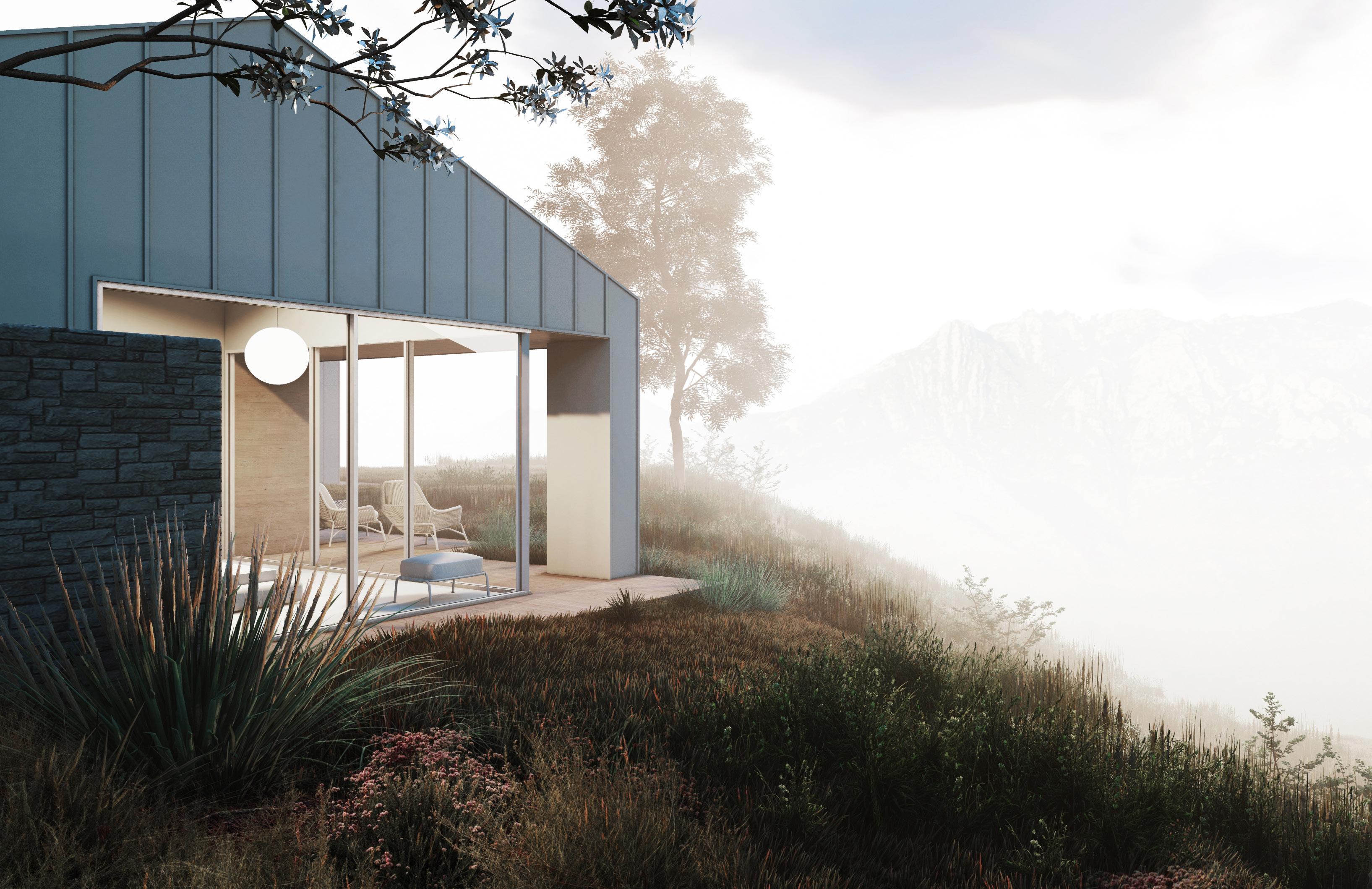
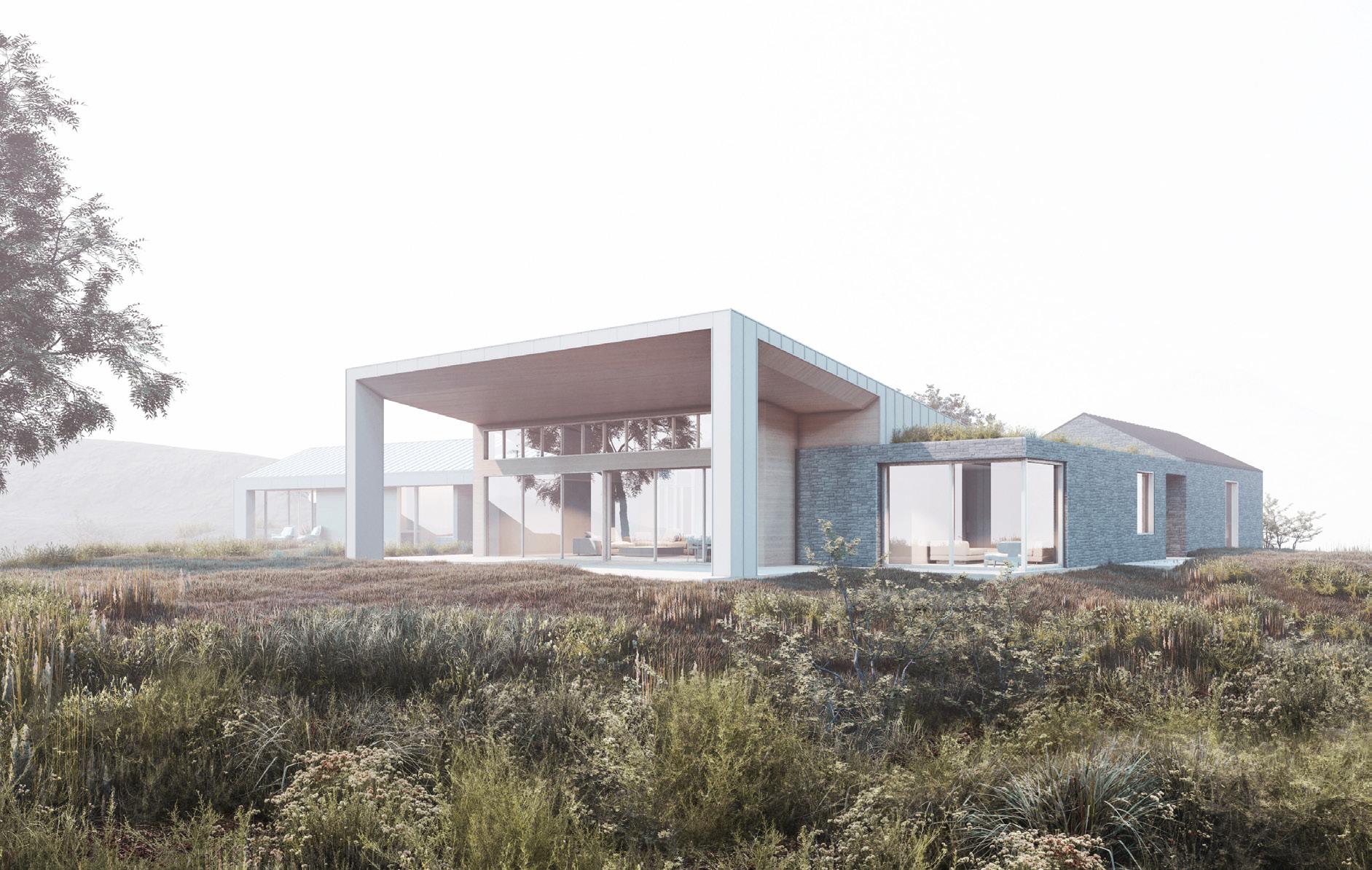
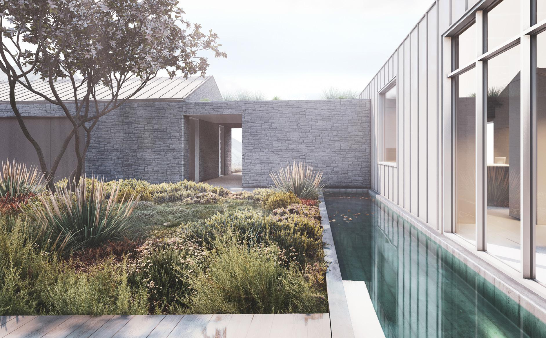
The Canyon House is a rebuild of a family residence destroyed by the 2018 Woolsey Fire. Under the jurisdiction of the Coastal Development Zone, the new residence balances the siting and area restrictions for rebuild projects with the programmatic desires of the client.
By unfolding and consolidating the L-shaped footprint of the previous residence, the new plan improves fire access around the site, maintains a larger clear radius from the site’s protected oak tree, and increases the house’s distance from the ridgeline.
Personal Contribution
• Project Massing, articulation, and finish studies
• Preparation of city planning review exhibits for fire rebuild
• Space planning
• Project modeling, diagramming, and rendering
West Elevation East Elevation Open Patio North Elevation Open Patio South Elevation
Concept Design, SD Otherworks 2019-2020 Malibu, California Single-Family Residence 2,400 sf
West Elevation East Elevation North Elevation South Elevation
36 37 Canyon House 1 2 3 4 5 6 7 8 8 9 10 11 16 12 13 14 15 Entry Living Kitchen/Dining Pantry Office Restroom Den Bedroom Powder Room Master Suite Dressing Room Garage Laundry Storage Dog Run Courtyard 1 2 3 4 5 6 7 8 9 10 11 12 13 14 15 16
View of Back Deck
from Entry
View Towards
Garage
Palm Springs Park
Project Description
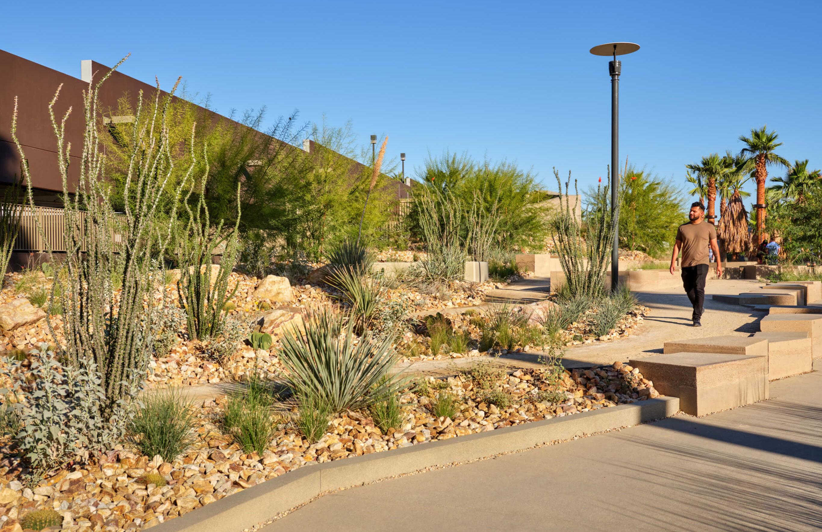
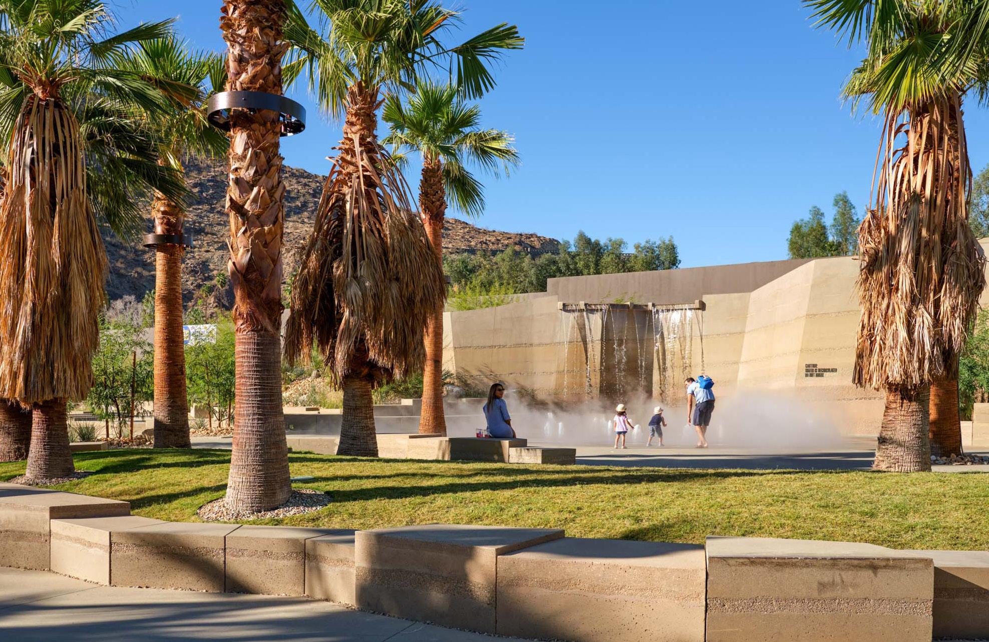
Palm Springs Downtown Park is a 1.54acre public park that draws inspiration from the landscapes and canyons surrounding the city. The architecture components of the project include the public restroomsand police substation building, with a shotcrete-finished form that relates to the geologically-inspired seating and water feature within the park. A stage canopy in the Theater zone of the park echoes the layered effect of palm fronds with its modular composition and perforated aluminum panels.
Personal Contribution
• Design and detailing of substation building and stage canopy
• Coordination with structural engineers and concrete fabricators on customized shotcrete building finish
• Project documentation from Schematic Design to Construction Documents
• Produced presentations for city client and community review
39
Concept Design, SD, DD, CD Rios 2018-2019 Public Park 64,000 sf Police Substation, Restrooms 2,300 sf Event Stage Canopy 940 sf
41 1 2 3 +16'-11" T.O. PARAPET +16'-0" PARAPET 8'-0" T.O. DOOR HEADER +0'-0" FINISH FLOOR 2 A4.11 1 A4.12 1 A4.11 LINE OF ROOF BYND (EX) GARAGE STRUCTURE 4 SOUTH ELEVATION - RESTROOMS AND SUBSTATION 2 Scale: 1/4" = 1'-0" 15 6 A5.04 4 A5.04 LINE OF CMU WALL BYND LINE OF CMU WALL BYND ALUM. PERFORATED PANEL PER SCHED., CUSTOM PATTERN LINE OF ROOF BYND RESTROOM SIGNAGE (SEE GRAPHICS SHEET L9.23) 10 6 A5.03 5 A5.03 4 A5.03 3 A5.03 2 A5.03 1 A5.03 FRITTED GLAZING PER SCHED. +15'-6" T.O.WALL OBLIQUE VIEW OBLIQUE VIEW OBLIQUE VIEW W-2 W-6 W-5 W-4 W-3 10'-0" T.O. WINDOW HEADER TO LANDSCAPE DWG. SHEET L5.09 FOR WALL ELEVATIONS 5% SLOPE 5% SLOPE SEDIMENTARY SHOTCRETE VENEER. SEE LANDSCAPE DWGS. 110.1 111.1 112.1 113.1 KEYNOTES PLANTER (SEE LANDSCAPE DWG) EXTERIOR PAVING (SEE LANDSCAPE DWG) 1 2 3 4 5 6 7 8 9 10 12 13 14 15 PROPERTY LINE COMPACTED SUBGRADE FILL (SEE LANDSCAPE DWG) (EX) PARKING STRUCTURE WALL (EX) PARKING STRUCTURE COLUMN SWITCHGEAR (SEE ELECTRICAL DWG) 4.9% SLOPED WALKWAY 4" CONCRETE SLAB ON GRADE (SEE STRUCT. DWG) WATER FEATURE WALL (SEE LANDSCAPE DWG) 1. A LICENSED ENGINEER OR SURVEYOR SHALL STAKE THE PROPERTY CORNERS OF THE SUBJECT LOT. AT THE TIME OF THE UNDERGROUND PLUMBING INSPECTION, AND PRIOR TO CALLING FOR ANY FOOTING INSPECTIONS FOR THESE PROJECTS, THE CONTRACTOR SHALL PROVIDE STRING LINES ALONG THE PROPERTY LINES ADJACENT TO THE PROPOSED WALL LINES OF THE NEW CONSTRUCTION. 2. PROVIDE ANTI-GRAFFITI COATINGS TO ALL EXPOSED SURFACES PER SPECIFICATIONS 3. ALL STRUCTURAL STEEL TO RECEIVE SURFACE PREP CONSISTENT W/ SSPC SP-6 4. ALL STRUCTURAL STEEL TO RECEIVE DUPLEX PAINT SYSTEM PREP CONSISTENT W/ ASTMD6386 5. ALL STRUCTURAL STEEL TO RECEIVE DUPLEX PAINT GENERAL NOTES CUSTOM MILLWORK CUSTOM SERVICE COUNTER W/ TRANSACTION WINDOW TORCH-DOWN ROOF PER SCHED. WITH DECORATIVE GRAVEL(SEE LANDSCAPE DWG) ANODIZED ALUMINUM PLATE AT JAMB ROOF DRAIN AND OVERFLOW ROOF DRAIN (SEE M1.1) 20 EXHAUST ROOF HOOD (SEE M1.1) 21 VRF OUTDOOR UNIT (SEE M1.1) 22 VENT THROUGH ROOF (SEE M1.1) 23 WATER HEATER (SEE P1.1) 24 SECURITY FENCE (SEE LANDSCAPE DWG) 25 CMU RETAINING WALL (SEE STRUCT. DWG) 26 TACTILE PAVERS (SEE LANDSCAPE DWG) 27 EXHAUST FAN (SEE M1.1) 28 11 WATER FEATURE (SEE LANDSCAPE DWG) 16 EVENT STAGE (SEE LANDSCAPE DWG) 17 (EX) STAIR TO PARKING STRUCTURE (SEE LANDSCAPE DWG) 18 EVENT LAWN (SEE LANDSCAPE DWG) (EX) CURB RAMP (SEE LANDSCAPE DWG) 19 AT LOW POINT 15 15 15 17021 Palm Springs, California 3101 W EXPOSITION PLACE LOS ANGELES, CA 90018 PH: 323.785.1800 FAX: 323.785.1801 rchstudios.com Palm Springs Downtown Park LIC S D EN E ARCHIT TEC CAL MARK W. RIOS C015744 EXP 3-31-21 FORNIA OF STATE MODULE M2 2 A1.21 3 A1.21 PERFORATED ALUMINUM PANEL, CUSTOM PATTERN M2 M2 M2 M1 M3 M3 M1 M1 M1 1A 1B 1C 1D 1E 1A 1B 1C 1D 1E 1A 1B 1C 1D 1E 1A 1B 1C 1D 1E 2A 2B 2C 2D 2E 2A 2B 2C 2D 2E 2A 2B 2C 2D 2E 3A 3C 3D 3E 3B 3A 3C 3D 3E 3B HSS COLUMN PER STRUCTURAL, PTD., AESS 3 STEEL PTD. STEEL FRAME PER STRUCTURAL, AESS 3 STEEL ALIGN ALIGN ALIGN ALIGN ALIGN MODULE M1 MODULE M3 ALIGN 8'-8 1/2" 18'-0" 28'-3 1/2" 7'-5" 12'-0" 7'-5" 10'-3" 36° 36° 36° 144° 36° 36° 65'-2 1/2" 6'-11" 3 A5.10 2 A5.10 1A5.10 0'-0" 0'-0" 0'-0" 0'-0" 0'-0" 0'-0" 0'-0" 0'-0" 0'-0" 0'-0" 0'-0" 0'-0" -0'-7 1/2" -1'-1/2" -0'-7 3/4" -0'-7 1/2" -0'-7 1/2" -1'-1/2" +0'-7 3/4" +1'-1/2" +0'-7 1/2" +0'-7 3/4" +0'-11 3/4" +1'-1/2" +0'-7 3/4" +0'-7 3/4" +0'-7 3/4" +0'-7 1/2" 0'-0" 6 A5.10 5 16 18 17 19 8 1 A C B D 2 3 PLAN - SHADE CANOPY AT EVENT STAGE 1 Scale: 1/4" 1'-0" EVENT LAWN (EX) UNDERGROUND PARKING GARAGE PARK SCOPE OF WORK PRE-CAST CONCRETE SEAT WALL TYP. (EX) UNDERGROUND PARKING GARAGE (EX) PARKING GARAGE (EX) STRUCTURAL COLUMN ADDITIONAL STEEL BEAM REINFORCEMENT REFER TO STRUCTURAL ENGR. DWGS. (EX) STRUCTURAL SLAB (EX) PARKING GARAGE (EX) DRIVE RAMP TO BE DEMOLISHED AND FILLED REFER TO STRUCTURAL ENGR. DWGS. C.I.P. CONCRETE WALKWAY OUTCROP AMPHITHEATER MOUNDED PLANTING AREA DG-1 W-1 DG-1 PAV-1 PRE-CAST CONCRETE SEAT WALL TYP. W-1 SLOPED LAWN 3 L5.03 3 L5.03 STRUCTURAL FOAM FILL ABOVE UNDERGROUND PARKING GARAGE REFER TO STRUCTURE ENGR. DWGS. SUBSURFACE DRAINAGE REFER TO CIVIL ENGR. DWGS. (EX) WATERPROOFING MEMBRANE TO REMAIN DRAINAGE SWALE REFER TO CIVIL DWGS. ALIGN CMU RETAINING WALL REFER TO SHEET L4.01 DETAIL 3 FOR EXTENT VARIES W-6 AMENDED PLANTING SOIL REFER TO PLANTING DETAILS & SPECIFICATIONS EVENT STAGE MUSEUM WAY SHADE CANOPY STRUCTURE SEE ARCH. DWGS. (EX) UNDERGROUND PARKING GARAGE C.I.P. CONCRETE WALKWAY PARK SCOPE OF WORK (EX) C.I.P. CONCRETE CURB PAV-1 PAV-1 HR-1 PAV-1 PAV-1 (EX) STRUCTURAL COLUMN ADDITIONAL STEEL BEAM REINFORCEMENT PER STRUCTURAL ENGR (EX) STRUCTURAL SLAB STRUCTURAL FOAM FILL ABOVE UNDERGROUND PARKING GARAGE REFER TO STRUCTURE ENGR. DWGS. SUBSURFACE DRAINAGE REFER TO CIVIL ENGR. DWGS. (EX) WATERPROOFING MEMBRANE TO REMAIN CANOPY COLUMN FOOTING REFER TO STRUCTURAL ENGR. DWGS. STAIR FOOTINGS REFER TO STRUCTURAL ENGR. DWGS. PATCH & REPAIR EXISTING WATERPROOFING AS NEEDED REFER TO SHEET WP0.01 STAGE FOOTINGS REFER TO STRUCTURAL ENGR. DWGS. W-3 PATCH & REPAIR EXISTING WATERPROOFING AS NEEDED REFER TO SHEET WP0.01 OVERALL SITE SECTION - EVENT STAGE OVERALL SITE SECTION LANDFORM MATCHLINESEE ABOVE FINISHED FLOOR GROUND 1'-6" EVENT STAGE LEVEL STRUCTURAL SLAB BELOW (ABOVE F.S.) STRUCTURAL SLAB BELOW
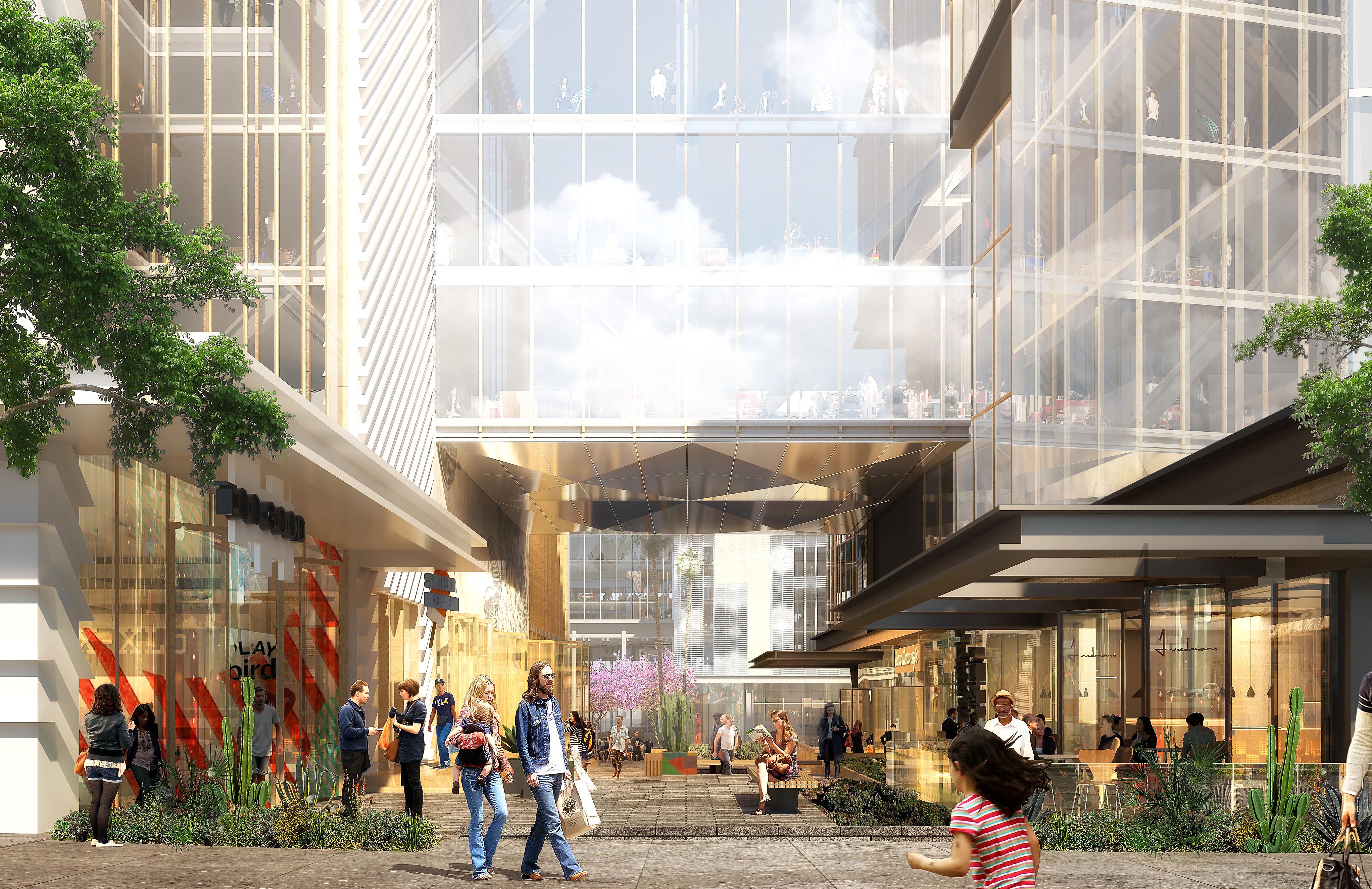
Undisclosed: San Diego Office Competition
Project Description
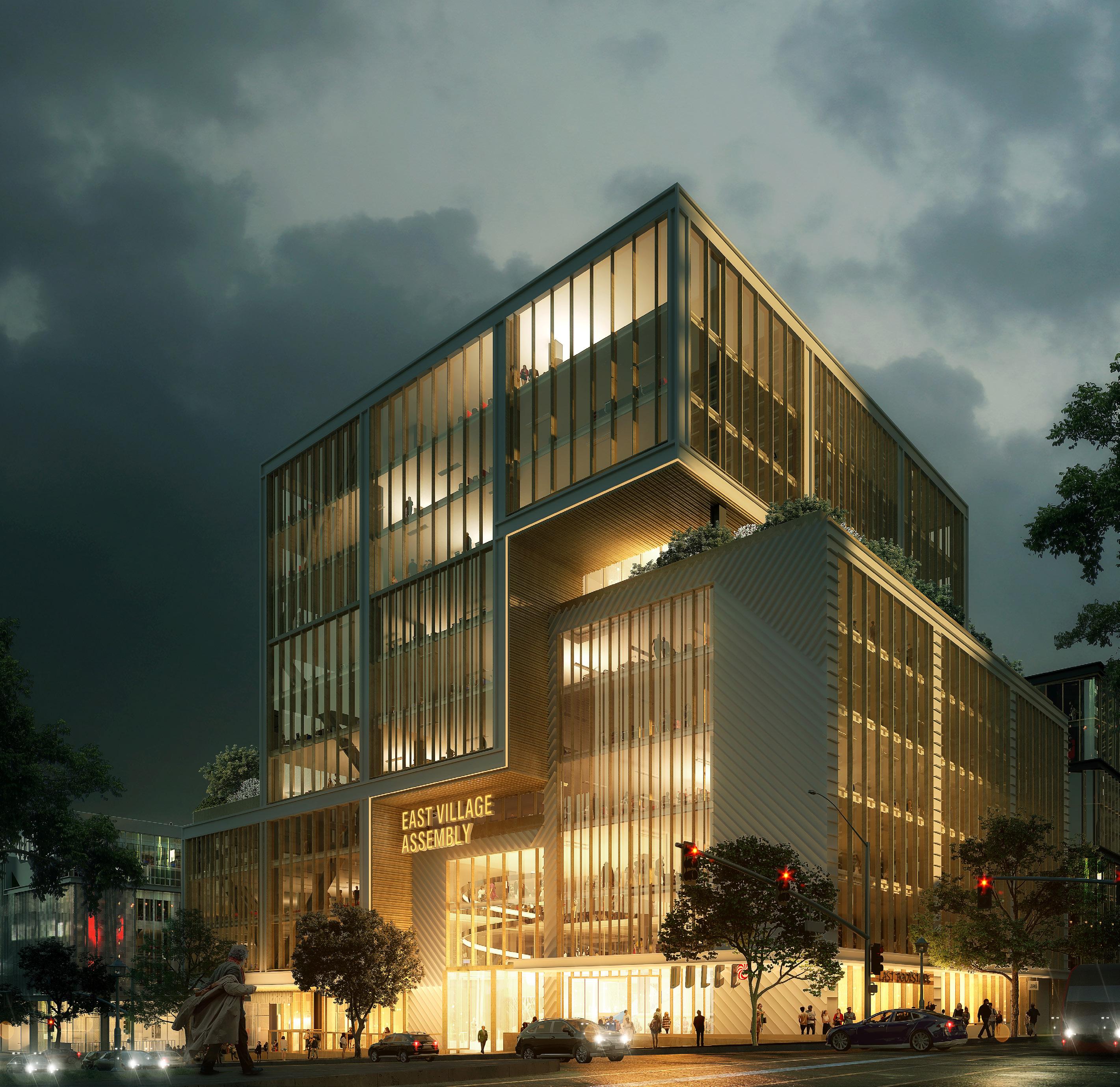
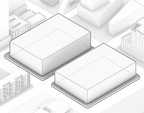
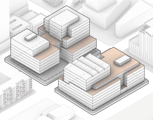
As part of an invited competition, Otherworks developed a proposal for a new urban center in a developing neighborhood. Spanning two blocks, the project is situated at the junction of existing mid-rise residential and future residential tower development. Flexibility and optionality for both the owner and the future tenant are key to the workplace design strategy of the project. Adaptable to both single and multi-tenant configurations, the project is designed to function at all scales.
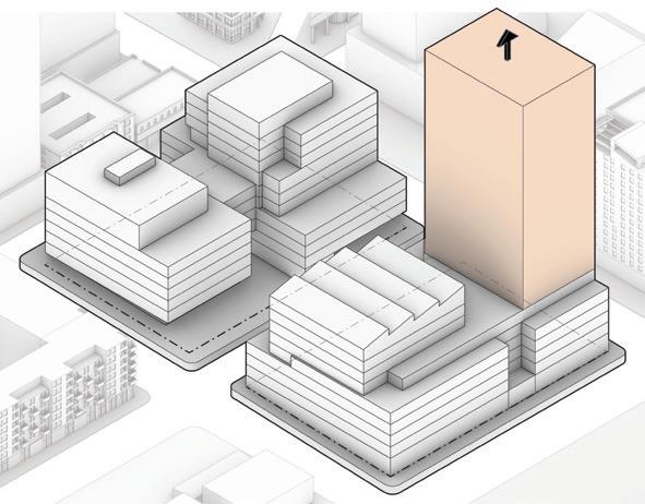
The West block forms a gateway to the site, creating a mid-block passage to connect to the local public transit station. The East block bookends the project. Tower plates create opportunities for opening up the ground plane, and a series of decks wrap strategically located amenity levels. In the event that the owner opts to introduce a residential program, a position at the northeast corner of the building has been configured to receive the tower.
Personal Contribution
• Massing and Facade articulation studies
• Project modelling, diagramming, drawing, and rendering for client review and competition
• Groundscape, retail, and food hall planning and design
43
Invited Competition Otherworks 2020 San Diego, California Office / Retail 750,000 sqft
East and West Blocks
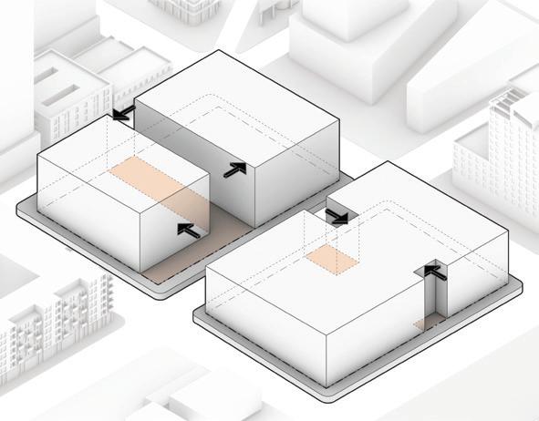
The West block forms the gateway to the site, while the East block becomes the bookend of the project.
Plaza and Courtyards
Bisecting the Western block, a midblock passage connects to the trolley line while maintaining a sense of seperation. A plaza at the corner of 13th and E St is the anchor public space of the project.
Office Towers
Tower plates create opportunities for opening up the ground plane. Positioned on opposing corners of the site, the major towers maintain viewplanes outward.
Deck Connections
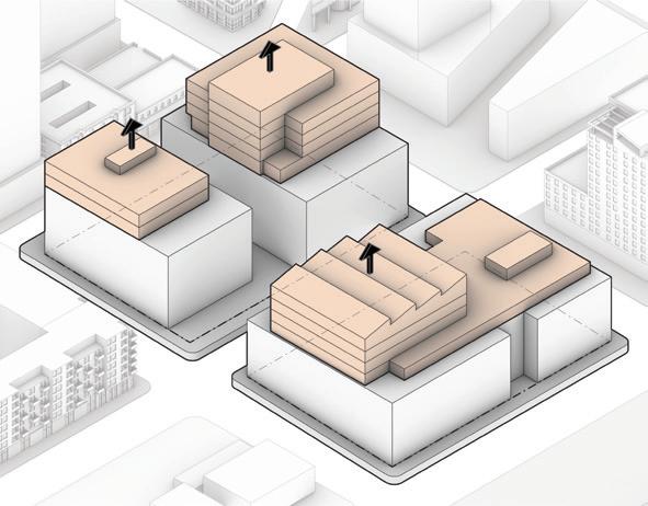
A series of decks wrap the upper office plates and are tied to strategically located amenity levels.
Residential Tower
In the event that the owner opts to introduce a residential program, a position at the corner of 13th and Broadway has been configured to receive the tower.
44 45 East Village Competition
Massing Process N 1 2 1 6 4 5 3 Core Services Open Office Conference Rooms Breakout Spaces Cafeteria/Amenity Office Deck 1 2 3 4 5 6
