10 minute read
HIGH-PERFORMANCE HVAC Creating tighter duct systems: An efficient strategy
CREATING TIGHTER DUCT SYSTEMS:
An efficient strategy
While preparing for a training program on the compelling history of energy efficiency improvements in Canadian homes over the last 30 years, I was reminded of a Natural Resources Canada (NRCan) initiative from back in 2004 to optimize the energy used specifically for the distribution of air in new and existing homes. It was recognized at the time that the electrical consumption of furnace fan motors was by no means as significant as the space heating or cooling energy consumption in homes. None the less, I was asked to facilitate an industry forum that established some long-term objectives to optimize electrical use of fans in HVAC systems. There were several initiatives proposed from the forum. The first was to reduce the overall capacity of heating and cooling systems by ensuring more accurate sizing of equipment. The outcome was the re-write of the CAN/CSA F280-12 Standard (Determining the Required Capacity of Residential Space Heating and Cooling Appliances). This was completed in 2012 and systems designed to the new standard are 30 to 40 per cent smaller on average than under the old standard. The second initiative was to improve fan motor efficiency. This has been accomplished as of 2019 with a very specific Fan Efficiency Rating (FER) regulation in North America that ensures either electronically commutated or constant torque fan motors are used in residential air handling equipment. The third initiative was to reduce overall air delivery needs by generally promoting energy efficiency in homes but also by reducing duct leakage. As far back as the early 1990s, duct leakage studies, primarily in the U.S., showed that as much as 20 per cent of the total system airflow was lost through duct work leaks before reaching supply outlet grilles, and as much as 50 per cent of return airflow was drawn through duct leaks rather than from the return grilles. It is important to acknowledge that the focus of U.S. studies was on duct systems installed in unconditioned spaces such as attics and crawlspaces whereby duct leakage resulted in a significant direct energy loss. By contrast, a 2002 study I completed for a large gas utility in southern Ontario on 60 homes (30 new construction and 30 older homes), found that supply duct leakage on typical sheet metal duct systems was never less than 20 per cent and averaged 25 to 35 per cent. It shouldn’t be a surprise, given that it is most common in Canada to use joist or stud-lined cavities for much of the return duct system. Return duct leakage was so high, over 50 per cent, it hardly made sense to even try and measure or seal it. Unlike the U.S., most of the duct work in Canadian homes is located in conditioned space and thus there is an assumption that the duct leakage isn’t a direct energy loss to outside. However, in the 2002 study, in half of the houses studied, as much as five per cent of the duct leakage was found to be to the outside. In some cases, this was because there were ducts in unconditioned spaces such as ceilings over garages or in boxed in cavities adjacent to outside walls. In other cases, it was simply that the stud-lined cavities used for return air pathways, such as for high wall returns in upper floor bedrooms, were not thoroughly air sealed at the top plate of the wall to the attic. Even without direct duct leakage to outside, there are energy penalties connected to duct leakage in Canadian homes. The additional fan motor power to deliver the additional 25 per cent of air needed to compensate for duct leakage was estimated by
A powered flow hood is used to accurately measure airflow from each supply register in a home.
Gord Cooke Gord is a professional engineer who has spent 35 years helping builders and HVAC contractors implement innovative technologies into high-performance homes. He has particular expertise in IAQ and airflow management in houses, and can be contacted at gordc@buildingknowledge.ca.

the NRCan initiative to be between two and 12 per cent of the electrical consumption of air distribution systems. The more compelling issue in my mind is the extra energy wasted to compensate for duct leakage to meet the comfort expectations of today’s homeowners. When the room over the garage is too cold in winter and too hot in summer due in part to the duct leakage resulting in inadequate flows to those types of rooms, homeowners and their HVAC contractors compensate by increasing fan speeds and heating and cooling capacity. Creating tighter duct systems is a more efficient strategy for solving these comfort issues.
Much of the ductwork used in U.S. applications was insulated flexible duct with a much lower air leakage potential than the sheet metal systems more commonly used in Canada.

Quantifying DUCT LEAKAGE
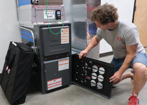
Typically, a pressure of 0.1 in. of water column or 25 Pascal is used as this is a common average pressure residential duct systems operate at. The flow needed to maintain that pressure is reported to be the duct leakage. This rate can be expressed as a ratio or percentage of the total flow of the system, if it is known. For example, it is common to assume a twoton air conditioning system operates at a flow of 800 cubic feet per minute (400 CFM per ton). If the calibrated fan used to maintain a pressure in the duct to 0.1-in. w.c. has a flow of 100 CFM, then the duct leakage would be expressed as 100/800 or 12.5 per cent duct leakage. In the U.S., approximately 30 states have building codes requiring duct leakage verification. The testing is typically done, not by HVAC contractors, but by specialized contractors known as Energy Raters and the testing is often done at the rough-in stage. Since the Energy Rater wouldn’t necessarily have knowledge of the capacity of the heating and cooling system and its design airflow, a different metric is used. The flow required to create the 0.1-in. w.c. pressure in the duct is expressed as the leakage airflow per 100 sq. ft. of the conditioned floor area of the house. For example, in a 2,000-sq. ft. house There are two common methods used to quantify duct leakage. The first is to the duct leakage rate would be 100 CFM measure or calculate the total airflow at the furnace or air handler and compare it of leakage divided by 20 (the 20 is derived to the sum of the delivered airflow to each supply grille. The comparison can be from taking the 2,000 sq. ft. of floor area and expressed as a percentage of the presumed duct leakage to the total flow. dividing it by 100) to arrive at 5 CFM per 100 Knowing or estimating the flow at the furnace can be done by taking total static sq. ft. of conditioned floor area. In the 2012 pressure readings across the furnace, including the filter and the air conditioning International Energy Conservation Code the coil in the measurements. Then refer to the technical data specifications for the maximum duct leakage rate allowed is 3 appliance and use the fan curves or tables to determine CFM/100SF at the rough-in stage. the flow. With electronically commutated fan motors, I have found this method to be reasonably reliable. However, in my opinion, it is quicker and even more reliable to use one of the proprietary duct flow measurement devices now available to take direct airflow readings right at the appliance. There are flow grids which can be inserted into the filter slot or a calibrated fan assembly mounted in place of the blower cabinet door that provide very accurate total flow measurements within a few minutes. Getting results of the accumulated flows at individual supply grilles requires a flow capture hood, such as a balometer capture hood, for meaningful duct leakage results. Estimating flows by taking velocity readings with an anemometer at each supply grille, in my experience, offers too many opportunities for accumulated errors to be reliable for duct leakage determination specifically. The second method, commonly used in the U.S., is to temporarily seal each supply grille and then pressurize the duct system with a calibrated fan to a known fixed pressure. Technology available today can provide a simple and accurate measurement of airflow through residential air handlers.

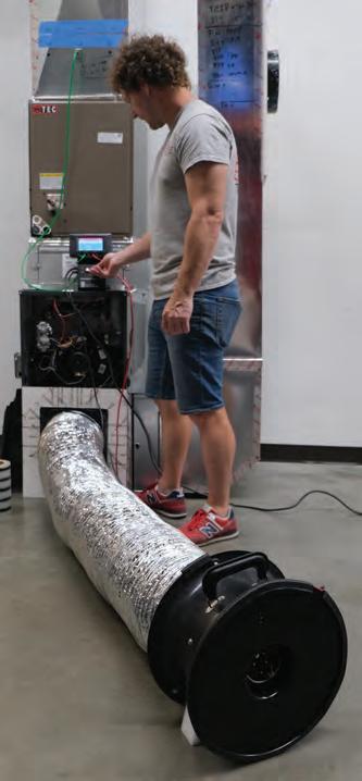
It has been a building code requirement in Ontario since 2014 for all supply ducts to be sealed to a Class C level as defined by the SMACNA HVAC Duct Construction Standards. Class C calls for all the transverse joints of supply ducts to be sealed with mastic or approved tapes. Our measurements have shown that as a result of this sealing, new homes now have supply duct leakage rates averaging 10 to 15 per cent. Certainly, a nice improvement. However, if a room is receiving 15 per cent less air than design, logically the room might be 15 per cent warmer on a hot summer day than intended. In my warranty investigation work, I still find it very difficult to explain to uncomfortable new home buyers that one of the reasons their master bedroom is 2ºC warmer than the main floor on a hot summer day is due to this “average” duct leakage. Fortunately, all professional HVAC contractors can assess duct leakage with the right equipment in as little as 45 minutes. While the 2004 NRCan initiatives noted addressing duct leakage in new construction would be “realistic,” the report suggested it would be “difficult to implement in existing homes.” This is no longer the case in 2022. There is wide acceptance and availability of the proprietary aerosolized duct sealing technology that can be applied to almost any house in Canada. In my own home, which was built in 1993, I had been successful in taping and sealing joints to get down to 19 per cent duct leakage, as a percentage of total system flow. More recently, after 28 minutes of application of the aerosolized duct sealing technology, the leakage rate was reduced to three per cent. Most importantly the flow to critical rooms at the “end of the line” was improved by over 20 per cent. I was able to rebalance airflow to all rooms with precision. I was also able to select a lower fan speed setting on the variable flow air handler and the power draw from the fan motor was reduced by 25 per cent − just as the 2004 NRCan initiative imagined. In my mind this is another compelling example of the day-to-day opportunities HVAC contractors have in applying Canadian research and the resulting technological improvements to simultaneously improve comfort and energy efficiency for clients. A duct blaster is used to directly pressure test the duct system for air leaks.

SD SERIES
Standard Exhaust Fans
YYr One Stt Sht ff all of yYr Wall Fan needs
XFS SERIES
Exhaust Shutter Fans
AX SERIES


Shutter Mounted Fans


www.canarm.com hvacsales@canarm.ca 1-800-267-4427


