2 minute read
Overvoltage Protection for Remote Bus Lines (Lightning protection


Overvoltage Protection for Remote Bus Lines (Lightning protection)
Overvoltage Protection To protect the transmission equipment from coupled voltage spikes (lightning strike), overvoltage protection equipment should be used in the remote bus cables, as soon as it is laid outside of buildings. The nominal discharge current should, in this case, be at least 5kA. The lightning arrestors Type VT RS485 and Type CT B110 from Dehn und Söhne GmbH & Co KG can, for example, be used. For the supplier address and order numbers for protection equipment and accessories, see TSX Momentum, Bus Adapter for INTERBUS, User Manual. To protect an INTERBUS cable, two protection device groups are required in each building. The first group (Type B110) is positioned where the cable enters the building and is used as the lightning conductor. The second group (Type RS485), close to the first node, is the overvoltage protection device.
Advertisement
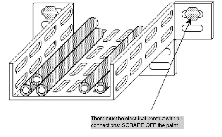
Connection Rules for Protection Devices Before connection of the protection devices please observe the following rules. Install a functional ground (equipotential bonding rail). Assemble the protection devices near the building ground, so that the overload current is diverted along the shortest route. The cable (minimum 6mm2) to the building and functional ground should be as short as possible. A maximum of 10 protection devices connected in series with 4 open land sections, for connecting buildings to each other, are allowed in the INTERBUS cables. Perform a Shield grounding (seepage308) of the INTERBUS lead according to the lightning arrestor used (type CT B110 or type VT RS485).
Protection Device Connection Plan
Type and number of the lightning arrestors from Dehn und Söhne GmbH &Co KG for a remote bus cable LiYCY (INTERBUS):
NOTE: Information about assembly and connection of the cables can be found in the relevant installation instructions that come with lightning arrestor.
No. Type Number per Group
1 VT RS485 1
2 CT B110 3
Shield Grounding with Protection Devices Direct or indirect shield grounding are offered by the protection devices. An indirect grounding occurs using gas conductors. The construction of the shield grounding depends on the type of lightning arrestor.
NOTE: Further information about grounding and shield grounding can be found in the relevant installation instructions that come with the lightning arrestor.
Lightning Arrestor Type Direct Shield Grounding
CT B110 Connect the shield of the incoming remote bus cable at connection IN and that of the remote bus cable at connection OUT. The shields are now galvanically connected with PE. Indirect Shield Grounding Using Gas Conductors
Connection of the shield as described for direct shield grounding. Put the gas conductor in the unit underneath the shield connection terminal on the input side.
EMC cage clamp terminals fasten the remote bus cable shield on the input and output sides.
VT RS485 Connect the shield of the incoming remote bus cable at connection IN2 and that of the remote bus cable at connection OUT2. Connect the shield of the incoming remote bus cable at connection IN1, and the remote bus cable shield at connection OUT1. The gas conductor is installed in the device.
Note: Connect the grounding terminals of the lightning arrestor to the PE.