
5 minute read
Product Description Produktbeschreibung


FMS Koaxialkontakte, 50 Ohm, gerader Kabelanschluss, Pindurchmesser 0,75mm
Platings and Order Information Oberflächen- und Bestell-Informationen
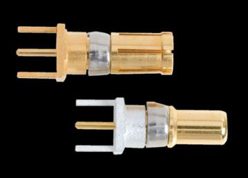
FME Koaxialkontakte mit Leiterplattenanschluss
Advantages and Special Features n Coaxial contact 50 Ohm/75Ohm design n Straight and right angled construction n PCB termination with 3 and 5 pins n PCB hole patter n see page 212 onwards n Recommended for FCT mixed layout connectors

Vorteile und Merkmale im Überblick
FME Coaxial Contacts, 50 Ohm, Straight PCB Termination, 3 Pins
Dimensions of an Example Connector with Coaxial Contact FME010P and Signal Contacts P1
Product Description Produktbeschreibung
FME Koaxialkontakte, 50 Ohm, gerader Leiterplattenanschluss, 3 Anschlüsse
Abmessungen am Beispiel Steckverbinder mit Koaxialkontakt FME010P und Signalkontakten P1
Dimensions Abmessungen
Pin Stecker
Platings and Order Information Oberflächen- und Bestell-Informationen
FME Coaxial Contacts, 50 Ohm, Right Angled PCB Termination, 3 Pins
Dimensions of an Example Connector with Coaxial Contacts FME008P or FME020P and Signal Contacts P5
Product Description Produktbeschreibung
FME Koaxialkontakte, 50 Ohm, abgewinkelter Leiterplattenanschluss, 3 Anschlüsse
Abmessungen am Beispiel Steckverbinder mit Koaxialkontakten FME008P oder FME020P und Signalkontakten P5
Platings and Order Information Oberflächen- und Bestell-Informationen
FME Coaxial Contacts, 50 Ohm, Right Angled PCB Termination, 5 Pins
Dimensions of an Example Connector with Coaxial Contact FME009P and Signal Contacts P45
Dimensions Abmessungen
Product Description Produktbeschreibung
FME Koaxialkontakte, 50 Ohm, abgewinkelter Leiterplattenanschluss, 5 Anschlüsse
Abmessungen am Beispiel Steckverbinder mit Koaxialkontakt FME009P und Signalkontakten P45
Pin Stecker
Platings and Order Information Oberflächen- und Bestell-Informationen
Fme
Fme
FME Coaxial Contacts, 75 Ohm, Straight PCB Termination, 3 Pins
Dimensions of an Example Connector with Coaxial Contacts FME005P... and Signal Contacts P1
Product Description Produktbeschreibung
FME Koaxialkontakte, 75 Ohm, gerader Leiterplattenanschluss, 3 Anschlüsse
Dimensions Abmessungen
Pin Stecker
Platings and Order Information Oberflächen- und Bestell-Informationen
Abmessungen am Beispiel Steckverbinder mit Koaxialkontakt FME005P... und Signalkontakten P1 Socket Buchse
FME Coaxial Contacts, 75 Ohm, Right Angled PCB Termination, 3 Pins
Dimensions of an Example Connector with Coaxial Contacts FME001P (Shell Sizes 1 - 4) or FME018P and Signal Contacts P5
Dimensions Abmessungen
Product Description Produktbeschreibung
Pin Stecker
Platings and Order Information Oberflächen- und Bestell-Informationen
Fme
Koaxialkontakte,
75 Ohm, abgewinkelter Leiterplattenanschluss, 3 Anschlüsse
Abmessungen am Beispiel Steckverbinder mit Koaxialkontakten FME001P (Gehäusegröße 1 - 4) oder FME018P und Signalkontakten P5
Buchse
FME Coaxial Contacts, 75 Ohm, Right Angled PCB Termination, 5 Pins
Dimensions of an Example Connector with Coaxial Contact FME002P and Signal Contacts P45
Dimensions Abmessungen
Product Description
Produktbeschreibung
FME Koaxialkontakte, 75 Ohm, abgewinkelter Leiterplattenanschluss, 5 Anschlüsse
Abmessungen am Beispiel Steckverbinder mit Koaxialkontakt FME002P und Signalkontakten P45
Pin Stecker
Socket Buchse
Platings and Order Information Oberflächen- und Bestell-Informationen
FME …010P, 005P FME …010P, 005P
PCB Hole Pattern for Connectors with Straight PCB Terminations
All PCB hole patter ns apply to male connectors with straight PCB contacts (signal contacts P1) and the coaxial contacts FME010P or FME005P (when using female connectors the hole patter n must be mirrored on the Y-axis) Measurements without tolerances are in accordance with DIN ISO 2768 m
Technical Details
Technische Hinweise
Leiterplattenlochbild für Steckverbinder mit geradem Leiterplattenanschluss
Alle Lochbilder gelten für Stiftsteckverbinder mit geradem Leiterplattenanschluss (Signalkontakte P1) und eingebauten Koaxialkontakten FME010P bzw FME005P (bei Verwendung von Buchsensteckverbindern muss das Lochbild an der Y-Achse gespiegelt werden) Maße ohne Toleranzangabe nach DIN ISO 2768 m
FME …010P, 005P
FME …010P, 005P
PCB Hole Pattern for Connectors with Straight PCB Terminations
All PCB hole patter ns apply to male connectors with straight PCB contacts (signal contacts P1) and the coaxial contacts FME010P or FME005P (when using female connectors the hole patter n must be mirrored on the Y-axis) Measurements without tolerances are in accordance with DIN ISO 2768 m
Technical Details
Technische Hinweise
Leiterplattenlochbild für Steckverbinder mit geradem Leiterplattenanschluss
Alle Lochbilder gelten für Stiftsteckverbinder mit geradem Leiterplattenanschluss (Signalkontakte P1) und eingebauten Koaxialkontakten FME010P bzw FME005P (bei Verwendung von Buchsensteckverbindern muss das Lochbild an der Y-Achse gespiegelt werden) Maße ohne Toleranzangabe nach DIN ISO 2768
PCB Hole Pattern for Connectors with Straight PCB Terminations
All PCB hole patter ns apply to male connectors with straight PCB contacts (signal contacts P1) and the coaxial contacts FME010P or FME005P (when using female connectors the hole patter n must be mirrored on the Y-axis) Measurements without tolerances are in accordance with DIN ISO 2768 m
Leiterplattenlochbild für Steckverbinder mit geradem Leiterplattenanschluss
Alle Lochbilder gelten für Stiftsteckverbinder mit geradem Leiterplattenanschluss (Signalkontakte P1) und eingebauten Koaxialkontakten FME010P bzw FME005P (bei Verwendung von Buchsensteckverbindern muss das Lochbild an der Y-Achse gespiegelt werden) Maße ohne Toleranzangabe nach DIN ISO 2768 m
FME …010P, 005P
FME …010P, 005P
PCB Hole Pattern for Connectors with Straight PCB Terminations
All PCB hole patter ns apply to male connectors with straight PCB contacts (signal contacts P1) and the coaxial contacts FME010P or FME005P (when using female connectors the hole patter n must be mirrored on the Y-axis) Measurements without tolerances are in accordance with DIN ISO 2768 m
Technical Details Technische Hinweise
Leiterplattenlochbild für Steckverbinder mit geradem Leiterplattenanschluss
Alle Lochbilder gelten für Stiftsteckverbinder mit geradem Leiterplattenanschluss (Signalkontakte P1) und eingebauten Koaxialkontakten FME010P bzw FME005P (bei Verwendung von Buchsensteckverbindern muss das Lochbild an der Y-Achse gespiegelt werden) Maße ohne Toleranzangabe nach DIN ISO 2768 m
FME …010P, 005P FME …010P, 005P
PCB Hole Pattern for Connectors with Straight PCB Terminations
All PCB hole patter ns apply to male connectors with straight PCB contacts (signal contacts P1) and the coaxial contacts FME010P or FME005P (when using female connectors the hole patter n must be mirrored on the Y-axis) Measurements without tolerances are in accordance with DIN ISO 2768 m
Technical Details Technische Hinweise
Leiterplattenlochbild für Steckverbinder mit geradem Leiterplattenanschluss
Alle Lochbilder gelten für Stiftsteckverbinder mit geradem Leiterplattenanschluss (Signalkontakte P1) und eingebauten Koaxialkontakten FME010P bzw FME005P (bei Verwendung von Buchsensteckverbindern muss das Lochbild an der Y-Achse gespiegelt werden) Maße ohne Toleranzangabe nach DIN ISO 2768 m
FME …008P, 001P FME …008P, 001P
PCB Hole Pattern for Connectors with Right Angled PCB Terminations
All PCB hole patter ns apply to male connectors with right angle PCB contacts (signal contacts P5) and the metal bracket F108013B as well as the coaxial contacts FME008P or FME001P (When using female connectors the hole patter n must be mirrored on the Y-axis) Measurements without tolerances are in accordance with DIN ISO 2768 m
Leiterplattenlochbild für Steckverbinder mit abgewinkeltem Leiterplattenanschluss
Alle Lochbilder gelten für Stiftsteckverbinder mit abgewinkeltem Leiterplattenanschluss (Signalkontakte P5) und Metallwinkel
F1080–13B sowie eingebauten Koaxialkontakten FME008P bzw FME001P (bei Verwendung von Buchsensteckverbindern muss das Lochbild an der Y-Achse gespiegelt werden)
Maße ohne Toleranzangabe nach DIN ISO 2768 m
PCB Hole Pattern for Connectors with Right Angled PCB Terminations
All PCB hole patter ns apply to male connectors with right angle PCB contacts (signal contacts P5) and the metal bracket F108013B as well as the coaxial contacts FME008P or FME001P
(When using female connectors the hole patter n must be mirrored on the Y-axis) Measurements without tolerances are in accordance with DIN ISO 2768 m
Leiterplattenlochbild für Steckverbinder mit abgewinkeltem Leiterplattenanschluss
Alle Lochbilder gelten für Stiftsteckverbinder mit abgewinkeltem Leiterplattenanschluss (Signalkontakte P5) und Metallwinkel
F1080–13B sowie eingebauten Koaxialkontakten FME008P bzw FME001P (bei Verwendung von Buchsensteckverbindern muss das Lochbild an der Y-Achse gespiegelt werden)
Maße ohne Toleranzangabe nach DIN ISO 2768 m


