7 minute read
Adventures in modelling
After 70 odd years of model boat building, consisting of both power and scale, scratch built and kits, and with most equipped for radio control, I’ve probably built enough vessels to start my own private navy! Because I am one of those modellers who enjoys the building more than the operating (although I raced my own designed I.C. power boats for many years) I get bored very quickly when I don’t have a project on the go, so a constant problem (not least to keep me out of my long-suffering wife’s hair) is what to build next. I was, therefore, intrigued by the interview with Billing Boats run in this magazine last year, explaining how the company has updated its kit manufacturing process to incorporate the very latest in cutting-edge technology into the traditional process.
Consequently, I contacted Billings to enquire about the Calypso, a kit I’d always fancied building but which had been off the market for some time. The news was good, as there were indeed plans to reintroduce the Calypso into the range. Initially, I was informed that the Calypso would be available again in the UK in approximately two months but, to my delight, I had an email just a month later informing me that a consignment of kits had reached UK distributors earlier than had originally been anticipated. After a bit of shopping around, I eventually placed an order with the Model Shop Leeds. The staff were extremely helpful, and my kit was dispatched that very same day. It arrived as promised, perfectly packed, the day after. So, after many years of admiring the full-sized vessel, my build could finally begin.
Owing to restrictions of space, I’ve had to omit some of the construction photos I shot along the way. However, for anyone also thinking of embarking on this build, hopefully the most pertinent aspects of the process are illustrated here. Please excuse the background in some of my photos as I live in a small onebedroom flat with a very compact working area. Also, some of the white spots on my model are still awaiting clean up and, in many cases, more sanding and painting.
Diving in
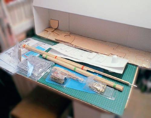
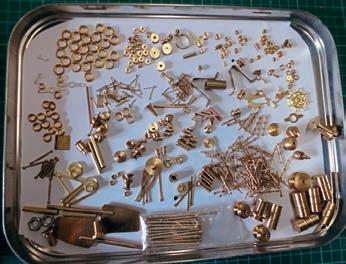
To get started, let’s first take a look at what’s in the box (see Photo 1), although please note that the pre-formed hull included has been removed in this particular shot so as to afford a better view of everything else. The first thing I noticed was that this kit features no white metal parts: all fittings are either beautifully turned brass (see Photo 2) or plastic components, the latter supplied still attached to their sprues. It also needs to be noted that there are no pointto-point assembly instructions; instead, a comprehensive instruction manual features detailed drawings in which components are individually numbered to tally with both a correspondingly numbered parts list and all the directions on the plan provided. I found the brass parts take a little more studying to confidently identify, although, in fairness, that may just be me, as the drawings of them are good.
Not only are all of the above mentioned instructional documents accessible on Billings’ website (www.billingboats.com – just key Calypso into the site’s search engine) but you can also view numerous photographs of both the full-sized prototype the kit is based on and the resulting model on completion, which I found enormously helpful for reference purposes during my build.
Preparing the hull
As always, I started with the hull, firstly trimming off any excess plastic from the ABS molding before fitting the deck supports. As the hull is very flexible, I decided to add two cross braces to strengthen it at this point. I always complete all hardware and electrical work before I even think of fitting or working on the deck, but an essential task before mounting anything in the hull is to ensure you have access for any items to be added later (such as a battery) or indeed so that you can carry out maintenance of the equipment installed. The easiest way of doing this is to remove the deck from the sheet, dry fit it to the hull, and mark the point where your motors and servos are to be fitted.
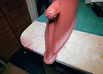
In Photos 3 and 4 you can see the completed external part of the hull, with its underwater primer already applied. Painting would be carried out later, after the decks had been fitted and the hull stabilized. You will observe, however, that at this stage I had fitted the rub rails and deck trim. When fitting the shafts and rudder post, I knew that, because vacuum-formed plastic hull is semi-flexible, epoxy would have proved too brittle and often doesn’t always adhere well (these same failings also apply to superglue). In this instance, therefore, I opted to use an industrial glue gun sourced from Gluegunsdirect in conjunction with a TECBOND 1942 glue stick, thereby ensuring everything would remain firmly adhered and waterproof.
R/C installation
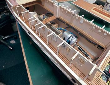
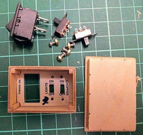
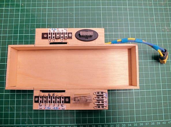
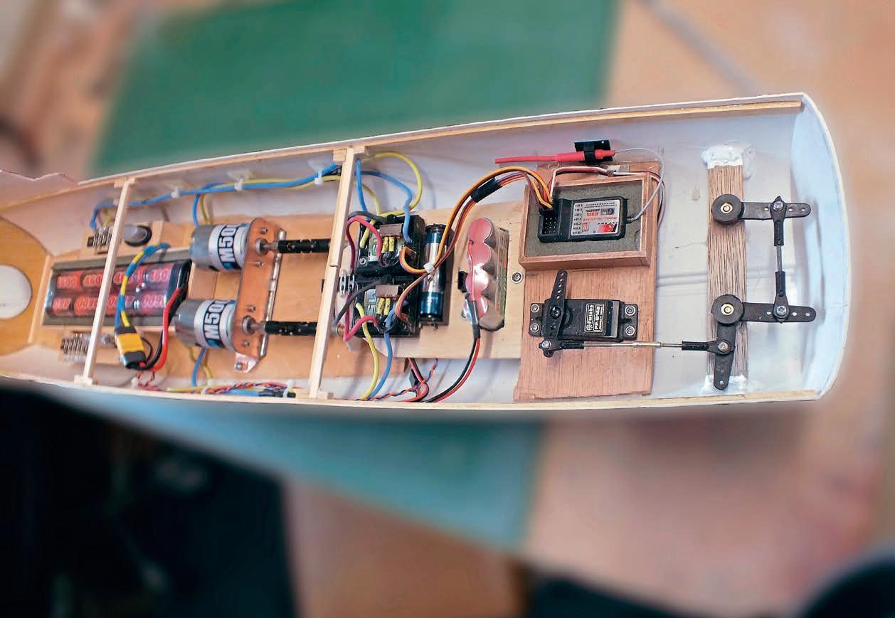
Although the gear itself is not included, this kit is specifically designed with R/C installation in mind. How you decided to equip your model is, of course, entirely up to you.There are many ways to mount motors, and brushed and brushless types often require different solutions. I have used brushless motors in my faster boats but prefer brushed in this type of model (yes. I’m an old ‘stick in the mud’ and far more comfortable with what I know best!). I make most of my engine mounts using a double-sided fiberglass PC board (I find this gives the mountings strength and yet a little flexibility), with the vertical portion aligned and soldered. In my photos you can view the construction and installation of my battery box (Photo 5), modified front deck hatch to mount the on/off switches (see Photo 6) and completed mechanicals and electronics (see Photo 7). You’ll note that apart from the Nimh main battery up forward, there’s 4 x AA rechargeable cells and 1 x AA dry cell. These are for lighting and the rotation of the main rota on the helicopter consecutively.
I’m very fortunate in that my trade was in the electrical and electronics industry, but a very important task, and one that is often sadly overlooked by many modellers, is the accurate lining up of shafts to the motor. Correct alignment gives better performance, less battery current drain, less noise and less wear and tear. A tip if using a double coupling or any flexible coupling is to fit a piece of tubing around the extended coupling, although I’m sure there are many other exceptional methods employed by innovative modelers out there.
Planking the deck
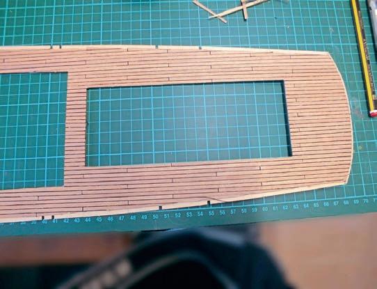
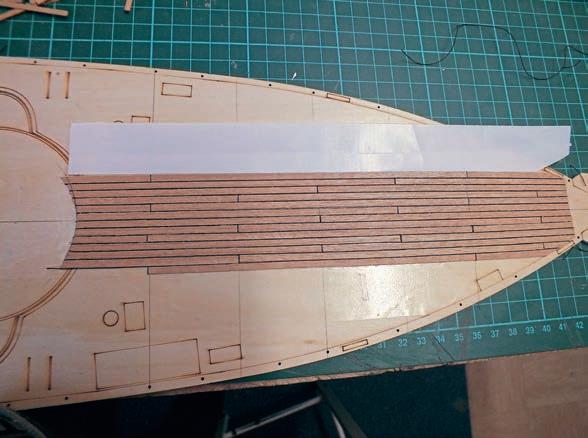
With the internals complete, let’s return to the deck. The kit illustrations show the planking in the length supplied. I, however, chose to plank as I normally do, to the length of the prototype. There’s always controversy when it comes to planking to the correct (albeit scaled down) size but searching the web for the original minesweeper on which the Calypso was based revealed a mine of vastly conflicting information and images, so in the end I could only resort to taking a little ‘creative license’ here, settling on a scale length of 140mm. This gave me a stagger of four planks. At this stage, I adopted my preferred method of planking: that is, using thin double-sided tape and black cord for the caulking (see Photo 8) and the main deck (see Photo 9). The eagle-eyed modellers amongst you may have noticed that I didn’t stick down the cord too well at bottom right! Some may question the lasting effect of fixing planking in this way, but I have models that have been in constant use for 20 years or more and their planking hasn’t lifted yet! Just to be sure, though, I give my planking two to three coats of Rustins’ sanding sealer and three coats of clear satin varnish. That said, I have encountered challenges with the above method, finding that when the joint of my tape meets with a plank joint, the cord then won’t stick. A young but very intelligent modeller, however, recently offered me some advice here. He recommended mounting the double-sided tape diagonally to the run of the planks – a method I will definitely try in the future. Clearly, you never stop learning!
When fitting the main deck, I used lots of elastic bands and clips to hold it down (see Photo 10).
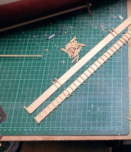
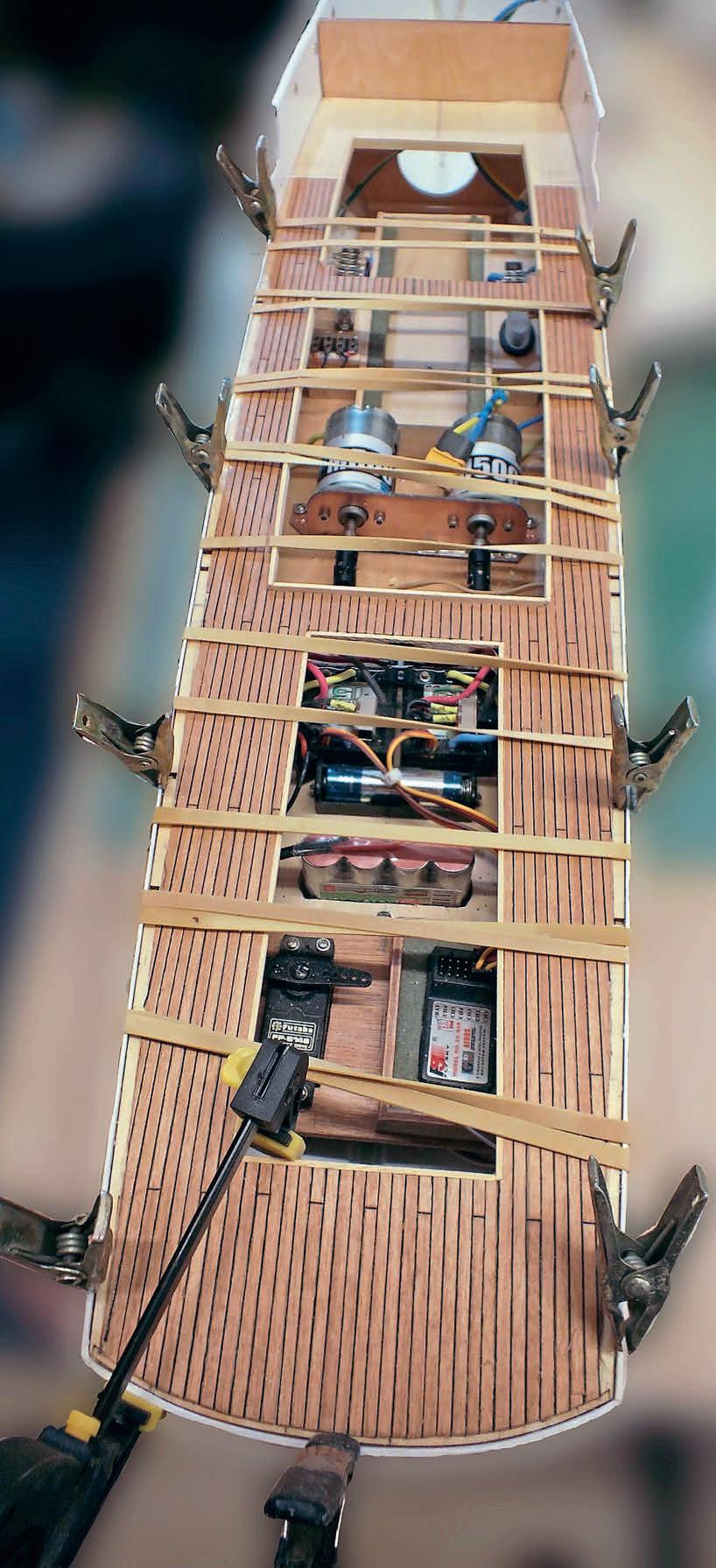
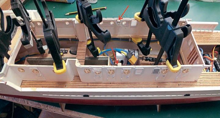
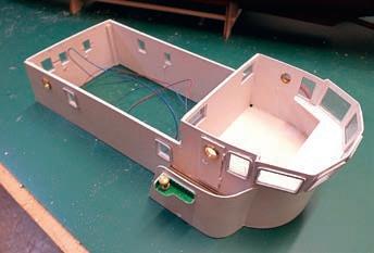
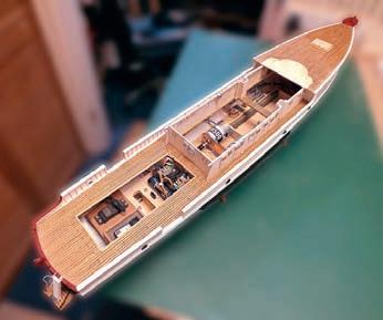
The bulwarks needed some detailed assembly and painting (see Photo 11) and a lot of tidying up was required before the completed cabin (see Photo 12) could be fitted. Magnets have always been my first choice for holding down a superstructure (note the holding magnets indicated in my photo by two red arrows). Photo 13 illustrates the completed forward deck, with the modified hatch and bulwarks (see Photo 13). Note, too, the thin 0.5 mm x 3mm plastic polystyrene strip on the edge of the auxiliary decks, which I feel gives a better edge and finish than just painting. I completed the upper cabin and wheelhouse shown partially finished in Photo 14 with the installation and wiring of the navigation lights. This required a considerable amount of care,
Flotation test
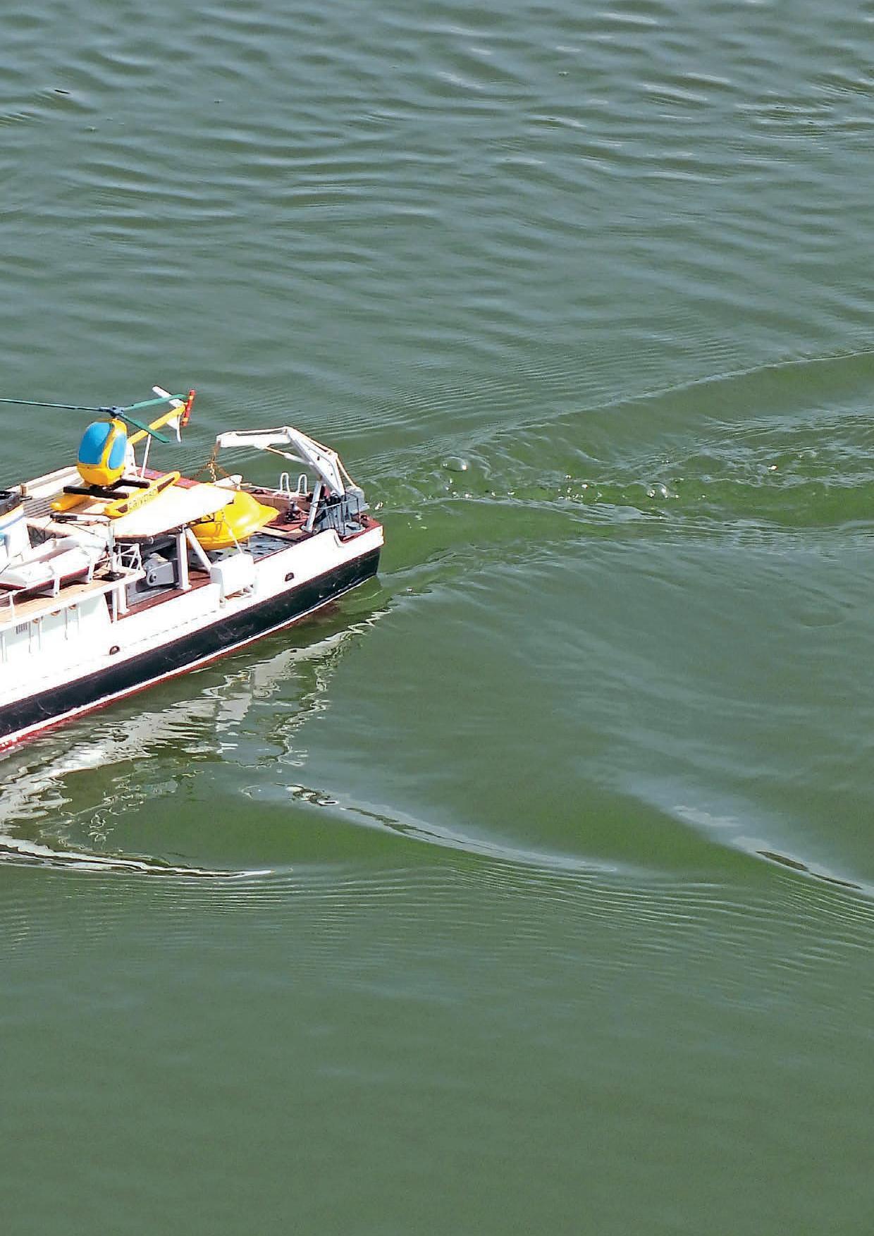
What I still needed to undertake at this point was a flotation check. I had expected, based on past experience, that I would need extra ballast, but was a little surprised by the result of my calculations. These suggested 1.2 kg would be required to stabilize and compensate for the extra top weight (courtesy of the brass fittings) and to ensure the model would sit correctly on its scale waterline. I therefore had to cut an aperture in between the motors in the baseboard so that I could lay the extra lead weight in the bottom of the hull. Fortunately, my estimation proved correct, as shown in the test sailing photos at the end of this article.
Superstructure assembly
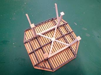
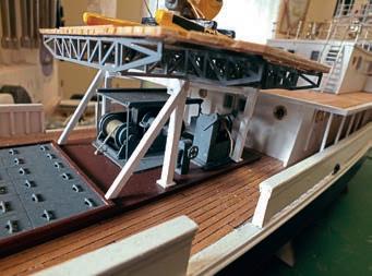
There are numerous sections (or what I call ‘mini kits’) to assemble for the superstructure, and I will show some of these here, although not necessary in the order in which they were constructed. Some of the items that detail the superstructure, such as the helicopter floats and the side tanks, are required to be built up of vacuum-formed components. Now, the truth is I’ve never been keen on vacuum-formed parts, as I find they rarely join together satisfactorily. I therefore discarded these in favour of carving my own interpretations in wood. In no way is this a criticism of the quality of Billing Boats’ kit, however, as I know there are many modellers out there who will be only too happy to work with the vacuum-formed items supplied and who will no doubt achieve far better results from them than I ever could.
I then jumped back to the main cabin to fit the removable upper deck supports, small link mounts glued and checked finished and
