







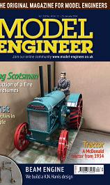
❖❖ Coventry WevisitRytonPools Cornwall NERAutocar Propane THEORIGINALMAGAZINEFORMODELENGINEERS Vol.232No.47388–21March2024 Joinouronlinecommunity www.model-engineer.co.uk Anew constructionalseries ArideontheBolton Abbeyrailway Anidealfuel
Published by Mortons Media Group Ltd, Media Centre, Morton Way, Horncastle, Lincs LN9 6JR
Tel: 01507 529589 Fax: 01507 371066
© 2023 Mortons Media ISSN 0026-7325
www model-engineer co uk
EDITORIAL
Editor: Martin R Evans
MEeditor@mortons co uk
Deputy editor: Diane Carney
Designer: Druck Media Pvt Ltd
Club News: Geoff Theasby
Illustrator: Grahame Chambers
Publisher: Steve O’Hara
CUSTOMER SERVICES
General Queries and Back Issues 01507 529529 Monday-Friday: 8 30am-5pm Answerphone 24hr
help@classicmagazines co uk
www classicmagazines co uk
ADVERTISING
Group advertising manager: Sue Keily
Advertising: Craig Amess
camess@mortons co uk Tel: 01507 529537
By post: Model Engineer advertising, Mortons Media Group, Media Centre, Morton Way, Horncastle, Lincs LN9 6JR
PUBLISHING
Sales and distribution manager: Carl Smith
Marketing manager: Charlotte Park
Commercial director: Nigel Hole
Publishing director: Dan Savage
SUBSCRIPTION
Full subscription rates (but see page 366 for offer): (12 months, 26 issues, inc post and packing) –UK £128 70 Export rates are also available, UK subscriptions are zero-rated for the purposes of Value Added Tax
Enquiries: subscriptions@mortons co uk
PRINT AND DISTRIBUTIONS
Printed by: William Gibbons & Son, 26 Planetary Road, Willenhall, West Midlands, WV13 3XB
Distribution by: Seymour Distribution Limited, 2 East Poultry Avenue, London EC1A 9PT
EDITORIAL CONTRIBUTION
Accepted photographs and articles will be paid for upon publication Items we cannot use will be returned if accompanied by a stamped addressed envelope and recorded delivery must clearly state so and enclose sufficient postage In common with practice on other periodicals, all material is sent or returned at the contributor’s own risk and neither Model Engineer, the editor, the staff nor Mortons Media Ltd can be held responsible for loss or damage, howsoever caused The opinions expressed in Model Engineer are not necessarily those of the editor or staff This periodical must not, without the written consent of the publishers first being given, be lent, sold, hired out or otherwise disposed of in a mutilated condition or in other unauthorised cover by way of trade or annexed to or as part of any publication or advertising, literary or pictorial manner whatsoever


http://www facebook com/modelengineersworkshop
http://twitter com/ modelengineers


Vol. 232 No. 4738 8 – 21 March 2024
368 SMOKE RINGS
News, views and comment on the world of model engineering
369 BUILDING 3020 CORNWALL IN 5 INCH GAUGE
Jim Clark builds a model of Francis Trevithick’s LNWR 2-2-2 locomotive
372 AN ENGINEER’S DAY OUT
Roger Backhouse takes a ride on the NER autocar at the Embsay and Bolton Abbey Steam Railway
377 PROPANE, AN IDEAL MODEL LOCOMOTIVE FUEL
Charles Reiter looks at the properties of propane that make it a good choice of fuel
381 GAS TURBINE ELECTRIC LOCOMOTIVE 18,100
Tim Coles reports on progress to complete a 5 inch gauge model of an experimental locomotive
384 WE VISIT THE COVENTRY MES
John Arrowsmith drops in to Ryton Pools in Coventry’s country park
388 1934 McDONALD TRACTOR
George Punter tackles another tractor construction project
391 A CENTRE FINDER FOR FOUR JAW CHUCKS
Dave Woolven presents a simple but useful accessory





392 BUTTERSIDE DOWN
Steve Goodbody returns with fur ther tales of the trials and tribulations of a model engineer’s life
394 THE PERPETUAL DEMISE OF THE MODEL ENGINEER
Luker argues that reports of the death of model engineering are greatly exaggerated
398 LNER B1 LOCOMOTIVE
Doug Hewson presents a true to scale fiveinch gauge model of Thompson’s B1
401 THE WILLIAMSON ENGINE REVISITED
Ray Griffin discovers a book by Tubal Cain from 1981 and builds the engine described in it
404 POSTBAG
Readers’ letters
405 THE AMERICAN LOCOMOTIVE
David Rollinson takes a look at the classic and ubiquitous 4-4-0 locomotive.
408 HERCULES – A TWIN CYLINDER COMPOUND ENGINE
Chris Walter describes a condensing marine engine first featured in Model Engineer 100 years ago
412 CLUB NEWS
Geoff Theasby compiles the latest from model engineering clubs around the world
415 CLUB
DIARY
Future Events
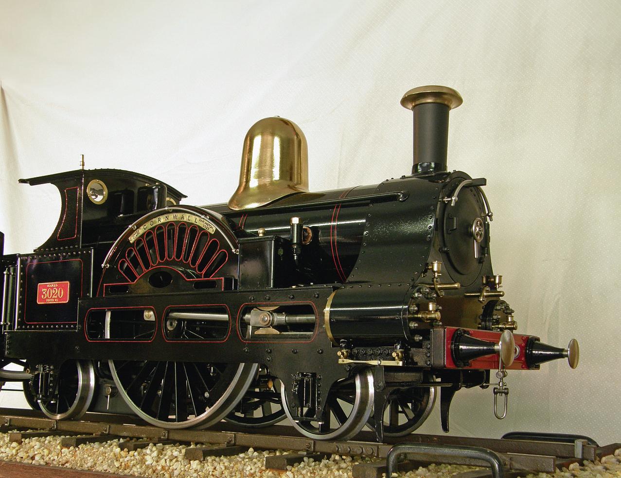
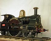
Jim Clark’s 5 inch gauge model of Francis Trevithick’s LNWR locomotive Cornwall as rebuilt by John Ramsbottom (photo Jim Clark)


www.model-engineer.co.uk 363
O N T H E C O V E R . . .
This issue was published on March 8, 2024. The next will be on sale on March 22, 2024 Coventry We visit Ryton Pools W R P Cornwall NER Autocar Propane THE OR G NAL MAGAZINE FOR MODEL ENGINEERS T E R N L AZI R DE ENG N ER 2 – 2 M h 0 Join ou o line c mmunity www mode -eng nee c k A new constructional ser es A ride on the Bolton Abbey railway An idea fue SUBSCRIBE & SAVE UP TO 49% See page 366 for details www.model-engineer.co.uk 388 405







Enjoy 12 months for just £68






Great reasons to subscribe
>> Free UK deliver y to your door or instant download to your digital device
>> S ave money on shop prices
>> Never miss an issue
>> Receive your issue before it goes on sale in the shop
SUBSCRIBE AND SAVE
P R I N T + D I G I TA L D I G I TA L O N LY P R I N T O N LY Q uar terly direc t debit for £19 1 year direc t debit for £68 1 year credit/debit c ard for £74 Q uar terly direc t debit for £22* 1 year direc t debit for £85* 1 year credit/debit c ard for £88* 1 year direc t debit for £50* 1 year credit/debit c ard for £54* *Any digital subscription package includes access to the online archive

classicmagazines.co.uk/ M E D P S 01507 529529 and quote MEDPS Lines are open from 8.30am-5pm weekdays GMT O ffe r e nds D e ce mb e r 31, 2024 Subscriptions will s t ar t w ith the ne x t availab le issue D ire c t D e bit p ay me nt s w ill continue on the agre e d p lan unless you te ll us othe r w ise To v iew the privac y p o lic y for MMG Ltd (pub lishe r of M o de l Engine e r), p lease v isit w w w. mor tons .co.uk /privac y Pl e ase v i s i t w w w.c l ass ic m ag a z i ne s .co.u k / te rm s for fu l l te rm s & con d i t ions . ( 8
Best of British


 MARTIN EVANS Editor
The UK’s premier nostalgia and heritage magazine, Best of British, celebrates classic entertainment, transport, food and drink, and the great British countryside.
DIANE CARNEY Assistant Editor
Regular features include Treasures in the Attic – a look at recently uncovered antiques and collectables, Postcard from which casts a spotlight on a British town or city to visit or stay in, and Window on the Past – a compilation of archive images and memories from The Francis Frith Collection As well as a lively six-page Postbag, readers are able share their stories in our Yesterday Remembered memoir section, while Doctor Who star Colin Baker writes about his personal connection to some the issue’s themes
Features in the March issue will include a celebration 60 years of Radio Caroline, a visit to Beaumanor Hall – Bletchley Park’s unknown other half, a chat with the Hovis boy, the history of the London Cigarette Card Company, a look at a British radio hoax that predates Orson Welles’ The War of the Worlds, and an interview with John Lloyd, the man behind Not the Nine O’clock News, Spitting Image, Blackadder and QI

Mar tin Evans can be contacted on the mobile number or email below and would be delighted to receive your contributions, in the form of items of correspondence, comment or ar ticles.
07710-192953
MEeditor@mortons.co.uk
Over the past 12 months we’ve looked at the origins of Slade’s Merry Xmas Everybody, gone on the trail of the real-life Dick Whittington, looked back on 100 years of the Shipping Forecast and 180 years of Nelson’s Column, uncovered the history of Bentley Cars, and celebrated 70 years of Quatermass, the golden age of motocross, and the recordbreaking InterCity 125.
We’ve also featured interviews with the stars of

Best of British
classic TV, film and music including Randall & Hopkirk (Deceased)’s Annette Andre, Blue Peter’s Sarah Greene, Last of the Summer Wine’s Sarah Thomas, Doctor Who’s Janet Fielding, The Bill/Carry On’s Larry Dann, Carry On’s Jacki Piper, Grange Hill/EastEnder’s Gary Hailes and Return of the Saint’s Ian Ogilvy
You can find out more on www classicmagazines co uk/ bob002
Bradford Cup
The Bradford Cup is to be awarded to the author of the best article or series, by popular vote, published in Model Engineer during the previous year. Last year’s winner was Steve Goodbody, for his series on The Eating of Elephants, who was presented with the cup at the National Railway Museum, York, by Adrian Shuttleworth, president of the Bradford Model Engineering Society
The organisers again invite nominations for the award of the trophy, to be submitted to the editor of Model Engineer by the end of March 2023, which should relate to articles published in Model Engineer during the year 2023 Readers will then be invited to vote for one of the top three nominations Submissions should include the following:
* The author’s name;
* The title of the article or series;
* The issue number in which it starts;
* Contact details for the person nominating the article
You may not, of course, nominate your own work!
Ellenroad Theft
I regret I have to report the theft of a couple of models Bob
Hayter writes to say:
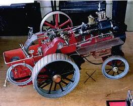
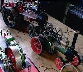
‘Our friends at Ellenroad Steam Museum, Milnrow near Rochdale, have unfortunately had a break in (late January) Stolen items were a collection of coins from the era when the mill was operating around 1900, a 1½ inch Allchin traction engine and a 1 inch Minnie. Neither model has a boiler number. Photographs are attached The museum can be contacted via their website www ellenroad org uk’ Please let us know if you see either of these
Scotsman Reverser
In Postbag last time (M E 4738, February 23) Mike Joseph asked why the full sized Flying Scotsman and Peter Seymour-Howells’s model had reverser stands of opposite handedness. Was this an error? As if happens, no, as some A3s were left-hand drive and some right-hand The full-size stand pictured is for a left-hand drive locomotive but the model, as drawn by Don Young, is righthand drive Phew! Whoever said model engineering lacked excitement?
Correction
We have a case of misidentification in Geoff Theasby’s article on the Bodo Air Museum (M.E.4738, Februay 23). Photograph 2 shows what is claimed to be a Westland Lynx helicopter Mr Phil Mortimer has written to me to point out that it is, in fact, a Bell 204 helicopter As a helicopter engineer who has worked on the Bell 204/205/212 series helicopters, he should know! To be fair, the outlines are fairly similar and I would be hard pushed to tell them apart
Model Engineer 8 March 2024
368
1½ inch Allchin
1 inch ‘Minnie’.
Ellenroad Museum
B U I L D I N G 3 0 2 0
in 5 Inch Gauge

Jim Clark builds the famous LNWR 2-2-2 – the
PA RT 1

The inspiration to build this locomotive
The idea of building this locomotive originated from discussions with a fellow member of the Northern Districts Model Engineering Society’s (Perth, Western Australia) Bill Walker in early 2017 Bill is very interested in the early history of railways and he showed me some postcards from his collection and an article in a book called Locomotives I have
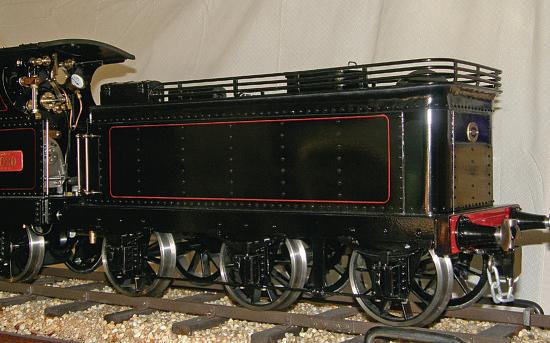
Known by J N Maskelyne, of a very attractive looking little locomotive, No 3020 Cornwall (photos 1, 2 and 3). He suggested I might like to try building a model of it I gave this some serious thought over a period of time and started doing some research on Cornwall A few things in its favour are that it still exists in preservation as part of the UK National Railway Museum collection and
there are some good photos of it available online; J N Maskelyne also provided some very detailed scale side and front elevation drawings of the locomotive and its tender in his book, based on his personal inspection
On the other hand, I could find no references to commercial model plans or castings being available, nor was there much information about any previous models of

369 www.model-engineer.co.uk >>
CORNWALL WAL
frst locomotive earmarked for preservation
The fnished model of locomotive 3020 Cornwall
A view of the Cornwall tender Lineside view of Cornwall 2
1
3
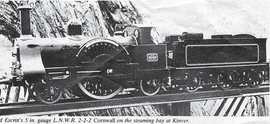
it that may have been made, apart from a picture of one in the UK in a 1982 Model Engineer magazine (photo 4)
If I was going to build Cornwall I would have to start from scratch and draw up my own plans for the model. Another challenge I thought I would like to take on was to fabricate everything, without using any castings The wheels in particular have very thin spokes and would be difficult to cast to scale anyway The biggest challenge with these was how to make the main driving wheels? My friend and co-conspirator in making difficult things happen, on Collins, came to the rescue here by suggesting that the spoke profiles could be wire cut out of a slice of steel billet.
So, with that encouragement, I set about drawing up the locomotive, scaling it for 5 inch gauge (the model to be approximately 1/11 of full size or 1 3/32 inch to the foot) I used J N Maskelyne’s outlines as the basis and scaled the other features off various photographs of the full-size
engine I decided it would not be an exact replica, but a coalfired operating model with an exterior that closely resembles Cornwall
To make it functional and hopefully reliable, I decided to use inside Stephenson’s valve gear similar to that fitted to the rebuilt Cornwall. However, I followed the valve gear design for another model locomotive previously published in Model Engineer magazine (August, 1976) by Martin Evans, with some modifications for my own layout I also made some further improvements after running the valve gear design through a software simulator for steam valve gear to check its performance in my application
I decided that the two horizontal outside cylinders would be simple fabrications with slide valves, the frames would be laser cut from steel sheet and there would be a standard Australian Miniature Boiler Safety Committee Codecompliant copper boiler The rest, as they say, is mere detail – but there is quite a lot of it!
Some history of the original locomotive
Cornwall has an interesting history which has allowed it to survive for over 175 years, although it had a major rebuild early in its life and has been overhauled several times since.
The locomotive was originally numbered No 173 and was built at the Crewe Works of the London and North Western Railway (L&NWR) in as a -2-2 configuration (photo 5) The designer was Francis Trevithick, the son of the famous Cornish mining engineer, ichard Tre ithick who was instrumental in the very early design and operation of high pressure steam locomotives for use in mines. Francis Trevithick was by this time the Locomotive Superintendent of the L&NWR The locomotive was named Cornwall after the county of his birth
Locomotive design during this era was highly competitive between the various railway companies and was largely focussed on the need for high speed for the emerging passenger services Each company was competing to offer the quickest possible journey times. The only way this could be achieved with the technology of the day was to have locomotives with extremely large driving wheels, so that the rotational speed could be kept low while the velocity along the track was high
Dynamic balancing of rotating and reciprocating
masses was poorly understood at the time and the strength of materials in use was variable Locomotives whose wheels rotated too fast would quickly og themsel es, and the track on which they ran, to pieces
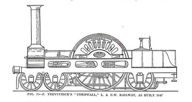
The main problem with using such a large central driving wheel was that its axle was high above ground and con icted with the boiler barrel, which needed to sit either above or below this axle Placing the boiler above the axle raised the whole centre of gravity and made the locomotive more unstable, not a property compatible with high-speed running
Thomas Crampton was another locomotive designer of the period who had come up with a solution to this problem, a few years earlier, by placing the large driving wheel at the rear, behind the firebo – a ery distinctive and quite elegant arrangement However, this necessitated a long, rigid wheelbase, which could damage the track Crampton designs were popular in France and Germany but not so much in England, although the L&NWR did have a few of them which may ha e in uenced the original design of Cornwall
Francis Trevithick’s answer to the speed and axle problem in the design of Cornwall was to use extremely large driving wheels (8 foot 6 inches or 2 6m diameter), placing the axle about 4 feet above the track, then slinging the boiler underneath it, with a transverse channel through the top of the boiler for the axle to pass through In order to keep the wheelbase reasonably short, the trailing wheel axle then had to pass through a water-jacketed tube through the inside of the firebo t worked, but all these complex compromises were difficult to manufacture, assemble and maintain
In 1857 John Ramsbottom became Locomotive Superintendent of the Northern Di ision (lines north of ugby) of the L W , based at Crewe Ramsbottom was another prolific and in uential figure
370 Model Engineer 8 March 2024
Bernard Escritt’s 5 inch gauge LNWR 2-2-2 Cornwall on the steaming bay at Kinver.
Photo credit: Model Engineer magazine
4 5
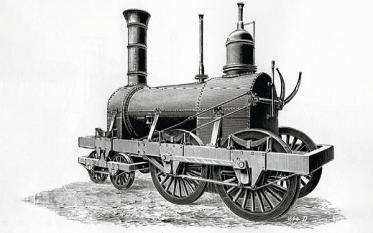
Cornwall as built in 1847 Photo credit: E L Ahrons (1927) British Steam Railway Locomotives Source: https://commons wikimedia org/wiki/ File:Locomotive Cornwall as built 1847 png
in steam engine development, his credits including the introduction of water troughs, the Ramsbottom safety valve and displacement lubricators, as well as other engineering inventions and improvements
In 1858, Ramsbottom redesigned Cornwall almost completely The young draughtsman who did the detail design drawings was to become yet another in uential figure in railway history –Francis Webb
Little of the original Cornwall survived the rebuild unchanged, other than the outside frames,
the connecting rods, the driving wheels with their distinctive ‘paddle wheel’ style splashers and, of course, the name. The wheel arrangement was now 2-2-2, shortening the wheelbase to just over 14 feet
A new boiler was placed entirely abo e the centre driving axle in what would now be regarded as conventional practice, with the firebo dropping down between the centre axle and the trailing wheel axle New cylinders were provided, fractionally smaller at 17¼ × 24 inches, with Stephenson’s valve gear
inside the frames Standard L W fittings replaced the original Crampton-like features, including Ramsbottom’s newly designed tamper-proof safety valves
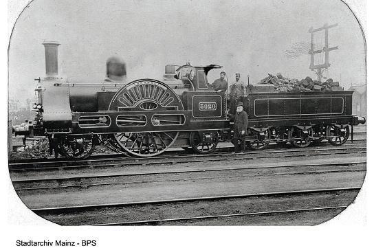
Another minor re-build in the 1870s provided a typical L&NWR style cab, with a short roof and semi-open sides. Cornwall was renumbered No 3020 in 1886, as shown in photo 6
Cornwall was a very successful, high-speed passenger express locomotive of its period Records exist showing it running at an average speed of 50 7mph between Crewe and Chester in 1884, reaching top speeds over 70mph It has been claimed that the locomotive achieved a speed of 85-90mph in 1919 and legends persist that it once topped the magical 100mph This seems unlikely given the technology of the locomotive and the state of the track at that time, but it certainly had an exciting turn of speed!
The engine in its present condition dates from 1887 when it was given a new boiler and a circular smokebox door Cornwall remained in regular passenger service

until December 1907 when it was withdrawn and put into Crewe Works Museum for a short time In 1911 it returned to service until 1913, at which time it was fitted with a combined tender and saloon on a six-wheeled underframe and put into service as the Chief Mechanical Engineer Charles Bowen-Cooke’s personal inspection train
It appears the CME had a particular affection for Cornwall. The locomotive’s normal black dome casing was rubbed back to polished brass, which was almost certainly unique on an L&NWR engine, and which it reputedly retained until 1927 It is last known to have operated in service in July 1920 when it conveyed Charles Bowen-Cooke in the CME saloon to Euston to visit his doctor. On its final retirement, Cornwall was deliberately put aside for long-term preser ation, one of the first locomotives to be treated this way By this time it had covered more than 1,000,000 miles in service
Cornwall took part in steam during the Stockton & Darlington Railway and the Liverpool & Manchester Railway Centenary celebrations in 1925 and 1930 respectively Cornwall retained its authentic L&NWR livery until early 1949, when it was repainted at Crewe It was then exhibited at the Museum of British Transport at Clapham between 1963 and 1973 It returned to Crewe Works in 1975 prior to being acquired by the National Railway Museum and going on display at the NRM in York
Cornwall was scheduled to take part in steam at the Rocket 150 celebrations at Rainhill in 1980 but the state of its boiler was found to be far beyond economic repair It has since been cosmetically restored and has been out on loan for display at various venues (photo 7) Unfortunately, it appears that this graceful old survivor Cornwall is unlikely to ever run in steam again but perhaps the model will!
371 C O R N W A L L www.model-engineer.co.uk
To be continued
Cornwall at Shildon in 2009 Photo credit: Gillett’s Crossing from Bristol, United Kingdom
6 7
Cornwall as rebuilt in 1858 Photo credit: Unknown, public domain Source: https:// commons wikimedia org/wiki/File:HLB Lok 2 jpg
An Engineer’ s Day Out A r i d e o n t h e N o r t h E a s t e r n R a i l w a y A u t o c a r

Roger Backhouse spends the day at the Embsay and Bolton Abbey Railway
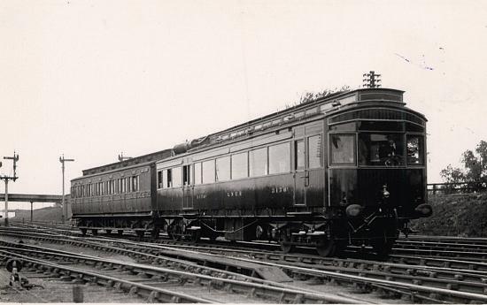
In September last year I enjoyed a very pleasant day out with York Model Engineers - for a train ride (photo 1). Not your average preserved railway trip but to tra el in the world’s first internal combustion passenger train (photo 2) It is arguably just as significant in railway history as Stephenson’s Locomotion or Rocket as it pioneered today’s diesel electrics and multiple units Over lunch members also enjoyed a presentation about the restoration by Stephen Middleton and Steve Hoather, both long term volunteers in the NER Electric Autocar project Theirs was a remarkable story.
The railway
After years of dereliction, the autocar has been superbly restored and now runs regular services on the Embsay and Bolton Abbey Steam Railway, one of Yorkshire’s shorter preserved lines at 4½ miles, but with plenty to see The line is part of the former Midland Railway route from Skipton to Ilkley, where it linked to the North Eastern Railway The preserved line keeps much of the Midland a our with a Company signal box at Bolton Abbey, originally from Guiseley (photo 3) If the station seems large for the area, remember this line once handled significant e cursion
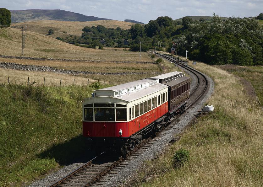
traffic from Yorkshire’s cities to this attractive area which is close to the present Yorkshire Dales National Park
The autocar
At the start of the 2 th Century, the North Eastern Railway was a highly enterprising company Wilson Worsdell was Chief Mechanical Engineer and Vincent a en Assistant CM
In the face of competition from electric tramways which were hitting urban passenger serices, it electrified lines around Tyneside with great success It had plans for mainline electrification from York to Newcastle but these were aborted by the First World War and later amalgamation into the London and North-Eastern Railway Engineers knew of the success of electric motors driving trains and were interested in possibilities on branch lines where the expense of third rail or overhead electrification could not be ustified Their solution was to create railcars which had a petrol engine that drove a dynamo to power the electric motor. Diesels were not then developed for transport use. These were the world’s first internal combustion powered electric driven rail vehicles and anticipated later diesel multiple units There was no need for a locomotive to run round a train and operation would be cleaner for passengers (photo 4)
Experimental railcars, numbered 3170 and 3171, were built at York Carriage Works in 2-3, the first
372 Model Engineer 8 March 2024
1
The NER Autocar with trailer on the Bolton Abbey and Embsay Railway Photo: Ian Cawthorne, 2023

entering service in 1903.
Although looking much like electric railway carriages of the period, with a clerestory, bow ends and large windows, they housed an engine room and had upholstered tramway type reversible seating (photo 5)
Like other carriages of their period they were made of wood and matchboard sides gave a decidedly American look They had an open saloon, an engine room with the driver’s position, a vestibule and then a rear driving compartment so the car could be driven from either end.
Inside they had electric lighting and had a certain ‘Pullman’ touch with the addition of curtains at the windows and so were popular with passengers Both autocars had a whistle fitted, blown via an electrically driven compressor Besides airbrakes there was an electric track brake as in tramway practice
After first installing a ertical Napier engine, which was not
successful, the NER tried an 80 hp Wolseley petrol engine which was effective and lasted in service until 1923 when 3170’s engine was replaced with one of 225 hp, reputed to have come from a First World War tank (photo 6) This enhanced the torque and allowed it to haul an autocoach trailer Though maximum speed remained at around 36 mph the autocars were still considered underpowered
It’s worth remembering that this was a real pioneering enture the world’s first use of an internal combustion engine in a passenger carrying rail vehicle
First used from Hartlepool to West Hartlepool, the autocars later operated routes including Scarborough to Filey before working the Selby to Cawood branch From 23 3170 worked services around Starbeck and it may have supplemented services on other LNER lines Rapid starting

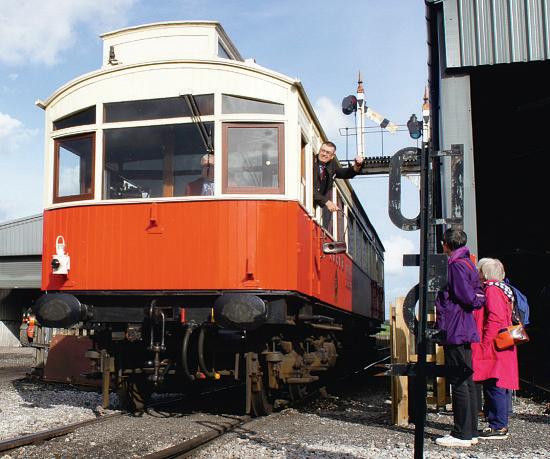
would have made autocars ideal as a complementary service
There is no evidence of a trailer except in one old photograph which may have been taken after the Autocar was re-engined in 1923 The NER Autocar Trust has added a trailer to increase carrying capacity
Despite rapid acceleration the railcars had a limited top speed, though that could have been improved with a more powerful engine Given the services operated, high speed was not a priority
In retrospect it seems surprising that the railcar concept was not developed by the LNER Perhaps internal combustion railcars did not fit with a steam dominated LNER mindset which used Sentinel

Advertisement for a Wolseley engine These were the second engines to be installed and lasted until 1923
steam railcars in the 1930s It was a missed opportunity for the railway
373 A U T O C A R www.model-engineer.co.uk >>
Frontal view as the Autocar arrives at Embsay watched by members of York Model Engineers.
York model engineers await departure of the North Eastern Autocar They thoroughly enjoyed their ride
NER Autocar no 3170 with trailer photographed near Poppleton Junction probably around 1923 Photo: Ken Hoole Study Centre
6
Signal box from Guiseley helps keep the Midland spirit of the line evident
2 4 5 3

Dereliction and restoration
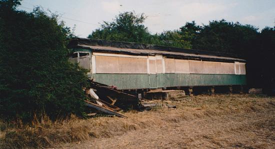
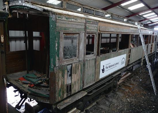
The autocars were withdrawn in 1930 and 1931 One was scrapped but the body of 3170 was sold and mo ed to a field near Kirbymoorside as a holiday home (photo 7) Stephen Middleton, a self-confessed Victorian carriage enthusiast, says ‘it was disguised as a hedge’ and arranged for its removal He found original interior wood in surprisingly good condition but no underframe Stephen then formed the NER Autocar Trust, a registered charity. They approached the Heritage Lottery Fund (HLF) for financial help who allowed two years for the Trust to prepare a business case before agreeing funding After a commercial firm asked for 2 , ust to prepare an estimate of work needed, Steve Hoather, a retired British Rail engineer involved in the introduction of HSTs to service on the East Coast Main Line, wrote the performance specification Details
were agreed with trustees and they approached fi e firms for quotes to do the work.
Key points included the need to operate as a two car unit, as carrying more passengers improved operational economics t specified a maximum speed of 25 mph, as found on preserved railways, and an ability to start on a 1 in 49 gradient, the steepest on a British preserved line, as the Autocar might move to different railways An underframe, engine and a motor bogie were required
After using a temporary underframe, the Trust sourced a near correct frame, with Fox bogies and turnbuckle truss rods, from the North Norfolk Railway where it was used as a crane runner They found former Southern Region motor bogies in Buckinghamshire, formerly fitted to a andite de-icing unit The trailing bogie was restored at the Ffestiniog Railway’s Boston Lodge works
As the original engine had
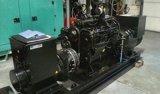
long gone and petrol engines are no longer permitted, the engine (photo 8) was a new Cummins L si cylinder litre diesel It runs at 1800 rpm and powers main and auxiliary three phase alternators The main alternator operates two standard outhern electric DC EE507 traction motors through a rectifier obtained from a Class locomoti e fitted for electric train heating (photo 9)
With these key elements available, the Heritage Lottery Fund recognised the importance of the project and agreed to fund the full amount re uested of , . The Trust had previously sought bids to carry out the work and Brush at Loughborough agreed to quote for restoration, but when Wabtec took over Brush they wouldn’t do the work However, it was carried out under the direct supervision of David Moore and coordinated by Steve Hoather The HLF asked that the work be completed in fi e years
and eventually it took seven (photo 10)
Steve Hoather describes himself as a ‘Steptoe’ looking round for scrap parts, receiving ‘excellent cooperation’ from all around the rail industry Even engineers he’d never met were amazingly helpful Brakes are a British Rail type automatic air brake, in line with NER practice which used Westinghouse braking There are separate brake cylinders for each bogie Brake valves came from Northern Ireland Railways and West Coast Main Line stock The original vehicle was air braked, then, around 1930, the LNER converted it to vacuum brake and it is now dual air/ vacuum braked
The controller and deadman’s pedal were from a Class diesel, cab gauges from an HST unit, the controller handles from a Class shunter and a rectifier from a Class diesel t is uite a Heinz vehicle!
The whistle may bring
374 Model Engineer 8 March 2024
erelict autocar in a feld near Kirbymoorside nside the condition was surprisingly good Photo: Stephen Middleton, 2003
Underframe with Cummins engine under test on the Great Central Railway
Photo: Alan Chandler, 2016
The Cummins diesel engine was chosen and installed Photo David Moore, 2012
7 9 8 10
Body work restoration Photo: Alan Chandler, 2015
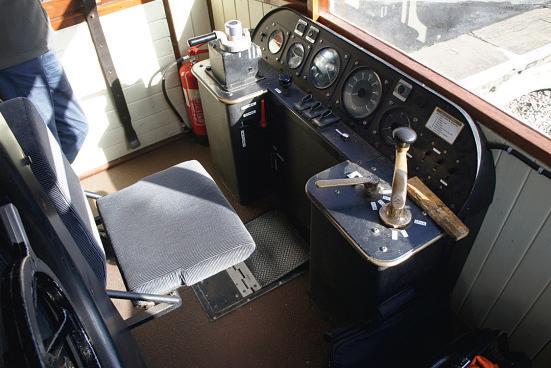
back memories for London commuters Familiar to those who’ve used London’s Metropolitan line, it came from LUL Amersham rolling stock Cab controls are similar to most British Rail locomotives with a standard controller
desks (
11) pdating included fitting fire detectors and the engine is in a specially made housing offering a minimum of thirty minutes protection which allows time for evacuation


should that be necessary. HLF re uires educational benefits to be apparent so an array of dials and gauges shows exactly what’s happening with the engine nterior fittings include upholstered reversible seats copied from those on a Grimsby and Immingham tram at Crich (photo 12) Curtains ha e been fitted to the power car, which is electrically heated, and there are e en straps fitted for standing passengers. The electric heating fitted has to cope with a variable voltage/ variable frequency supply from the alternator Drawings and a spares list have been prepared for future reference
The trailer
The NER Autocar Trust has added a trailer to increase carrying capacity This came from the Coach Association based on the North York
Moors Railway, who donated NER autocoach No 3453, built in 1904 They had restored it cosmetically in 1975 but since then it had deteriorated significantly
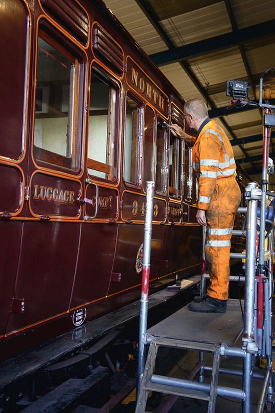
The autocoach was an historically appropriate matching vehicle to use as a trailer having the round porthole windows in the van end shown on the old photograph mentioned above It was originally a steam pushpull driving coach. This vehicle too has been superbly restored. During York Model Engineers’ visit, Trust volunteer, John Furness was varnishing the woodwork (photo 13) He was responsible for all the painting, varnishing and lettering on the Autocar sides and what a beautiful sight it is (photo 14) uite incredibly, the orth Eastern Railway transfers are original, reportedly found in a drawer at York Carriage Works
375 A U T O C A R www.model-engineer.co.uk >>
key David Moore built the cab
photo
View of the driving position Control arrangement is similar to British Rail era diesel locomotives
NER Autocar Trust volunteer, John Furness has done all the painting, varnishing and lettering and is seen here varnishing the trailer.
Autocar interior superbly restored with reversible seats and electric lighting Photo: Alan Chandler, 2017
11 13 12 14
Autocar lettering is superb.

After the ride
Following their ride on the Autocar, York’s members enjoyed a conducted tour of the railway sheds where a number of interesting carriages, including several classic vehicles belonging to Stephen Middleton’s Stately Trains were seen Some are available for hire on special trains
One special ehicle is ueen Victoria’s saloon, built for her travel by the London and South Western Railway (photo 15) The realistic dummy of the ueen was found in a skip, thrown out by the National Railway Museum Her Majesty was not amused.
Other vehicles seen were an LNER Thompson buffet car that probably featured in the film Elizabethan Express, a Bulleid carriage and a London and North Western Railway Director’s saloon Two LMS built coaches from Ireland had been sent there following an air raid on Belfast that destroyed much stock Having been re-
gauged to 5 foot 3 inch, they are now back on UK standard gauge bogies
Locomotives included a Fowler diesel shunter and a Lancashire and Yorkshire Railway 0-6-0 outside (photo 16)
Operation
The Autocar has operated on the Bolton Abbey to Embsay Railway since 2019 Beside summer service trains, usually on Mondays, the Trust also offers driver experience days
Thanks to an Cawthorne, Alan Chandler, te e oather and Stephen Middleton for help with this article and use of photographs. Particular thanks to Dianne Clunas who organised the visit (photo 17) A donation will be made to the NER Autocar Trust
Thanks also to staff and volunteers at the Embsay and Bolton Abbey Railway for their help in making this a great day out


Further information:
The NER 1903 Autocar Trust Membership Secretary
2 Lairs Crescent, Snainton, North Yorkshire YO13 9BQ
Website: www.electric autocar.co.uk
Embsay and Bolton Abbey Railway
Bolton Abbey Station
Bolton Abbey, Skipton, North Yorkshire BD23 6AF
Phone: 01756 710 614
Talking Timetables & Fax: 01756 795189
www embsayboltonabbeyrailway org uk
Note that the Autocar may be hired out to other railways but details are not yet confrmed
Group visits
York Model Engineers enjoyed their day out. Why not organise a visit from your model engineering society? You won’t be disappointed.
Reaching the railway
There is a large car park at Embsay Station The Dalesbus minibus service runs hourly on Mondays to Fridays from Skipton to Embsay and there is an infrequent Sunday service from Skipton railway station
Note – the railcar is as at the GCR in Loughborough for the winter ME
376 Model Engineer 8 March 2024
The London and South Western Railway built this saloon coach for Queen Victoria
Busman’s holiday? Dianne Clunas was a driver with TransPennine Express and organised York Model Engineers’ visit Seen here trying out the Autocar controls
15 16 17
Lancashire and Yorkshire Railway 0-6-0
Pr o p a n e , a n I d e a l M o d e l
Locomotive Fuel L ti

Charles Reiter explains the enefts of sin propane to fre miniat re locomotives
Propane gas ( g 1) is not manufactured, it is a fossil fuel separated from crude oil by a process called ‘cracking’, discovered in 1857 by the French chemist Marcellin Berthelot and again in 1910 when it was discovered by American chemist Walter Snelling as a component of the then gasoline. He had the good sense to patent it. Gasoline was at that time sold in gallon sized containers and was very volatile Buyers complained that they would get a container and by the time they tried to use it about half of it would ha e ashed off into the atmosphere The higher vapour pressure of the propane component would boil off and cause the gasoline to be agitated and vapourize too Propane and butane are very alike and can be used in the same burner systems except that propane has a much higher vapour pressure At 70 degrees Fahrenheit propane’s
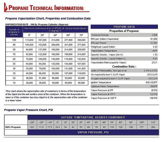
vapour pressure is 110 psi, versus 35 psi for butane This is why your BBQ tank is steel and your pocket lighter is made of plastic Oddly, butane has a slight edge in the amount of heat per volume In the southern United States the propane you buy has more butane in it especially as a ‘summer’ mix and if you get your motorhome tanks filled while on summer vacation in Texas you won’t be able to get a ame in Minnesota at Christmas Propane and butane are both heavier than air and so they will ‘pool’ in containments like boats or closed bottom rail cars This is compounded by the fact that compressed gasses leak unnoticed through very tiny openings With pressures of 100 psi and above propane systems have to be durable Pipes and hoses should be rated for pressure. Propane hose is rated for 300 psi and is physically durable
For our use the propane pressure needs to be reduced This is accomplished by mounting a regulator at the tank I recommend barbecue regulators that are adjustable and also recommend a gauge in the line so you know what your pressure is Barbecues usually run at about 3 pounds pressure and most of the locomotive burners I have seen operate at 5 to 10 pounds of pressure.
A propane fire is basically just hot gas Sure, there is some radiant energy released but nothing like our traditional solid fuels The biggest problems for the use of propane in model locomotives are poor burner design and a lack of understanding of just what is happening in the firebo o many burners
are mounted too high The refitting of a gas burner to a coal burning locomotive is generally with the manifold mounted near the level of the original grate, with barber jets These place the ames almost two inches higher than the grate so much of the water legs is heated by conduction, not directly Add to that the cold air owing into the firebo and cooling the firebo wall. I suppose you could make a case for ‘it’s preheating the air’ but warmer air is less dense I read a study of model locomotives that claimed that of the heat of a coal fire was transferred in the firebo You can imagine that it’s going to be a lot more evenly distributed with a gas fire
All of the ‘science’ of smokebox draughting and petticoats is pretty useless for propane The ideal draughting now is to eliminate the pulsations of the exhaust up the stack and create a low but constant draught The draught should draw secondary air into the firebo and e acuate the burnt fuel into the smokebox at a rate that just matches the gas burning rate That’s the ideal because with too little draught your fire becomes too rich and stinky as partially burnt gasses choke the fire Too much draught and you’re just wasting energy as the heat that is produced is very quickly evacuated to the smokebox and blown up the stack.
The secondary air is the air that is drawn into the burner area around the ames to provide an abundance of oxygen to further complete combustion Air of course is a mixture of gasses and the one we need is oxygen which is typically 21% of the air The
377 www.model-engineer.co.uk >>
Some data showing the relative temperature pressure relationship and storage capacities
Fig 1

other gasses are along for the ride and are a medium to carry the heat So the superheated gasses want to dump that heat and at 1500 degrees or so, a 300 degree locomotive boiler looks really cool The challenge is to get enough gas to transfer its heat to the boiler walls, without pulling in too much cooling gas
Primary air is that air that is initially mixed with propane gas in the burner to allow the gas to burn well, combining the hydrocarbons with oxygen It is a reaction that starts with the addition of a little energy (a spark) and then the reaction releases so much heat it is easily self-sustaining The burners job is to mix those gasses in the right ratios to release the maximum amount of heat The volumes of propane to air are very different Remember there is a lot of gas (78%) that is not part of the reaction that also needs to pass through the burner


Hence the great size difference between the gas orifice and the ports supplying the air Also, just to complicate this already complex system, we mix pressurized propane with air at atmospheric pressure
A jet of propane shoots out of the orifice at high speed expanding as it goes and the slight vacuum created behind it, drags the air into the burner Ideally, there is enough but not so much air that you diminish the slight vacuum pressure in the mixing area
Of course, we desire a system that has a wide control area and we control the output of the burner by turning up and down the gas ow Let me point out that every valve is a pressure regulator, and as we close the control valve the gas pressure at the orifice (mixing jet) is lowered and the
gas jet is not as energetic so the vacuum pressure drops and the amount of air dragged into the mix decreases But it is not linear The good news is that the system is fairly tolerant of these changes and our use
is fairly constant I mean you use about the same amount of heat constantly unless you are just not using any steam If your burner was too big then you could find yourself using less heat and operating in an inefficient area where the gas mix will go rich from not inducing enough air
It seems like an ideal system would be one that turns on the required number of burners as needed I built a burner array like that but although the theory was good, burners that are just sitting in the firebo with no cooling gasses owing through them melt Furthermore, in testing, throttling the gas supply worked as well as the staged burners.
The burners
Li e steamers basically use three types of burners - Barber jets, impinged burners and bar burners, and that seems to be

378 Model Engineer 8 March 2024
1 2
5
3 4
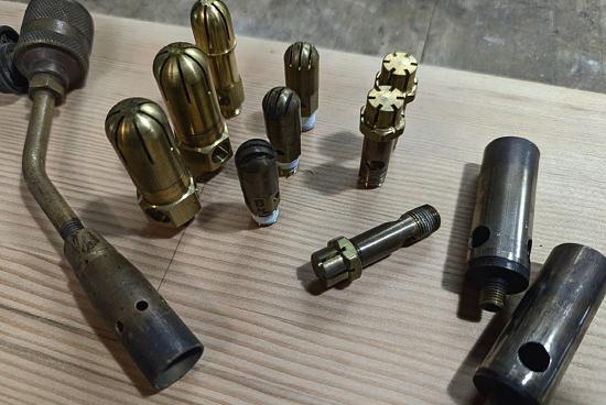
A group of Barber jets, star and fan pattern With a couple of jet burners and a propane torch head as well
A home-made eight jet impinged burner with temporary gas connection for test
This burner was later replaced with one that was even thinner The tube to the left is a venturi mixing the gas and air
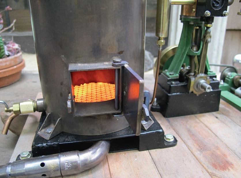
A really extravagant and a simple bar burner. A ten-jet impinged burner with extra, smaller jets that create less heat. Also, a ceramic burner tile and mixing venturis both home-made and salvaged.
Not quite, full burner

in order of popularity (photo 1)
Barber jets are a family of individually mixing units with various sizes and top caps to spread the air/gas mixing different patterns. The most commonly used is the star pattern By making a manifold with mounting holes, arrays of burners can be created very easily and with some care the results are very successful The burners need to have enough room around them for the ame pattern to do its ob of mixing in the secondary air For narrow firebo es a fan pattern can be a better choice and with the fans spreading across
the width more burners can be utilized
I recently built a burner with a single row of six fan burners ow it’s fi e burners because the air coming into the burner caused the furthest burner to starve and not mix gasses well The burner assembly worked better with fewer burners operating at higher levels Larger fire bo es can benefit from an impinged burner design (photo ) An impinged burner utilizes pairs of burner jets that have no spreader caps The air/fuel mix is a stream and the pair of burners is mounted to cause the gas
streams to impinge on each other at 90 degrees In use a ball of ame is formed at the point the streams impinge and this ball of ame uses all the air it needs This type of burner is ery efficient and clean burning and it also seems to throttle well - a time when ‘crossing the streams’ is a good thing. The mounting for the jets is more complicated but burner units made of cast iron are easily available through the internet The obvious issue is that this type of burner needs a bit more height in the firebo
I recently supplied a friend with a larger impinged burner for a gorgeous antique coal stove that heats his home and we ended up plugging four of the jets to lower the amount of heat It was already using the smaller type of jet burner but this fine tuning made it ust what he needed (photo 3).
Bar burners are often seen in stove ovens and barbeques (photo 4) The style is a piece of tubing with many narrow slits cut into the top surface or rows of perforations In its simplest form the gas/fuel mix is accomplished at one end with a et of gas firing through a simple venturi to drag the air
in and mix with the gas This mi ture then ows through the slots or perforations The gas pressure in the tube is ery low but the ames cannot propagate through the little holes
Another burner I need to mention is one of my own devising. It was inspired by the need to have a good burner in the very shallow space under a tee boilered hay, specifically a model of the MichCal #2
Based on the Bill Harris design, there is very little space under the boiler To mount Barber ets in the firebo would place the burners very high and the air inlets to the burners would be in the area of the fire arris used a modified ersion of the Shattock pot burner for liquid fuel vapourization
I built a burner plenum by making a box with circular arrays of burner holes, each around a center tube that passed down through the plenum to bring a source of secondary air into the circles of ames The plenum is then fed by a venturi gas mixing system similar to the bar burner (photo ) Essentially, I just changed the format of the bar burner to fit the space t works quite well and gets the ames right to the bottom of the firebo t can be built as a replacement for the ashpan structure. Beyond the Shay I have equipped a ‘Speedy’ (British design) with it, a vertical boiler unit, and another locomotive with a small firebo All e hibited e cellent results When driven very hard the indi idual ames on the gas holes cease and the area becomes a mass of burning gas
There are other types of propane gas burners, radiant types, ceramic and stainless and jet burners but they have not proven to be successful in our general size category. Ceramics are often used in G scale sizes and would be a possibility for 2 or 3½ inch gauge locomotives (photo 6) Jets burners are fine but noisy (photo ) I over burnered a Falk 1 locomotive with four jets
379 P R O P A N E www.model engineer.co.uk >>
6
7
Here’s a ceramic burner in a 4 inch diameter vertical boiler using a propane torch burner as a mixing system
ere is a two- et burner for a Tich frebo t is made with repurposed propane torch burners

And have to show this - Ken Brunskill was dissatisfed with the arty burners he made and so he devised another top cap ’ve named it the Brunsen Burner’ and it works really well t took a lot of e perimentation but it gives a really good ame pattern
Installation
The parameters of burner installation are driven by many factors First off, we need to remember that everything will get hot Sounds simple but it is often overlooked and I have seen rubber hose connected to a fitting on the burner pipe A length of copper line does not isolate the heat much so be sure your controlling valve is up to the requirements Another often forgotten item is the need to remove the burner for boiler inspection, so the burner assembly should be removable with a couple of screws or pins That, and an easy gas line connection will reward
your forethought over and over
The burner needs good access to the air so if anything, open screening is about all you can put across the bottom I have seen even 50% screens being too restricting and the burner running rich.
The sort of burner you use is affected by physical requirements As always, the best approach is to see if there is a similar locomotive that is running successfully and evaluate how that would fit to your application ere is where you have the opportunity to improve on what has been done
Let’s also address safety
The output of burnt gas is carbon dioxide (CO2) and carbon monoxide (CO) for the most part so only test and operate in a well-ventilated area Also stay aware of the fact that it’s an ignition source so be care with volatiles.
Making burners
Yes if you’re handy in the shop and willing to take on a repetitive task, burners can be successfully built And they can be modified as well There are designs for Barber jets available and they have been around so long that there are no patent restrictions I have built all sorts of burners but lately so


many are available that time is better spent on other areas, as long as these burners suit your needs (photo )
Here is an article written by GGL member Da e August on his very successful method of making Barber jets (aka: Marty burners) note the six burners for his L American www.discoverlivesteam.com/ magazineold/186/index htm
I suppose the overall point of this article, beyond information, is that more is not always more and care in design and experimentation should be embraced This coupled with educated operation will give you the reliable and easy steaming you desire
So why did I say that propane is an ideal model locomotive fuel?
Simply, you can turn it off with the twist of a knob - heat with an off switch.
For further reading solar o com/products/ This is probably the largest supplier of engineered burners If you want to buy 500 Barber jets or heat full size railroad cars they are the people to talk to
380 odel Engineer 8 March 2024
E
Barber jets
8
Solar o.


 MARTIN EVANS Editor


