4 minute read
Finishing Ellie, t e team ram
This is a follow up article on building my version of Ellie, the Steam Tram The first part of two instalments of the original article being published in Model Engineer on 28 January 2022 This article continues the description of the construction of the model to its first steaming and the modifications made to improve performance and ease of use
The first article described the designing and making of a single cylinder, double acting steam engine that was fitted with a reversing system to replace the single cylinder, single acting engine with no reverse of the original version as described by Andrew Allison in his book, Ellie the Steam Tram.
The article ended with the model consisting of a chassis with a finished engine, a gear and chain drive to the wheels, a part-built boiler fitted with heat exchanging rods and a completed ceramic gas burner.
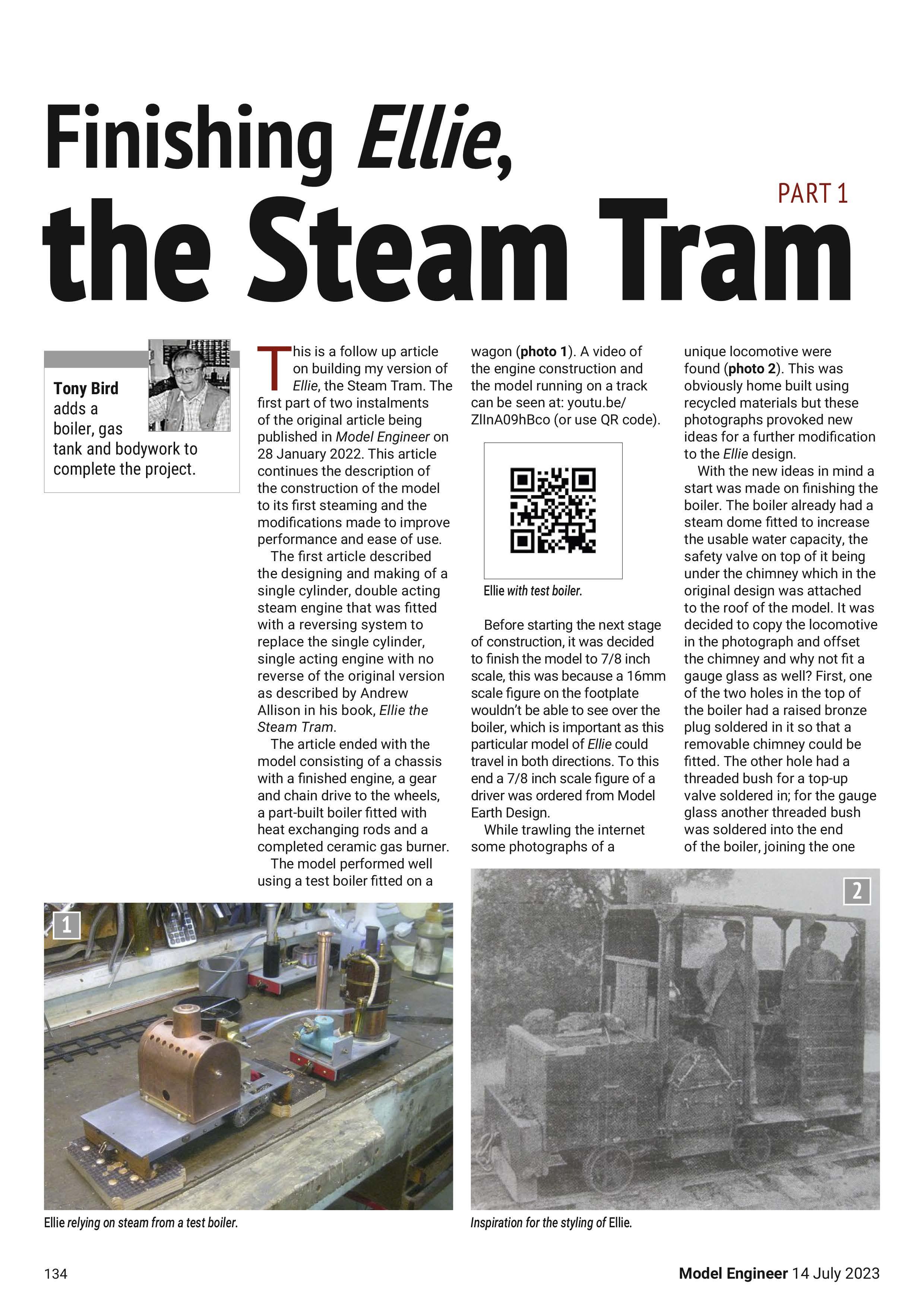
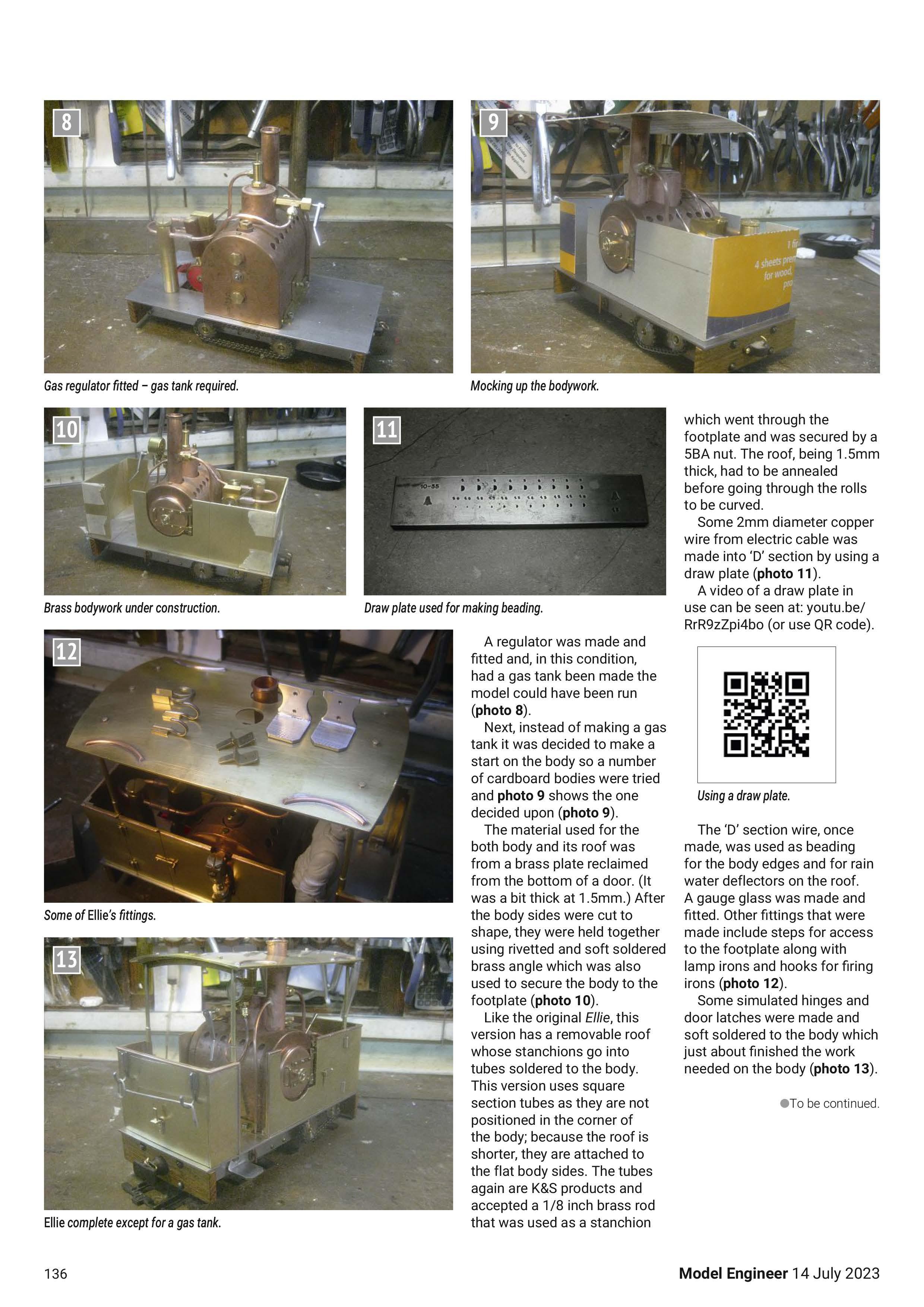
The model performed well using a test boiler fitted on a wagon (photo 1) . A video of the engine construction and the model running on a track can be seen at: youtu be/ ZllnA09hBco (or use QR code) unique locomotive were found (photo 2) . This was obviously home built using recycled materials but these photographs provoked new ideas for a further modification to the Ellie design
Before starting the next stage of construction, it was decided to finish the model to 7/8 inch scale, this was because a 16mm scale figure on the footplate wouldn't be able to see over the boiler, which is important as this particular model of Ellie could travel in both directions To this end a 7/8 inch scale figure of a driver was ordered from Model Earth Design
While trawling the internet some photographs of a
With the new ideas in mind a start was made on finishing the boiler. The boiler already had a steam dome fitted to increase the usable water capacity, the safety valve on top of it being under the chimney which in the original design was attached to the roof of the model. It was decided to copy the locomotive in the photograph and offset the chimney and why not flt a gauge glass as well? First, one of the two holes in the top of the boiler had a raised bronze plug soldered in it so that a removable chimney could be fitted The other hole had a threaded bush for a top-up valve soldered in; for the gauge glass another threaded bush was soldered into the end of the boiler, joining the one
Displacement lubricator fitted to Ellie . already there that would have been used for filling the boiler. With all the bushes soldered in place the holes in the boiler were plugged and the boiler tested for 10 minutes at 100 psi for a maximum working pressure for the boiler of 50 psi (photo 3)

A swivel cover was fitted over the hole in the boiler flame guard that would be used to light the burner. The chimney was made from a 15mm copper pipe and would be used to remove oil and water from the exhaust before it went to atmosphere This would be achieved by blanking off the chimney tube just above the bronze plug on the boiler. Just above this blanked off portion of the chimney a pipe would be fitted to drain oil and water. The exhaust steam pipe would enter the chimney about 10mm above the drain pipe and would go almost completely across the chimney so the exhaust steam would hit the inside wall of the chimney and any oil or water would run down to the drain pipe (photo 4) .
A lubricator with an offset steam pipe to allow a syringe to be used to drain it was made At this point it might be worth mentioning some of the unions that are used on the model. They are of a type I usually use out of sight. They take up little room and are easy to take apart; the steam pipe is 1/8 inch 0/D and it slides into a tube on the engine of 5/32 inch 0/D which has an 1/D of 1/8 inch The steam pipe has a short section of 5/32 inch tube soldered 5mm before its end The steam pipe is pushed into the tube on the engine until the two 5/32 inch tubes touch, then a length of silicon tube is pushed over the joint to make it steam tight. The other ends of pipes using this type of connector either have a conventional union or are soldered into something that won't move In either case the pipe cannot come out of the connection The copper tubes used are a K&S product available from model shops (photo 5) .
A smokebox door was made from the top of a 28mm copper stop end (photo 6) . The end of the threaded rod that went through a tube in the boiler to hold it in its flame guard was used to hold the smokebox door in place (photo 7) »
A regulator was made and fitted and, in this condition, had a gas tank been made the model could have been run (photo 8)
Next, instead of making a gas tank it was decided to make a start on the body so a number of cardboard bodies were tried and photo 9 shows the one decided upon (photo 9) .
The material used for the both body and its roof was from a brass plate reclaimed from the bottom of a door. (It was a bit thick at 1.5mm ) After the body sides were cut to shape, they were held together using rivetted and soft soldered brass angle which was also used to secure the body to the footplate (photo 10) .
Like the original Ellie, this version has a removable roof whose stanchions go into tubes soldered to the body This version uses square section tubes as they are not positioned in the corner of the body; because the roof is shorter, they are attached to the flat body sides The tubes again are K&S products and accepted a 1/8 inch brass rod that was used as a stanchion which went through the footplate and was secured by a SBA nut. The roof, being 1 5mm thick, had to be annealed before going through the rolls to be curved
Some 2mm diameter copper wire from electric cable was made into 'D' section by using a draw plate (photo 11) .
A video of a draw plate in use can be seen at: youtu.be/ RrR9zZpi4bo (or use QR code)

The 'D' section wire, once made, was used as beading for the body edges and for rain water deflectors on the roof A gauge glass was made and fitted Other fittings that were made include steps for access to the footplate along with lamp irons and hooks for firing irons (photo 12) e To be co ntinu ed.
Some simulated hinges and door latches were made and soft soldered to the body which just about finished the work needed on the body (photo 13) .


