Marketingmanager: Charlotte Park Commercialdirector: NigelHole Publishing director: DanSavage
SUBSCRIPTION
Full subscription rates(butsee page 554for offer): (12months, 26 issues,inc post andpacking)–UK £132.60. Export ratesare also available, UK subscriptionsare zero-rated forthe purposes of ValueAddedTax Enquiries: subscriptions@mortons.co.uk
PRINTAND DISTRIBUTIONS
Printedby: WilliamGibbons &Son,26Planetary Road,Willenhall, West Midlands,WV133XB Distribution by: SeymourDistributionLimited, 2EastPoultry Avenue,LondonEC1A9PT
EDITORIALCONTRIBUTION
Accepted photographsand articles will be paid for upon publication. Itemswecannotuse will be returned if accompaniedbya stampedaddressed envelope andrecordeddeliverymustclearly statesoand enclosesufficient postage. In commonwithpractice on otherperiodicals,all material is sent or returned at thecontributor’s ownriskand neitherModel Engineer, theeditor, thestaff norMortons MediaLtd canbe held responsiblefor loss or damage,howsoever caused.The opinions expressedinModel Engineer arenot necessarily thoseofthe editor or staff. This periodical must not, withoutthe writtenconsent of the publishers first beinggiven,belent, sold,hired outor otherwisedisposedofina mutilatedcondition or in otherunauthorisedcover by wayoftrade or annexed to or as part of anypublicationoradvertising,literary or pictorialmannerwhatsoever.
http://www.facebook.com/modelengineersworkshop
http://twitter.com/ modelengineers
Vol. 233 No.4754 18– 31 October 2024
552 SMOKERINGS
News,views andcomment on theworld of modelengineering
556 BRUSHLESSDCMOTORS
JonFreeman makesthe most of the efficiency andpower of thelatestmotor technology
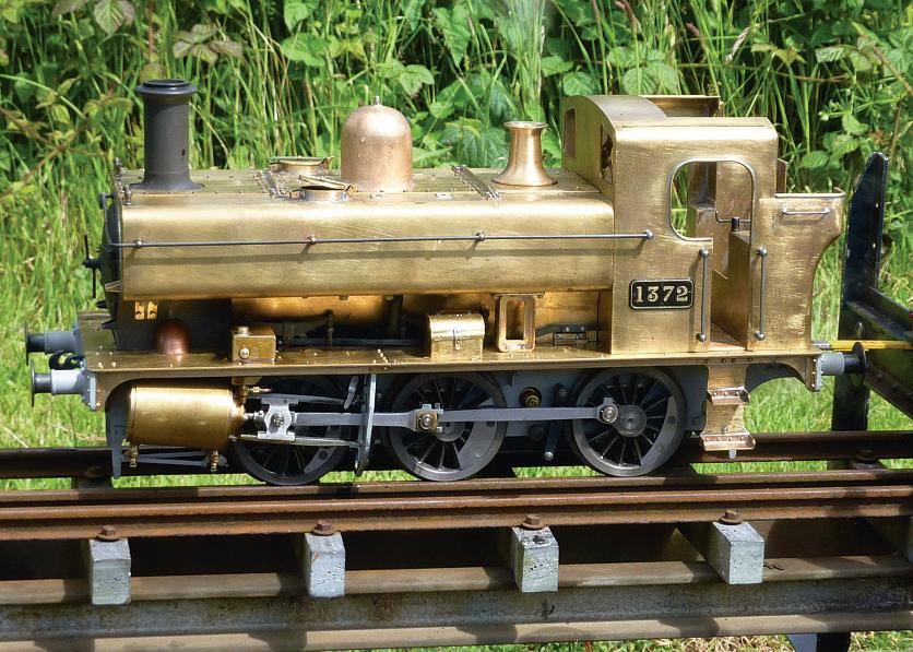
560 AGWR PANNIER TANK IN 3½ INCH GAUGE
Gerald Martyn buildsa 1366 Class locomotive from worksdrawings.
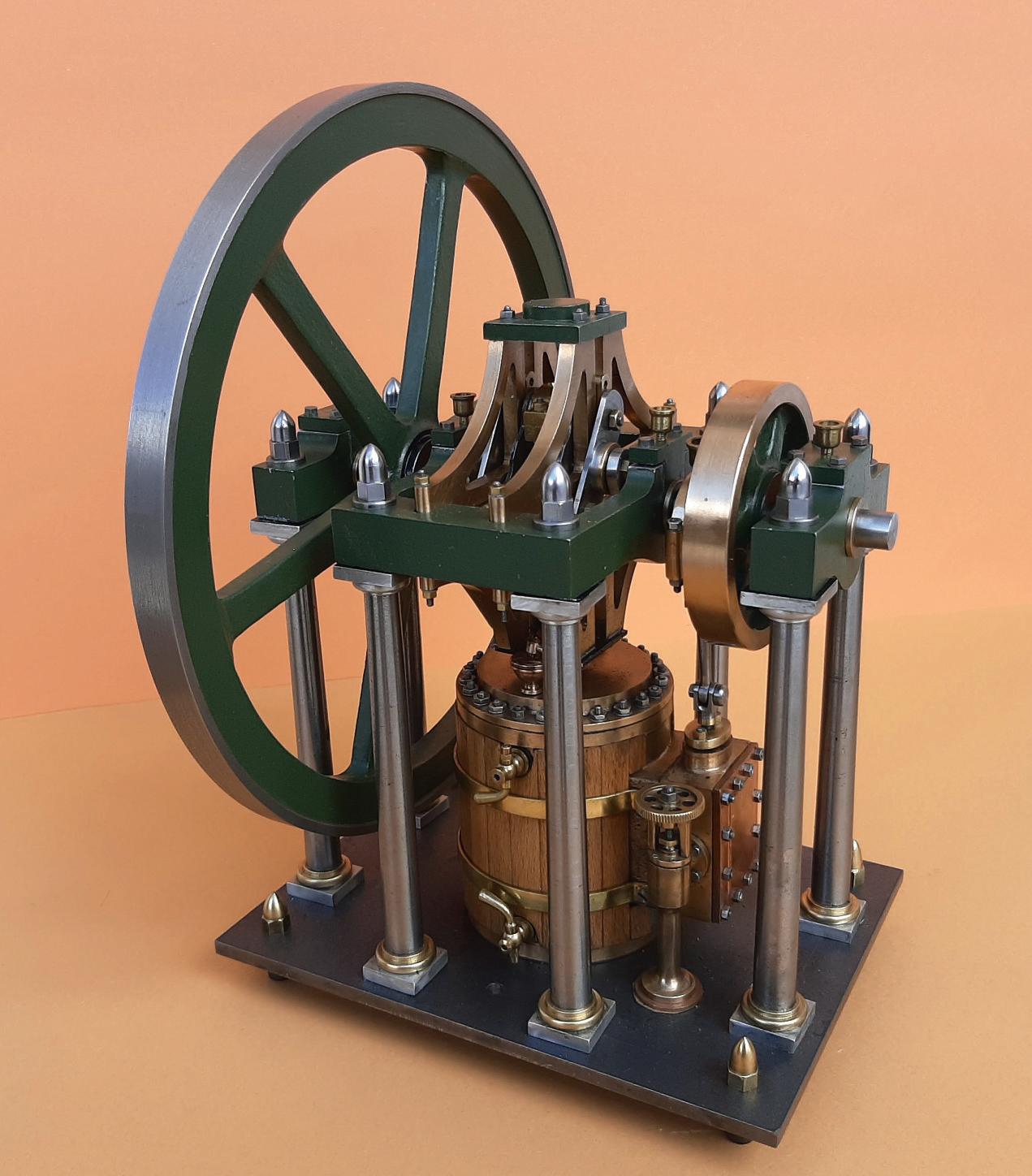
563 UNSEIZINGA BEAM ENGINE
MitchBarnesrestoresa nicely made but neglectedbeamenginetoworking order.
566 ADROPLINKCLOCK
Neil Carney borrowsfroma beam engine design to make an unusualclock
569 THEDEVELOPMENT OF MOTORCYCLE ENGINEERING BEFORE WWI
PatrickHendradiscusses thedevelopment of theearliest motorbikes
LesBrimson (North London SME) was awardedthe AustralianAssociationofLive Steamers Trophy at therecentFMESRally forhis 5inchgauge SECR LClass 4-4-0 locomotive forworkmanship,finish and detail (photo:MikeChrisp)
This issuewas publishedonOctober 18,2024. Thenextwill be on sale on November 1, 2024.
ST ALBANS
MARTIN EVANS Editor
Over thelastseveral yearswe have unfortunatelylostmost of ourmajor national model engineeringexhibitions
DIANE CARNEY Assistant Editor
Thelastshowrun by this magazine,for example, wasthe 2016 show at theBrooklands Museum.Since then we have lost theAlexandra Palace andHarrogate/ Doncastershows,which leaves rather sadgapsin themodel engineer’s diary. TheMidlandsshow, this week, is currently theonlyregular national show still on the calendar.Fortunately,a number of clubsrun theirown shows andsomeofthese aremost impressive,matchingthe scale, even,ofthe bignationalshows. Oneofthese is theBig St Albans ModelShow, runby theStAlbans& District MES at theTownsendSchool in St Albans.I wasfortunate enough to attend theshowa couple of weeksago andfound avery wide rangeofexhibitsthere Therewas alarge display of boatsand an impressive collectionofMeccano models, includinga nine foot long modelofthe USS Missouri, complete with revolvinggun turrets.There wasa largeroom dedicatedtoradio control trucks andmanymodel railway layoutsofvarying gauges Therewerefew locomotivesor traction enginesofthe larger scales or gauges buta good collectionofgauge 1and 2½ inch gaugeengines androlling stock. Trainrides (free!)were availableoutside andinside therewas a7¼inchgauge tracklaidalong alongcorridor, providinga ‘drive it yourself’ experience,which wasvery popularwiththe youngsters
Theshowhas runa couple of timesrecently(2020 and 2022) andI hope it will become aregular event(perhapseven annually?).I cancertainly recommend avisit
LOWMEX
Mar tin Evans can be contacted on the mobile number or email belowand would be delighted to receive your contributions, in the form of items of correspondence, comment or ar ticles. 07710-192953 MEeditor@mortons.co.uk
If youmissedthe St Albans show,there is still the Lowestoftshow(‘LOWMEX’) to come,witha similarlybroad rangeofmodelstosee. It hasbeen running forseveral yearsnow andgoesfrom strength to strength.It’san extensiveshow, rivallingthe former national shows. If you liveanywhereinornearEast Anglia Ibelieve it is a‘must see’.The show will be on the weekendofthe 2ndand 3rdof November at theEastCoast College,Lowestoft.More details areavailableatwww. lowmex.co.uk
LOWMEX
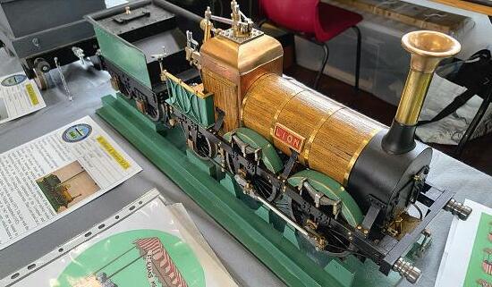
Afine 3½ inch gauge Lion,built by BrianStringer.
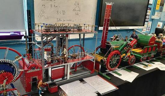
Part of theveryextensive Meccano display.
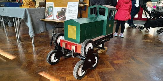
Mike Joseph’s Zahia,a battery electric loco on hertransport trolley, as featured in ModelEngineer (M.E.4716, May5th 2023)
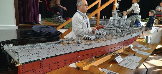
USS Missouri in Meccano,built by SteveBriancourt.
SUBSCRIBE ANDSAVE
Enjoy12monthsfor just £68
PRINT
ONLY
PR
Quar terly direc tdebit for £19
1year direc tdebit for £68
1year credit/debit card for £74
INT +D IGITAL
DIGITAL ONLY
Quar terly direc tdebit for £22*
1year direct debit for £85*
1year credit/debit card for £88*
1year direc tdebit for £50*
1year credit/debit card for £54*
*Any digital subscription package includes access to theonlinearchive.
>> Free UK deliver ytoyourdoor or instantdownload to your digital device
>> Save moneyonshop prices >> Nevermiss an issue
>> Receiveyourissue before it goesonsale in the shop
Brus hless DC Mo tors hles sD CM ot ors
Jon Freeman explains thebene ts f usin thelatestelectric t r techn l y
Longago,Somersetteam
Julie andJon joined the localmodel engineersand starteddriving theirPolly steam locomotive on theminiature railway in alocal park,giving ridestothe public afew times amonth during thesummer.
DrivingPolly in thepark wasfun buttoo much time wasspent keepingitclean andingood workingorder Maybeanelectriclocomotive couldbea time saver. Critical eyes were cast over visiting electrics, inspiringthoughts aboutcreatingsomething robust andtohighstandards -a lowmaintenance design, to be more reliable andmore effcient than thenorm, using more up to date technology This ledtothinkingofusing modern brushlessmotors, rather than oldstyle carbon brushedDCmotorsseen in otherlocomotives.Withonly twobearingsand no other moving partsincontact, brushlessmotorsare inherently more compact, effcient and reliable. They’realsoquite different,a littlelikea DC
motorturnedinsideout with some partsthrownaway, the magnetsonthe rotorwith thewindingsclosertothe outsideonthe stator.Often calledbrushless DC motors, it’s more accurate to thinkof them as permanentmagnet synchronousthree phase, AC motors,and we’llneedsome newelectronics to make them work at all.
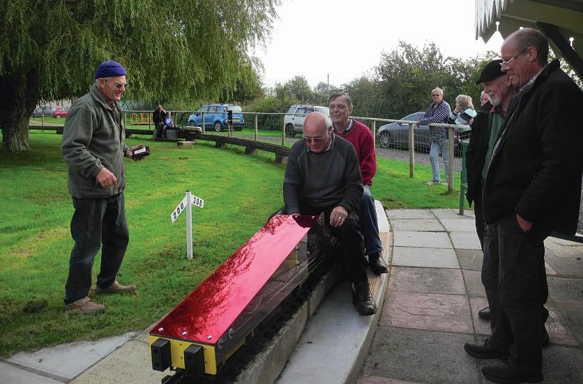
TheWedge wasthe frst fve inch gaugebrushless electric locomotive to emerge from theworkshop, nearly adecade ago, thedesignbrief being to producea locomotive ‘not less powerful than thePolly’. Photograph 1 showsrespected steamexpertGeoff Staitquite enjoying atestdrive at West Huntspill in October2015.As aregular runnereversince, TheWedge hasgiven hundreds of hoursand hundreds of milesoftrouble free service. With grease packed roller axle bearings,the minimal maintenanceregimehas been an infrequent look foranything coming looseand adropofoil to eightplain bronze bearings.
Powerisfroma pair of 50 amphour mobilityscooter batteries. Theseremainpermanently ftted, with asocketprovided on thecontrol panelfor a scooter charger. Observing astrictroutine of recharging immediatelyonreturnfrom anyoutinghas kept theoriginal batteries in usable conditionall this time
Theelectronics used in TheWedge were designed andassembledtoprove the effectivenessofbrushless motors anddrivesand as aplatformfor further development. As such,cost effectivenesswas nota particular considerationand thewhole construction cost wasa littlehigherthanfor similarlypowered kits or readybuilt locomotivesavailableat thetime. Theeconomiccase ever sincehas been constantly moving in favour of brushless designs.
At arecentspecial eventin thepark TheWedge wason duty fora full sevenhours Although theacrylic body shell does aperfect jobatkeeping
GeoffStait driving Wedge at West Huntspill.
waterout from above, wheels on wetrails flick rustynastiness up inside soakingsomeofthe exposedelectronics within This is aknown issueand a fewtimes an oldtoothbrush hasbeen used removing rusty crud deposits.After abrief rain shower that afternoon, performancehad become ‘a bit jerky’,dirty waterhavinggot to whereitshouldn’t.Lifting the body shelloff, andrunning the next fewlapsletting theair get in to dryitall soon haditback to normal.
Aquestionoften asked“how long do thebatteries last”? We cannow honestly answer -“sevenhours,or maybemore”.Regular public running sessionsare normally only threehours andother electricshaveoften bowed outinlesstimethanthiswith failingbatteries.Itissurprising howmuchmoreeffcient brushlessmotorscan be
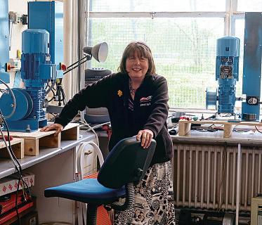
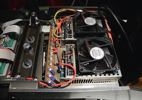
construction at themoment is alocomotivetoexternally resemble a‘Baby Deltic’. This is aonce-in-a-lifetimeattempt at proper modelling, with theaim of buildinga reliable hard-working,ratherthanfnescaleshowcaselocomotive. With no volunteerscoming forwardtoproduce aworking scalemodel of aNapierDeltic T9-29ninecylinderengine, thepower source will be a commercial700 watt petrol inverter-generator poweredby a40ccsingle-cylinder fourstroke petrol engine.Thisjust aboutfts,after taking very minorliberties with scale. The240 volt AC from this is converteddownto27voltDC usingtwo VOF-350 industrial powersuppliesfromFarnell (photo5). From thereon, the ‘frstfx’ electronicsusesall thesamekit as in TheBrute with modifcations to make the locomotive radiocontrolled. 2 4 3 5
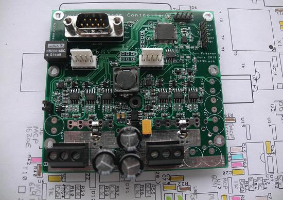
Buildinguponexperience, a second brushlessdesign, The Brutalist or Brute,followedon twoyears behind TheWedge This petrol-electrichas two sets of bogies to runonfve or seven-and-a-quarter-inch gauges Photograph 2 shows TheBrute sporting fveinch bogies at Vivary Park,Taunton Thepower unit is a120cc Hondafour-stroke engine drivinga 2kWbrushless motor as agenerator.Thishas proved to be quitesuffcient for heavy-duty work on thelarger gauge, having performedsome public running at Ashton Court Railway,Bristol.New electronic motordrivesand controllers were designed with aview to making them available commercially.Each Brute bogie is fttedwithone STM3EMC dual brushlessmotor driver controller(photo3). This keeps thewiringtidyand makes foreasybogie removal. Both
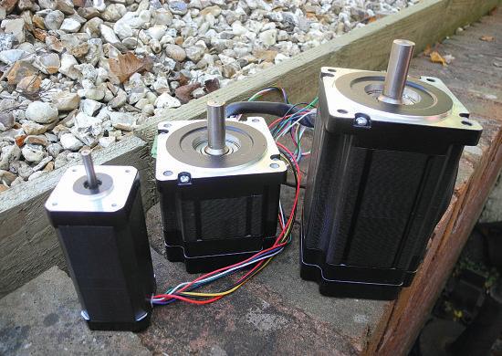
locomotivesare driven by ‘touch-screen’and both usethe ‘six-step’ algorithmfor motor drive. Photograph 4 showsthe motors used in TheWedge,and in both bogiedesigns of The Brute.Theyare ratedat105, 220and 660wattrespectively. Beingquite bigand heavy, TheBrute doesn’tget toomany outingsbut it hasa perfect reliabilityrecordtodate- start theengineand go By design,neither of these locomotivesbears any resemblancetoany mainline prototype. Toooften huddles of gricershavebeenseen gatheringaroundsomeone’s prideand joy, stroking their chins, mumblingand tutting abouthow awfully wrongitall is.Thankfully,mostofthese miserablewretchesare so appalledatthe sightof Wedge and Brutalist,theytendtokeep well outofthe way. Good! Breaking with tradition, under
TheBrutalist at Vivary Park Taunton.
Motors used in Wedge and Brute.
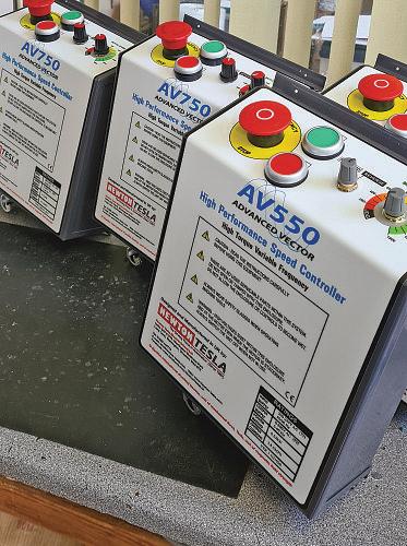
STM3_EMC dual brushlessmotor controller.
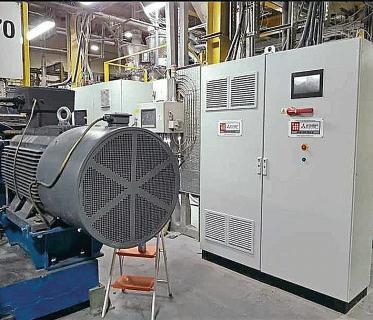
Baby Deltic powersupplies.
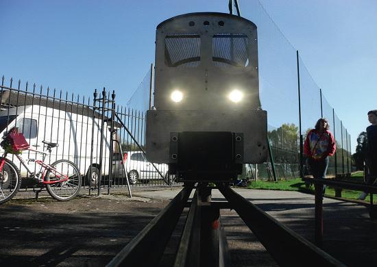
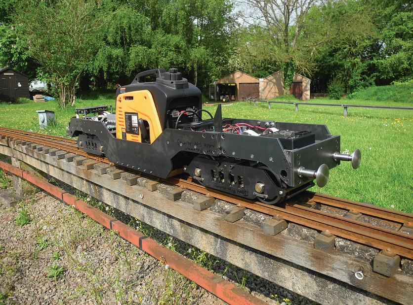
This is thesameascurrently used by TimColes in his 18100 turbineloco. TheBaby Deltic is nowfully working, andcompleteexceptfor the body shelland 3D printedcabs (muchmoreonthese in a future article!). Thechassis has successfully completedtest runs at Bristol(photo6)and Taunton.
Still somethingofa novelty tenyears ago, brushless motors arerapidly sweeping theboard,relegatingbrushed DC motors to ‘dinosaur’ status throughout industry.Alongside this,the electronicsindustry hasinvestedindevelopment of many highly integrated,low cost motordrive solutions. Afresh look at this latest technology encourages adoption of simplifed,higher performance, lowercost controldesigns forthislatest locomotive
An importantstepinthe processofdesigning for reliabilityisinunderstanding likelymodes of failureand their consequences.Locomotives of thesescalesmay take harsh treatmentand we coulddraw up alistoflikelyfailures: seized axle,shorted or broken wires, slipping drivecouplings –and
doubtlessmanyothers.
With minorvariations, all otherlocomotives seen have been confguredasshown in fg 1,a number of brushedDC motors wiredtogethertoa single powercontroller. This mayworkwellenoughwhile everything runs sweetly with motors sharingpower equally between them butthere is little or no resiliencetoany likely failures. Theweaknessisthat anyfault will upsetthe balance, whichhas consequences
Astalled motormay draw a much higher than ratedcurrent leadingtodamageorburnout. As anotherrealexample, recently on theclubtrack a twomotor locomotive was seen trailingplumesofsmoke Somehowone motorhad become disconnected,allowing twicerated powertocook and burn theother.Which ever way we look at it,the open loop, single-controllermulti-motor modeloffg1 is unreliableby design
Figure 2 illustratesthe design topology we aremoving towardsinusing brushless motors.Eachmotor works with itsown intelligentmotor drivecircuit,consistingofsix powertransistorelectronic
sendsdigital commands to themotor drives,which mayrespond with status information. Anyalarm or problemmay then be displayed on thelocomotivecontrol panel.
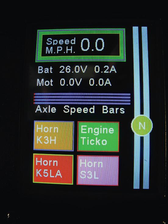
On TheWedge,for example, thecontrol paneldisplay includes asimplequadbar chartsection (photo7). This indicatesthe measured speeds of each of thefourmotors. The occasional glance while driving to seethemall aboutthe same is suffcienttoknowthatall’s well.
switches providingmotor powerand amicrocontroller overseeing operations.Any motorproblem is managed locally andsafelywithinits owndriver, withoutaffecting anyother motors or motor drives.All of this with virtually no chance of letting anysmoke out. Thelocomotivecontroller hasbeen simplifed by shifting allthe powerelectronics closer to themotors, while capability hasbeen included fordata communications. Modern microcontrollers come with aselection of inbuilt data communication methodsand theone chosen forongoing work will be ‘CAN Bus’.The locomotive controllernow
Thebrushless motors used have eightwires:three heavy wiresfor themotor power phases andfve fner wires to do with threeinternalHall effect sensorswhich provide informationtothe motordriver aboutthe motorshaft angleat anyinstant.Not allbrushless drives usesensors butthey areessentialtothe ‘six-step’ algorithmthatworks very well forour purposes.Itcan be a littlepainful routingall these wireswithina locomotive but as motordrivesget smallerso it becomeseasiertomount them on,oratleast closeto, themotors. This localises and keepswiringtidy, individual motordrivers then beingeasily connected together andwired to thelocomotivecontroller. Back in 2018 theSTM3EMC dual brushlessmotor controller wasreleased. Designed using generalpurpose electronics of theday,these boards used quitea largenumberofsmall components andoffered littlechangeout of ahundred pounds permotor.These are used in TheBrute,and in the
Baby Deltic test runatBristol
Dinosaur DC motors
Fig 1
Baby Deltic to startwith. Selling in admittedlysmall numbers, reliabilityhas proved to be good with none ever being returned forany reason.Get outthe locomotive,dropiton thetrack andhit thecontrols. It alljustworks withouta worry Thelatestadvances in electronicsprovide
signifcant cost andspace saving opportunities. For example, measuringonly 9mmsquare, theSTSPIN32G4 system on achipoffering from ST Microelectronics comprisesa high performance microcontroller, together with othercomponentsoptimised formotor drivers. Even in
Fig 2
forvoltage,current andspeed areset.Thisprovidestotal motorprotection, from the electrical side at least. Aset of variable ‘working limits’ areusedinmotor control. Theseworking limitsmay be individually settoany value from zero to themaximum limit set. This enablesa vast choice of controlmethods,someof whichmay be useful in traction applications
smallquantities, it costsabout thesameasa pint down thepub.One of theseona circuitboard with sixpower switchingtransistors,and asprinklingofother small components,and we have all thehardwareinplace.Withon boardconfgurationmemory, motors will be driven safely within manufacturers’ limits, while monitoring performance andrespondingsafelytoany abnormal or faultconditions. This motordrive hardware, once proved on thebench,will be built initially into theBaby Deltic andtoupgrade The Wedge and TheBrute in due course
Buildingelectronics using thesetinysurface-mount components is no longer a realistictaskfor thehobbyist. The9mm square controller chip has64connections with a 0.5mmspacing andthey’re all underneath,where youcouldn’t geta solderingironevenifyou wanted to!Fortunately there’s alocal companywithall the proper kitwho canassemble circuitboardsfor us at a reasonable rate
Notmuchworks without software thesedays, motor driversincluded, andover time alibrary of useful motor controland traindriving code hasbeen built,incorporating alot of good feedback from users. This includes theidea of ‘driving to limits’.Inthe motordriver, maximumvalues
Forexample,withany two of thesevariablelimitsset to maximum, thelocomotive canbecontrolledbyvarying thethird between zero and max. This opensthe wayfor new, possiblybetterormore interesting, ways of driving. Forexample drivingbyvarying thevoltage limit givesa drivingexperiencesimilarto that of aclassicdinosaurDC motorand controllersetup. Drivingbyvarying thespeed limit is similarrequiring even less driver brainactivitybut arguably more interestingis drivingbyvarying thecurrent, or torque,limit.Thisgives an altogether different feel giving thedrivermoreofa sense of what’s beingasked of the locomotive.Withtorquelimit driving, thedriverwill need to setthe controlhighwhen pullingawayorclimbinga gradient andmaybe turningit down to zero elsewhereonthe track. It wouldteach thedriver somethingabout thetrack if nothingelse.
Work is proceedingtowards getting thenew motordrive electronicsrunning the‘sixstep’algorithm so that new controllers canbealmost seamlesslyretro-ftted. This leaves scopefor future developmentofsoftware usingother algorithms to possiblysqueezea littleextra performanceand effciency. With no spaceleftinthe shed,there will be no more locomotivesafter Baby Deltic 5 91 4. This last one’sfor Julie
Safe brushlessmotor scheme
TheWedge displayand touchscreen
AG WR Pa nn ie rTank in 3 ½I nch Gauge
Gerald Martyn decidesto build alocomotivethat he canlift.
Continuedfromp.517
M.E.4753 October4
Frames
Just to show howlittle informationisneededbythe laser, whichgetswhatitneeds from thedigital shape, fg showsa visual representation of themainframe plates I’ve just givenone dimension
to help scopethe size of thejob andeventhisisnot essential. Just think, also,of allthe drawingoffce time savedbynot dimensioning everyfeature on this drawing andhow cluttereditwould become.The frames need a
bitoffnishingbeforeftting andfnalmachining of the horns. Thelaser cannotcut smallholes,sothose down to about0.108 inch (2.75mm, 5BAtapping size)shouldbe there, butfor smallerones thepositionwillbeaccurately
Frameplate holeskey
A= Ø1/16" forrivet
B= Ø2.5mm for7BA fastener
C= 0.110"/2.8mm for6BA fastener
D= 1/8" for5BA fastener
S1 =7BA thread
S2 =5BA thread
COF= countersinkouter face
Drillingdetails forthe frames
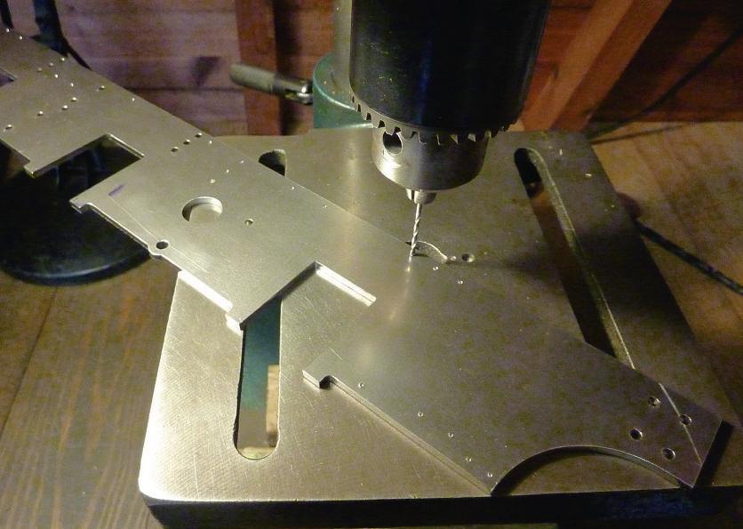
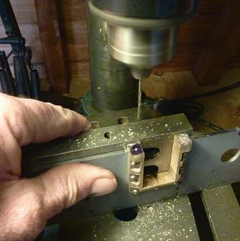
markedwitha smallcross. The frames generalarrrangement with thesideviewgivingall thedrillingand thread tapping informationisshown at fg Otherinformation is givento aidmachining thehorns after they have been fttedbut for nowthe task is to drill the holes, tapthe threadsand cut thecountersinksinaccordance with thecodeletters givenin theholes keylist. Centre punch at theexact centre of allthe littlecrossesonone frame only
g showsthe frst pilotholeofthe threefor thereverserwhich areinthe right-hand frameonly. Pilot hole?It’scommonpracticeto startwitha smalldrill which will more certainlypick-up in thecentre-popmarkand will also remove thebit in themiddleofthe hole where alargerdrill hasnoproper cutting edge.(Note:Photo 6 is an illustration andmyspare hand is holdingthe camera;I’d normally hang on to thepart
Cutout to clearboiler rear hornsonly
FramePlates
HolesØ3/32",COF
Drill to suit horns
Scrapview showingguard iron offset
UseØ3/32” rivets,heads on innerface
Note FWD3 on rear horns use7BA CSKscrews
theframestogetherusing 6BA boltsand drill throughbothas apair. Separate theframesto
sections andare abit delicate untilassembled andare easily bent.Theymay also be abit curved anyway.Justbendthem straight,ineitherevent.When fully assembledtheygainlots of strength from theother partsand,later,fromthe parts that will be bolted to them, particularly thesmokebox.
Adigression now, about holesand threads. Lasercut holeswillgenerally be ‘si e’ unless reamingiscalledfor,in whichcasetheyshouldbea fewthou. under. Forthreads I always usethe recommended tapping sizes, whetherdrilled or lasercut.Thisensures a decent thread withouttoo much chance of breaking a tap. Thethreadclearance sizes givenindatatablesare rather arbitrary. To ease assembly they allowfor some notional mismatch between theholes on twoparts beingbolted together,soare oversize and give arathersloppy ft.I prefer to useclose clearanceholes and, with theaccuracy of laser cutting,the partswillalmost always assemble.I also hate to buyspecial sizessouse what is in astandarddrill set whenever possible. So,for say B fastenersI fnda 7/64 inch drill will just do and have specifed diameter 0.110 inch forlaser cutting.Ifparts will notassemblethenyou canalwaysrun alargerdrill throughand be no worseoff than if usinga sloppy ft si e in thefrstplace.For larger clearancethanwiththe small BA sizes, thetapping drill from twosizes up will generally do quitenicely. Tapping threads
in smallholes canbea bit worryingbut normally if you just back-off half aturnor so,assoon as thereisany increasedresistance, to break thecutting chipsaway, allwill be well.Whentapsbecome worn (moretorque, more friction when reversingout) then throwawayand replace. I’ve nothad much success with proprietarythread-cutting lubricants in thesesmall sizes butbychancefound that Stihl strimmergearbox grease ‘SuperlubFS’ worksreasonably well formostmaterials, includingcopper.
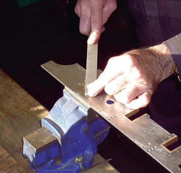
On with thestory.Withall theholes fnishedthenit‘s timetodress offall thesharp edgesand remove thelittle pips wherethe laserstarted andstopped. This is simply good practice.Parts will not assemble properly if thereare sharpedges andburrs sticking out. Iuse asmall flatoval needle flebut specialtools areavailable. Forholes then a fngerand thumbtwirl with a larger size drill usually works. Do thesethingsoneverything butI’llprobablynot mention them again.
Theframesare nowready to have thehorns ftted. There areeitherseven 3 32 inch rivets needed foreach, or four rivets andthree 7BAscrews at therearaxlepositions. ole positionsneed to be worked outbecause castingvariability precludesprecise locations forall.Theyalsoneedtobe countersunkonthe outerframe face to give aflushsurface but notsodeeply that therivet tails cannotbehammeredintofll
thespace.It’sgood practice to puta layerofsomething between permanently assembledparts andI gave theframe alocal spraywith primer.Fit a3 32inchrivet throughfromthe horn side,clip it offshort andhammerthe tail to fllthe countersink. epeat Therearpairofhorns have three7BA countersinkscrews each,fttedintocountersinksin theoutside face of theframe Theseare as permanentasthe rivets so areassembledwith octite 03 to lock andfll any voidsand thetails cutoff flush with thehornrebate. Aquick cut-offmethod(no doubtI’ll gettoldoff forthis) is to usea second-bestwoodwork chisel, placethe cutting edge on the screwatthe horn face,and give thechisela sharprap with ahammer. To fnishoff then, fleall thecountersunk rivet tails andany protruding horn edgesbackflushtothe frame ( ).
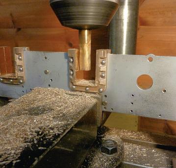
To machinethe slotsfor theaxleboxes theframesare bolted back together,outer face to outerface. This is never an easy task andthistimeI foundmylongmillingcutter hadgoneAWOL, so adding to thediffculty.Intruth,I’ve nevermanaged to geta good fnishbymachining with an endmill or slot drill, as they’re simply notdesignedfor this sort of job, buta bitofcareful flinghas always sorted things outand didagain this time.It wouldbefar bettertouse a horizontal mill with anicebig side andfacecutter, butI don’t have one. Firstget theslotto theright depth, then attend to
thewidth g shows onecutterpass, forinterest. Itakeshallowcutssoasnot to risk displacing thehorndue to thecutterforces. This can happeninspite of therivets. On thedrawing I’ve putsome referencedimensionswhich canbemeasuredwitha digital caliper (anyonestill usinga vernier?)tolocatethe slots. Measurethe dimensions to severalpositions in theslotto fndthe ‘least metal’ position anduse that as theguide.After allthe slotsare done,thenthe best time to carefully take off thehighspots is when theaxle boxesare ftted.
The6BA holesinthe horn toes see fg 3 Part 2, M.E.4 53, October4 come next and showsthe drillingoperation with the frameheldagainst an angle platetoensuresquareness. Lastly,rivet on thedrain-cocks brackets,which should be on theinsidefaces,and bend and rivetthe guardirons,which should be on theouter faces. This took longer than it should becauseI hadsomeofthose infuriating1/16inchrivets whichare actually made from 16 SWGwire, so of course don’tftinthe holes. opefully my next purchase will be right. Theframescan nowbeput asidefor awhile *Loctite;another innovative Britishcompany nowinforeign ownership. Iconsiderthattheir anaerobicproducts, likeLoctite 03, arestill thebestavailable.
To be continued.
ilingthe horn retainingrivets ush.
Millingthe horn slots.
Drillingthe horn toes
Unseizing a Beam Engin e
SMEE’s
Mitch Barnes gets to gripswithanMEBeam Engine steamplant, which hadbecomeseizedupat some pointinits past.
This series is atranscript of atalkgiven to theEngine Builder’s Groupatthe Society of Modeland Experimental Engineers(SMEE) in May2024.
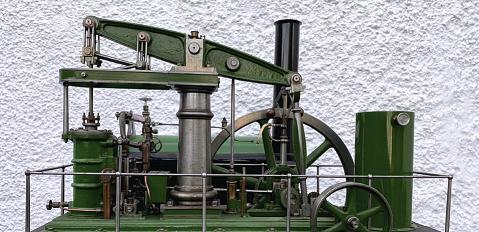
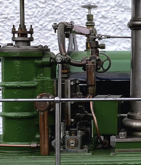
Abit of background Firstofall, I’dliketoshake the hand of thegentleman who built this steamplant (photo1). It is withoutdoubt oneofthe fnestexamplesofthispopular design that Ihaveeverseen It wasthe work of aMr. L. J.
Evans, in 1981, andunlikemost modelenginebuildershewas wise enough to puta neatly engraved makers plateonto thebedplateofhis creation.If anyreadercan tell me where he built it andifheisstill around,and even to introduce me to himfourdecades later, I’dbedelighted to make his acquaintance.I wonder if he wasfamiliarwithfullsized stationary enginesasthis onepossessesa mechanical lubricator forthe cylinder and acrankpinoiler, somethingI’ve rarely seen on amodel outside amuseumand oftenpresent on therealthing.Thissteam plantwould have wonawards at SMEE! I’ve always felt the ModelEngineer Beam Engine andits larger sibling, theMajor Beam Engine to be handsome beasts anda steamplant built around either onewould be a lovely thingtohave, so to be
PA RT 1
able to getthisexample going againshouldbea particularly rewardingexperience.
Theenginewithits neatly enclosed Stuart 504boiler came to me freshfroman auction. Thepurchaser knew from theauction description that theenginewas seized,a problemI have seen before on modelsteam engines. Often this is theresultofhavingbeen left with waterinthe cylinder aftera running session butmy frst encounterwithitwas when aged 11 or so,and knowing almost nothingabout anything driven by steam, Ibought with pocket moneyanold Bowmanoscillating potboiler toywhere thepistonhad been gluedintothe cylinderwith Araldite!Defeatedbythisbut notcompletelydaunted,I soon graduatedtoMamodsand had quitea fewbeforeI left school My friendsand Ienjoyed
SMEE
heenginesportsso enicedetails,all of hichhavebeenfinely executed
running ourmodelstogether andwhile they went onto other things,for me,the steambug wasinstilledinmebythose experiences, though acareer in retail andthencommercial model-making caused it to be latent foralmosttwo decades.
Forreference,the Model Engineer Beam Engine is a1/12 scalemodel,soanadult person wouldbejustunder 6inches tall standing next to it its larger butotherwise identicalversion, theMajor,was stated as 1/8 full size by George Gentry back in 1914, so afgurine in scale wouldbeabout 9inchestall. TheMEcould also credibly pass fora 1/16 modelasit’s arepresentationofa small beam engine,evenbysingle column standards. Lookingat theheightofthe railings,I think Mr.Evans assumedthistobe thecase.
Butfrstlet’s take aclose all roundlook at theplant andsee what it hastooffer. Theinitial impression is that it exhibits excellent attentiontodetail, atrueexample of thephrase ‘… themoreyou look,the more yousee’ (photo2). For instance,lookingatthe pinion shaftwiththe pulleywheel
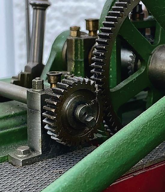
placed across thecrankshaft endofthe bedplate most examples I’ve seen ust have a plainpinion, possiblysecured with agrubscrew acting on asimilarly simple crankshaft drivecog,bothwithflat blank
faces. This oneistrueto full-size practice,havingbeen radially waistedand is keyed to theshaft in thecorrect manner(photo3). Similarlythe drivewheel on thecrankshaft is as clockmakerswould say
‘crossedout (pierced to create shaped spokes)ratherthan beinga blankfeatureless disc
Youcan hardly seethe pinion,sandwichedasitisnext to theflywheel,sohavingthat detail on it is an indicatorof
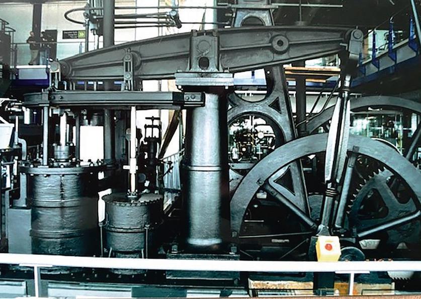
No youare notdeceiving yourself here –thisistwo enginesconnected together with
iron gear
Engine, an 1820 engine coupleduptoanother 20 yearsyounger.Inuse until1943, they must have been deafening!
Even thebarelyvisible pinion wheel hasbeen correctly shapedand keyedinplace
cast
wheels; TheBurmanDouble
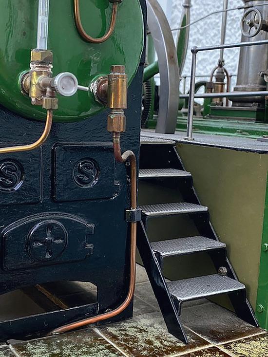
Anicely adeset of stepstakes oneuptothe Bea Engine’s cylinder oor
thecarewithwhich thewhole steamplant wasbuilt
To be honest,the crossshaft lyingoverthe bedplate is,to me,a visual offenceagainst theGenevaConventionasit’s such alash-up,but this kind of arrangementwas notunknown Ihaveseen such in full size though,notably the‘Burman Double Beam Engine’(now at Birmingham’s ThinkTank Museum). This interesting double,painted all-over black, wasphotographedwith diffcultyona dull dayin2003 (photo4 Ihopeit’sstill there. ThelargerA-framedengine behind datesfrom1820 and wasatsomepoint coupledup usingcastirongearwheels to thesmallersinglecolumn engine of 1840 -makers unknown. They worked rolling mills at WychallMill in Kings Norton,Birminghamuntil 1943 –a long-lasting lash-up! Butlasttheydid,evenwiththe repairstothe smallerengine’s spoke rim ointsonits flywheel. With thoseironwheelsclanking around,working with them
into this project. Rather than simply aboilerand an engine with perhapsa manually operated boilerfeedpump bolted to aboard,heput this set-up into context, to represent, within thelimitations of spaceand practicalityfor running, arepresentative industrial setting that would give theplant areasonto exist. e maywellhavetaken inspirationfromfullsized installations. Others in thepast have placed theirengineand boilerlikethisbut Mr.Evans took it to anotherlevel with his attentiontodetail.
With theboilerplacedon thefloor,the engine resides alongside, on aprototypical raised floor whichalsogets around thepotential problemof accommodating theflywheel. Access to theenginewould be gained by theneatlybuilt steps leadinguptothe walkway whichsurrounds theengine. This is nicely executed with chequer-plateflooringand a barrier of fnelymaderailings (photo5).
musthavebeen deafening!
Pardon?Atthe time of viewing they couldbeturnedoverbyan electric drivewhich thankfully, wasfairlyquiet.
George Gentry’s original 1914 articles detailingthe construction of what is now knownasthe MajorBeam Engine,ofwhich theMEis a2/3 scalereplica,brought forthsomederogatory correspondenceabout the crossshaft and, giventhe choice,I’d remove it entirely On theplusside, it does give theMEorMajor Beam Engine a senseofalbeitclunkypurpose and, alongwiththe governor, is anotherpartofthe engine that onecan observetwiddling around when theengineis running,I suppose.Suchthings canappeal to thoseuninitiated into theMysteries of Steam andcould generate future interest just as thoseMamods didfor me
L. J. Evansevidently wanted to give this steamplant an expression of purposeand must have puta lotofthought
Whatever hisbackground he wasa fneengineer with agood eyefor detail andthe abilitytobring it to fruition even therailings aresuperbly executed,eachabsolutely identicalstanchion with entasis on itsshaft andthe railingitself preciselycentred on each one in aperfectly shaped ball.
Iconfess that Iamless enamouredofthe watertank at thecrankshaftend of the engine butthisisanother pointofinterest: this steam plantwas evidentlymeant to entertainand educatewhile it wasrunning andthe water pump,operatedfromthe crankshaft side of thebeam constantly circulates water into andout of thetank, adding more interest.
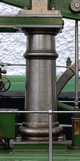
aving atinysmattering of architecturalknowledge, it always grates to me to see thetori(those‘doughnuts’,to theuninitiated)atthe topand bottomofthe column only vaguelyrounded in section: this particular engine is amongthe frst I’ve seen wherethis ob hasbeen carried outcorrectly, both on thecentral column and
thegovernorcolumn. aving turned oneofthese columns myself,I canvouch that it’s thedevil’sown jobwhile you areturning thecolumn’sshaft That square plinth at the bottomand thesimilarlysquare entablatureatthe topofit, with thosesharp corners, offer thechanceofa potentially agonisinghazardwhile whirling around with abandonsoclose to your fngers andthe lathe tool.Formtools candothe job of course buttoturnthe lower toruswithone requires alathe somewhat more rigidthan theaverage modelengineer’s Myford unless nearly allthe donkey work hasbeen done in shaping, with theformtool taking care of thefnalcontour, duetothe pressuresofthe side loadsrequired. Talkingof which, also on this example thosetwo square parts- the plinth andthe entablaturehave been givena decorative recess alongtheir sides, allof whichlineupperfectly,those on theentablature marrying with the -shapedextension to near perfection (photo6).
To be continued.
Thecolumnhas itstwo decorative rings– knownastori– turned to near perfection.
AD ro pL ink Cl ock
Neil Carney pays homage to beam engine designer
J.H. Tattersall.
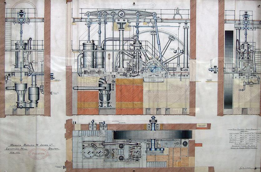
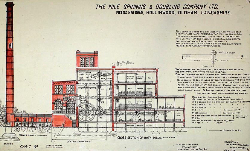
SometimeinJanuary 2021, during atelephone conversation with Diane, your AssistantEditor, whois also amemberofthe Northern Mill Engine Society, Imentioned that abeautiful,watercolour generalarrangement drawing of abeamengine, intended forEgyptianMill, Bolton,had come into thepossession of theBoltonSteam Museum and wasnow gracingthe museum wall (photo1). TheMuseum was, at this time,temporarily closed to thepublic,ofcourse. IsentDiane aphotographof thedrawing andshe asked me whetherI wasthinking of making amodel of it.My answer wasa defnite‘No ’ She then askedwhatitwas about this engine that particularly appealed to me andsuggested that Icould,perhaps,makea modelofjusta part of it -a part chosen to illustrate the uniqueness of this particular engine.
Theengineinthe drawing hadbeen designed by
Thewatercolour generalarrangement of abeamengine, intended forEgyptianMill, Bolton
2
Thelastand largestbeamengineeverput into acottonmill: Nile Mill in Hollinwood,Oldham.
J. H. Tattersall, aconsulting engineer of Preston, whohad been responsiblefor quite anumberofbeamengines forcottonmillsbut whowas nevera builder of engines himself. Hisdesigns,however, were rather unusualinthat allthe parallelmotionwas rectangularinsection with
3
boxend bearinghousings whichgavethema rather cubicappearance -quite outstandingincomparison to others.Tattersallalso designed thelastand largest beam engine ever putintoa cottonmill;thatbeing at Nile Mill in Hollinwood,Oldham ( ). It wasa twin beam
gave 2500 N.H.P. It wasbuilt by Buckley& Taylor of Oldham in 1899.Atthe time it was built,Nile Mill wasthe largest ring spinning mill in theworld I think thebuildingstill stands
Oneofthe drop links,which connect thelow pressure crossheadtothe beam end, waschosenasa suitable componenttoillustrate this design
engine with threecylinders giving triple expansiononeach beam,the H.P. beinginthe McNaught position,i.e.half waybetween thebeampivot andthe crank, with theL.P.and I.P. in thenormalpositions.It wasset ‘halfin- half out’ of themillascan be seen on the drawingand thesix cylinders
4
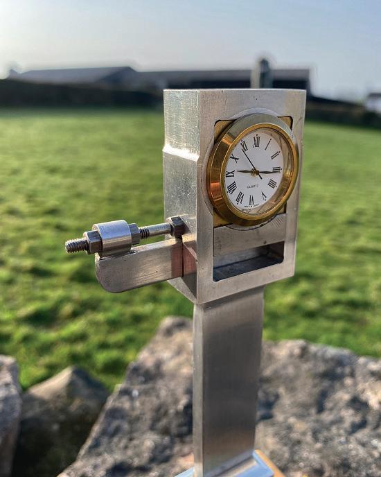
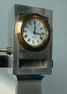
Thesizeofthe linkwas decidedbythe clockinsert whichhas a30mmdiameter bezeland abodydiameterof 27mm (photo3). This calledfor abox endwidth of 35mm and, from my photograph -taken by George Watkinsand published in hisbook of Stationary Steam EnginesofGreat BritainVol. 3(Lancashire Area)- other dimensions were estimated to keep them allinproportion. Theresultwas atotal length of 190mm.
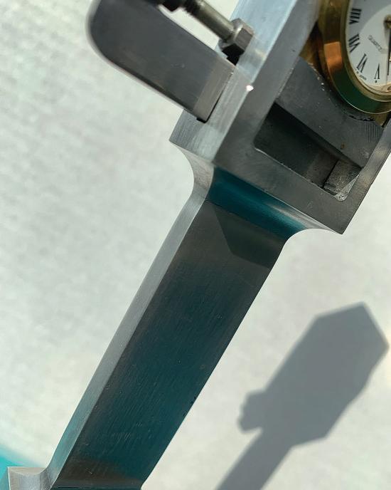
Thedesignrequiresa reducedsection at itscentre so this is aseparatepiece, attached to thebox ends by 4mmtongues andgrooves, securedwithLoctite (photo4). Thebox ends were made frst
The size of theproject -i.e.the link -was decidedbythe clockinsert.
(all in aluminium, by theway) both together.The blending 6mmradius, whichmakes a beautiful, eye-catching feature of this particular component (photo5), wasformedbya 12mmdiameterend mill. Before separating,the combined length wassome 130mmand machined down to 35 x18mminthe four jawchuck before millingthe housingfor the‘brasses’.This spacewas 25mm wide by 42mm long milledout with a
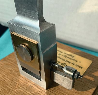
inch endmill usingstops on the millingtable slides both ways. Thecorners were squared offbyhandfling. Because the‘brasses’ only need to be correct in appearance they are, in fact,3mm thicksheet brass, 26mm wide,milleddown both edgesto25mmfor half theirthickness to locate in the housingbothsides andheldin placebythe headed steel pins, replicatingfullsizepractice, with areduced diameter inside andscrewed together.This
is fnefor thebottomend ( )but thetop endhad to be designed to take the27mm diameter clockbody(photo3). Only averyslight amount of brassisvisible at thefour cornersofthe clockbezel (photo7); asquareopenbox wassolderedupfrom25mm square outsideand 3mmwall. It wasnecessary to have this boxfttedintoits housingand fxed in placewithits retaining giband cotterarrangement priortoboringthe 25mm
hole forthe clock, whichonly needed to be adepth of 6mm (the depthofthe clockbody)
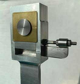
Thegib is 4mmthick so slotsfor this were milledinthe boxendsand thegib,which is thefullwidth of thebox end, 18mm. Thetaper of thegib and cotteris4 degrees.The cotter hasaneye silver soldered to itsouter endtotakethe 5BA retainingstudwhich is screwed into thesideofthe housing andthe cotteradjustmentisby thetwo 5BAnuts. Greatcare hadtobetaken adjustingthe cotterasthishas to grip the clockbody, aftersplitting the brassbox housing, duetothe fact that the‘brasses’ would tipslightly as they gripped theclock.The answer was simply astrip of brassequal in thicknesstothe gapbetween thebrassesand soldered into aslotcut into thedummy steel pinatthe back,thispin head matching theone at thelower end(photo8).
This ‘top brass’ assembly wasall fttedinplace and wedged with itsgib andcotter priortoboringout to 27mm.
Thethinkersamongst our readerswill realisethat27mm exceedsthe 25mm housing space This wasa problemat ‘frstdesign’ thoughts butit wassoon realised that,with theclock body beingonly6mm deep,thatwas as farasthe excess bore needed to go and it wascovered by thebezel
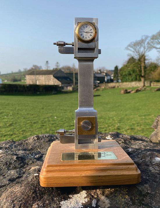
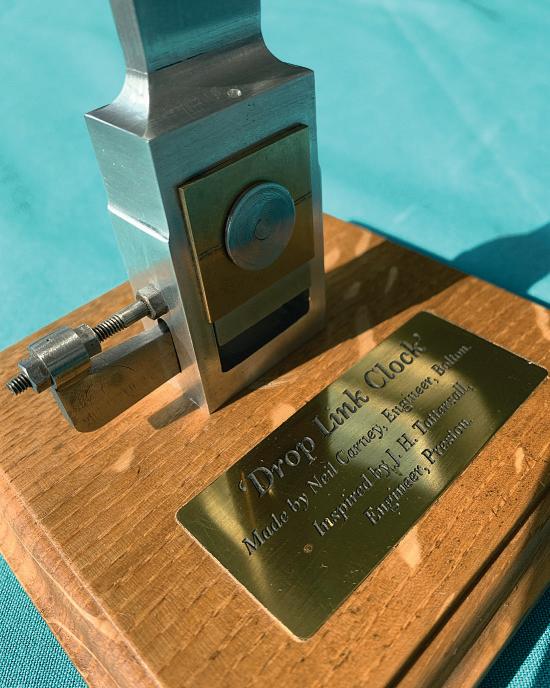
Some time waswellspent on thefnish of thealuminium anditisnow satisfactorily mountedona nice pieceofoak with beautifully mouldededges (photo9)- apresent from my granddaughter’s partner, Ben Roberts, asteam engineer with exceptionalwoodworking talents
Thebrass plategivingdetails was, of course,madebyyour AssistantEditor, Diane, whohas takenpossession of theclock Thewording on theplate is:
‘DropLinkClock’
Made by Neil Carney, Engineer,Bolton.
Inspired by J. H. Tattersall, Engineer,Preston
Acloserviewofthe ‘bottomend’.
Aviewofthe back -behindthe clock. Adescriptive pla ue andanoak base for thefinishingtouches
Theclock locatedinits ‘housing’.
A12mmdiameterend mill formed theattractive 6mmradiuses.