


Flywheel for atwin compound winding engine.





❖❖
Workinglamps forafive-inch loco Avisit to aclub by the Oxford canal. High-pressure engineby Trevithick Tenderbodyfor Cornwall EX PE RI ME NTAL EN GI NE AT CO AL BR OOK DA LE TH EO RI GI NA LM AGAZ IN EF OR MO DE LE NG IN EE RS Vol. 233 No.4745 14 –27June 2024 Join ouronlinecommunity www.model-engineer.co.uk
PublishedbyMortons MediaGroup Ltd,
MediaCentre, Morton Way, Horncastle,Lincs LN96JR
Tel: 01507 529589 Fax: 01507 371066
©2023 MortonsMedia ISSN 0026-7325 www.model-engineer.co.uk
EDITORIAL
Editor: Martin R. Evans
MEeditor@mortons.co.uk
Deputy editor: DianeCarney
Designer: DruckMedia Pvt. Ltd.
Club News: GeoffTheasby
Illustrator: GrahameChambers
Publisher: SteveO’Hara
CUSTOMER SERVICES
GeneralQueries andBackIssues 01507 529529 Monday-Friday: 8.30am-5pm Answerphone24hr help@classicmagazines.co.uk www.classicmagazines.co.uk
ADVERTISING
GROUPHEADOFINVESTMENT– Lifestyle& TractorPublications |www.talk-media.uk MasonPonti mason@talk-media.uk
A: Talk Media, TheGranary,Downs Court, YaldingHill, Yalding, Kent ME18 6AL Investment Manager: KarenDavies karen@talk-media.uk
PUBLISHING
Salesand distribution manager: Carl Smith
Marketingmanager: Charlotte Park
Commercialdirector: NigelHole
Publishing director: DanSavage
SUBSCRIPTION
Full subscription rates(butsee page 6for offer): (12months, 26 issues,inc post andpacking)–UK £132.60. Export ratesare also available, UK subscriptionsare zero-rated forthe purposes of ValueAddedTax Enquiries: subscriptions@mortons.co.uk
PRINTAND DISTRIBUTIONS
Printedby: WilliamGibbons &Son,26Planetary Road,Willenhall, West Midlands,WV133XB Distribution by: SeymourDistributionLimited, 2EastPoultry Avenue,LondonEC1A9PT
EDITORIALCONTRIBUTION
Accepted photographsand articles will be paid for upon publication. Itemswecannotuse will be returned if accompaniedbya stampedaddressed envelope andrecordeddeliverymustclearly statesoand enclosesufficient postage. In commonwithpractice on otherperiodicals,all material is sent or returned at thecontributor’s ownriskand neitherModel Engineer, theeditor, thestaff norMortons MediaLtd canbe held responsiblefor loss or damage,howsoever caused.The opinions expressedinModel Engineer arenot necessarily thoseofthe editor or staff. This periodical must not, withoutthe writtenconsent of the publishers first beinggiven,belent, sold,hired outor otherwisedisposedofina mutilatedcondition or in otherunauthorisedcover by wayoftrade or annexed to or as part of anypublicationoradvertising,literary or pictorialmannerwhatsoever.


http://www.facebook.com/modelengineersworkshop

http://twitter.com/ modelengineers


8SMOKE RINGS
News,views andcomment on theworld of modelengineering
9ANENGINEER’S DAYOUT
RogerBackhouse spends aday at the Whitchurch silk mill on thebanks of the Oxford canal.
14 MINIATUREGAS TURBINES –AN INTRODUCTION
TimColes explainsthe applicationofgas turbines to modelengineering.
17 THESTATIONARY STEAMENGINE
RonFitzgerald tells thestory of the developmentofthe stationary steamengine.
20 LNER B1 LOCOMOTIVE
Doug Hewson presents atruetoscale fiveinch gaugemodel of Thompson’s B1
24 ENGINEERINGSURFACE FLATNESS
Neil Raineexplainsthe definition of surface flatness andhow it is achieved in practice
28 BOOK REVIEW
RogerBackhouse reviewsPeter Tuffrey’s picturebook depictingthe glorious yearsof theLMS.






33 THEMAGIC BOLT
JacquesMaurelfinds anovelty bolt that will keep youguessing
35 ATWINTANDEMCOMPOUND STEAMENGINE
Graeme Quayle presents an interesting design fora compound windingengine.
40 WE VISITTHE BANBURY SOCIETYOFMODEL ENGINEERS
John Arrowsmith visits along-established club near Leeds.
43 BUTTERSIDE DOWN
SteveGoodbody returnswithfurther tales of thetrials andtribulationsofa model engineer’s life.
47 BUILDING 3020 CORNWALL IN 5INCHGAUGE
JimClarkbuildsa modelofFrancis Trevithick’s LNWR 2-2-2locomotive.
52 CLUB NEWS
GeoffTheasby compilesthe latestfrom modelengineering clubsaroundthe world.
55 CLUB DIARY Future Events.
ON TH E CO VER
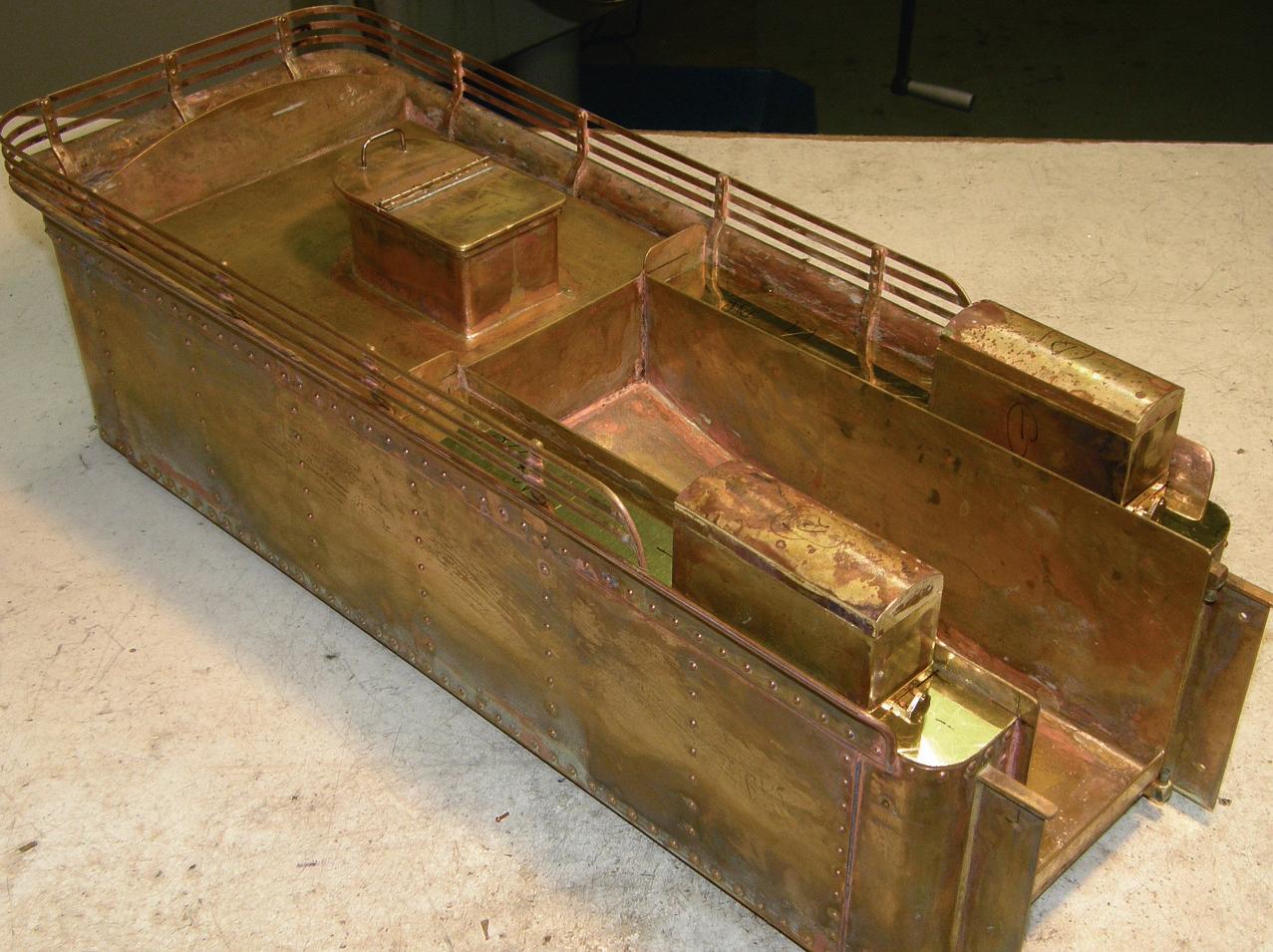
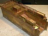
Atendertankfor Cornwall, afive-inch gaugeLNWR2-2-2 locomotive (photo by JimClark).

www.model-engineer.co.uk 3
29 INDEXTOVOLUME232
Vol.
233 No.4745 14 –27June 2024
...
This issuewas publishedonJune14, 2024 Thenextwill be on sale on June 28, 2024. Flywheel for el fo atwin mpound winding engine. Working lamps forafi inch fiv loco o Avisit to aclub lub by the Oxford canal. High-pressure engine by Trevithick ithick Tender body for Cornwall EXPERIMENTAL ENGINE AT COALBROOKDALE THEORIGINALMAGAZINEFOR MODELENGINEERS ng SUBSCRIBE&SAVEUP TO49% Seepage6 fordetails www.model-engineer.co.uk 43 14




























PR INT ONLY


Quar terly direc tdebit for £19
1year direc tdebit for £68
1year credit/debit card for £74


Quar terly direc tdebit for £22*
1year direct debit for £85*
1year credit/debit card for £88*
to




1year direc tdebit for £50*
1year credit/debit card for £54*
*Any digital subscription package includes access to theonlinearchive.
>> Free UK deliver ytoyourdoor or instantdownload to your digital device
>> Save moneyonshop prices >> Nevermiss an issue
>> Receiveyourissue before it goesonsale in the shop
Enjoy12monthsfor just £68 SUBSCRIBE ANDSAVE
Greatreasons
subscribe PR INT +D IGITAL DIGITAL ONLY
classicmagazines.co.uk/ MEDPS 01507 529529 and quote MEDPS Lines areopen from 8.30am-5pm weekdays GMT Ofer ends De cemb er 31,2024. Subscriptionswills tart with thenex tavailab le issue. Dire ct De bitp ay ment swillcontinueonthe agre ed plan unless youtellusother wise Tov iewthe privac yp olic yfor MMGLtd (pub lisher of Mo de lEngineer),p leasev isit www.mor tons .co.uk /privacy Ple asev is it www.c lass ic maga zi ne s.co.u k/te rm sfor fu ll te rm s& cond it ions .


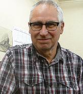



MARTIN
EVANS Editor
DIANE
CARNEY Assistant Editor
Mar tin Evans can be contacted on the mobile number or email belowand would be delighted to receive your contributions, in the form of items of correspondence, comment or ar ticles. 07710-192953 MEeditor@mortons.co.uk
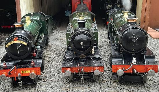
all Newbury right we have 6868 Penrhos Grange John Painter and 1028
GWRlocomotives,all built by Tony Newbury. From left to rightwehave6868 hosGrange,belonging to Stuart Duncan,4202 aGWR 2-8-0T,belonging to JohnPainter and1028 County of Warwick,belonging to PeterLawson.
ParklandsWeekEnds
Writingthisona Bank Holiday Monday,I have just returned from theParklands Holiday Centre in Hemsby,Norfolk, venueofthe verypopular ‘Parklands Week’, held every year at the7¼inchgauge railway whichisa featureof thecentre. Sadly, this year’s ‘Week’was thelastand,later in theyear, therailway will be retiredand thetrack will be gone,toallowredevelopment of thesite.
Theconstructionofthe railway wasbegun by thelate DonWitheridge, proprietor of

Pet,a 7¼ inch gaugemodel of oneof theseven shunting enginesbuilt forthe 18 inch gaugesystematCrewe works, builtin1865. This engine wasbuilt by Eric Upchurch from measurements of thepreserved locomotive.Bravery (or folly)isa necessaryprerequisitefor riding on this engine!
theholiday centre,in1973 with theconstructionofa single ‘out andback’ line. This wasdeveloped over the following severalyears into the approximatelyone mile long railway that nowoccupies the site.Tha annual ‘Parklands Week’began in 1980and hasbeen repeated everyyear except in 2020, when it was cancelledbecause of the COVIDpandemic.
The‘Parkland Week’plays host to awidevariety of 7¼ inch gaugelocomotives,from alloverthe country, andhereI have included a‘picturegallery’ of some of thelocomotives seen therethisyear.
If youare aclubaimingto constructa 7¼ inch gauge railway,you maybeableto acquirethe necessary material from theParklands Railway Thereiswellovera mile of aluminiumtrack,mostlyof 32mm section, on plastic sleepersaswellasseveral otheritems includingrolling
stockand signallingequipment Anyenquiries should be made to BrianBaker at leighsteamer@btinternet.com
It wasa Bank Holiday so did it rain?Yes,ofcourseitdid.

Cock-upCorner
Welcometoour nowregular feature! This time Ihaveto apologisefor an errorinJohn Arrowsmith’s report on the Llanelli Rally (issueM.E.4743, 17th May) in whichI claimed that Llanelli wasinNorth Wales. Of course it isn’t– it’s in SouthWales,asI should well know,being Welshmyself. All thesame, Iblame Wales, which hasfar toomanyplaceswhose namesbegin with ‘Llan…’.
very
ModelEngineer 14 June 2024
8
ee
A
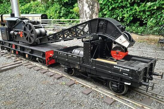
fineLNER25ton breakdowncrane built by DonKetleyand nowowned by John Dalton
BrianBaker
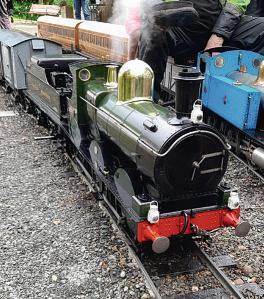
AnicelookingGWR Dean Goods, built by KeithWilson andbelonging to James Duncan,havingpreviouslybelongedto TedMartin.
Three GWR locomotives,
An Engineer’s Day Out
Whitc hurch Silk Mi ll, Mill, Ham p sh ire Hamp

Roger Backhouse visits aRegency mill still weavingsilk on Victorian looms.


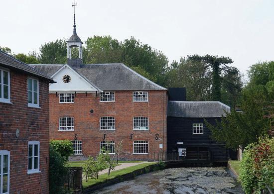
WhitchurchSilk Mill on Hampshire’s RiverTestisone of themostattractively sited buildings visitedinthisseries. It’s an exampleofa small, ruralenterprisethatadapted to developing opportunities with national andinternational associations.Now it is thelast remainingRegency eramill in theUnitedKingdom that still produces silk in theoriginal buildingonVictorian looms (photo1).
It contrastswiththe more industrial Paradise Mill in Macclesfeld (ModelEngineer 4601,7 December 2018) wheresteam powerhad been adopted, although still to be seen thereare hand powered Jacquard loomsthatalso produced complexpatterns andevenpictures. Unlike most Macclesfeld mills,Whitchurch silk mill didonlyplain weaving andthere were no Jacquard looms.
Waterpower wasusedin Hampshirefromearly times. The1086DomesdayBook lists over 300watermills in the county.These were corn mills, of whichmanysurvive such as City Mill at Winchester.Water poweredtextile production is more associated with thenorthwest of Britainand Wales. Rock Mill in Carmarthenshire andQuarry Bank Mill at Styal, Cheshire,survive as water poweredtextile mills
Anotherindustrytouse thelocal watersupplywas at Portal’s Mill at Overtonwhere
paperfor bank noteswas made but, sadly, closurewas announcedin2022 andthe machinerywas recently offered forsale.
Silk industry history
Thesilk worm is native to Chinaand wassmuggled out, frst to theArabworld andthen, particularly,toItaly wheresilk production developedfrom thelate9th Centuryonwards Earlyattempts to startan Englishsilk industry were unsuccessful untilHuguenot (Protestant) silk weaversleft France afterthe Revocation of theEdict of Nantes in 1685, an actofreligious intolerance that caused economic chaos. Many skilledworkers came to England, oftensettling around SpitalfeldsinEast London,which became a centre forhandsilk weaving.
Weaversalsomoved out to Braintreeand Sudburyin Essexand Suffolk.One was Samuel Courtauldwho built up alarge silk business before diversifying into othertextiles. Thesilk worm moth feeds on whitemulberrytrees only anddoesnot generally do well in theUKclimate.A silk worm chrysalis is surrounded by alongflament of thread removedbyimmersingthe chrysalis in hotwater.Silk has atriangularstructure which acts as aprism,thereby giving it anatural shimmer. It is alight andversatile fbre
Englishproducedraw silk wasnot agreat success, though asilk farm operated from the1930sto2011at Lullingstone in Kent.Raw silk is nowimported. Many processesinsilk weavingare similartothose
9 www.model-engineer.co.uk >>
Whitchurch silk mill on theRiver Test is an attractive buildinginthispleasant smalltown.
Whitchurch Silk Mill
Watercress Line
Museum of Army Flying Winchester City Mill TwyfordWaterworks
Milestones Museum
1
involved in making other textilesbut theterminology is different.The hank or skeinin cottonmanufacture is termed aslip in silk weaving. Acotton weavingpirn, holdingthe thread in theshuttle, is known as thequill amongsilk weavers, anda healdorheddlelifting warp threadsalternately in the weavingprocess is knownas theleash
Whitchurch silk mill
Themilloriginatedasa developmentbylocal men, Williamand HenryHayter around 1813 when they setup amanufactory with afoundry andjoinery worksonthe site Thebusinesswentbankrupt andthe site wassoldtoWilliam Maddick,a London basedsilk weaver whoalready hada Macclesfeld silk factory. He commenced majoralterations; insertinga thirdfoor,bricking up centraldoorways,adding more windowsand improving thewater supply. Though Maddick retained ownershiphe mayneverhavevisited themill anditappearstohaveoperated underlocal tenants, knownto have produced silk from 1820. In 1844 themill passedinto theownership of John Spencer andAlexander Bannerman from Manchester buta year laterWilliam Chappell took over,the frst time aWhitchurch manhad been theowner.The following yearswerediffcult forthe silk industry.Food prices were high andworker discontent wasgrowing
2
Therewerechallenges from imported silksand tariff changesput home grown manufactureata disadvantage Thefrstfreetrade agreement between Britainand France in 1860 fooded themarket with cheaperFrenchsilksand many silk mills closed,though theBritish cottonindustry benefted
This wasa direct result of the‘Manchester School’offree trade, oneofwhose apostles wasRichard Cobden,himself a cottonmanufacturer. He wrote, ‘Let thesilk tradeperishand go to thecountries to whichit properly belongs.’(King Cotton itself wastodisappear later. Similararguments were used, in the1970s and1980s when thecottonindustryand ready to wear clothing tradewere beingdestroyed by overseas competition.)
Like most mills,Whitchurch employed childlabour, some coming from parishes eager to fndplacesfor orphan childrenintheir care.Thanksto research by JacquelineBrown andothers, much information aboutthe workforcehas come to light. Workingconditions were poor butprobablyno worsethanother mils of the same period
AWhitchurchshopkeeper, John Hide,boughtthe mill at auctionin1886. Theauction advert mentionedthat‘frst classtrout fshing’was also available. Hisson,James devotedhis workinglifeto themill. He introduced power

3

4
5
loomsmadebySmith Brothers andHattersley, some of whichsurvive today. Themill specialised in weavingsilk serge, much used forlining men’scoats including, from around 1900,those made by Burberry.Thisproduct largely replaced thepreviousthread production
Themill’swaterwheel is likeothersonriverswitha
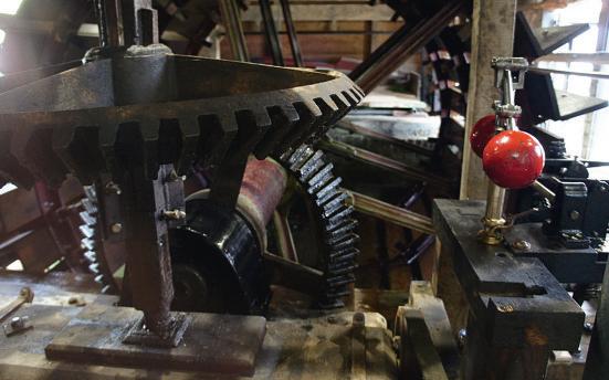
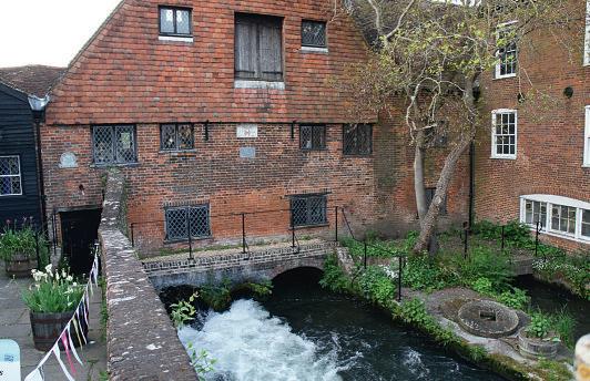
comparativelylow head of water; awide, breast-shottype. It wasreplacedaround1890 by onelocally produced by ArnfeldofRingwoodwitha cast iron frameand elmfoats (photo2).
Laterownersincluded StephenWalters andCo.,based in Sudbury, Suffolk,who ran it forffteen yearsfrom1956
Besidesthe Burberry cloths
10 ModelEngineer 14 June 2024
Awaterwheel drives thesilk mill Widerwheelslikethisare used on ast owing riverswitha relatively lowheado water Wooden oatsneed to be renewedabout everyten years.
Thesilkmill seen from downstream with theRiver Test to theright
Gear wheelsand governor near thewaterwheel.Drive to themachineswas via overheadlineshafts.
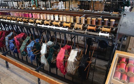
Dyed hanks(slips) of silk areshown here on ‘swifts’below readyfor windingonto bobbins in awinding frame.
they made Ottomansilks, a heavyweave,for theacademic andlegal outftters,Ede and Ravenscroft. Eventually,in 1971, that frmboughtthe mill andsilk production remained thesame, continuing to be used forlegal andacademic gowns. (Whena barrister becomesa King’s Counselhe or she‘takessilk’and wears themoreexpensive cloth.)
By themid 1980s themill waslosingmoney andthe owners obtained planning permission to puthouseson thefront lawn.Thisthreatto an attractive building(photo3) in theheart of Whitchurch roused localpeople- including former Master of theRolls, Lord Denning -who worked with HampshireBuildings Preservation Trusttoraise fundstobuy themill.They were successful butitrequired extensiverebuildingand conservation workswhich were carriedout by Whitchurch
craftsmen. It opened to visitors in 1990 (photo4).
Silk processing
In most instancesofthe processing of naturalfbres, anumberofshort threads have to be combined together andtwisted to form asuitable thread forweaving.Silk is different.Itcomes as very fneflamentsfromthe silk worm chrysalis (orcocoon). Filamentsare between 500 and1500metresinlengthand traditionally came as hanks (slips) whichwereuntangled with aparter.
Silk is usually dyed before otherprocessing.Dyeingwas once done at themillbut dyed silk is nowboughtin.
Slipsare transferredto ‘swifts’ on awinding frame (photo5)and pass through ceramicguideswhich move from side to side ensuring that thesilk is woundevenly on abobbin(photo6). Whilst

8
sitting.Thisisa slow andcomplex process.
themill retainsthishundredyear-old equipment, whichis sometimesused, most silk now comesoncones to be rewound on bobbins
Afterwinding on to bobbins comesthe preparationofthe weaver’s beam.Thisholds the warp threads- i.e. thosethat runlengthwisealong thebolt of cloth. Warping(or beaming) is atime-consumingprocess. In it threadsare arranged in thewarppattern orderasina stripedfabric.
9
Theweaver’sbeamisplaced in aloom andthe threads 7 6
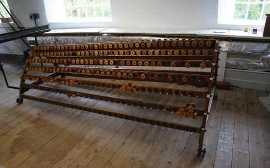
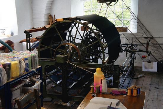
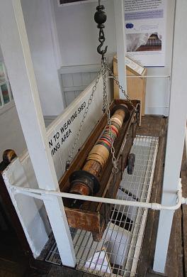
Bobbins arearranged on aframe (photo7). Threads arethentaken across to thebeamer(photo8)tobe arranged on theweaver’s beam.Oncethreads arewound on thebeamistaken carefully downstairs to theweaving foor andthe looms. Formerly alift wasused(photo9).
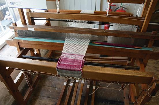
drawnforward as thewarp. Thereare severallooms in the mill, includinga wooden hand loom used fordemonstrations (photo10). As with other looms, thehealds(leashes) 10
11 DAYO UT www.model-engineer.co.uk >>
Lift formerly used to lowera weaver’s beam in acradletothe weaving oor below
Silk passesthrough ceramicguideswhich move from side to side,thusputting threadsonthe bobbinevenly.
Bobbinframe holdsthe hundreds of bobbins that maybeneeded to setupthe warpthreads
Simple hand loom set-up fordemonstrations. Thewooden pedals belowlinkto leverstoliftthe healds (leashes)and create the‘shed’through whichthe shuttle passes.
From thebobbinframe threadsgotothe beamer whichwinds thread on the weaver’s beam.Thatbeamisout of sighttothe left just belowwhere theweaveris
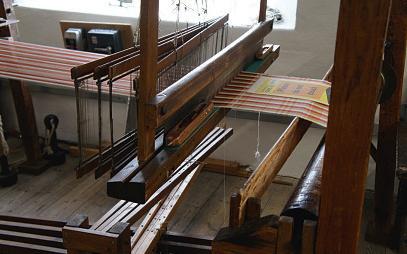
Healds (leashes)are wooden frames holdingeyeswhich each have awarpthread. As aleash liftsitraisesthe appropriate warpthreadtocreatethe ‘shed’ forthe shuttle.


Heald(leash) lifting mechanism. Although themill hasno Jacquard loomsthatcan weavefancy patterns, this device canalter theway healds areliftedtohelpcreatepatterns usinga Dobby mechanism.
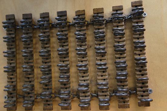
Chaintooperate theDobby mechanism. Even simple wordscould be wovenusing a Dobby butthere’s no evidence this waseverdoneatWhitchurch.
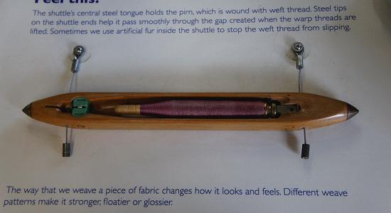
pirn (quill) of thread whichispaidout as theshuttlepasses across theloom though theshed ometimesartificial urisusedinthe shuttleto stop thread paying outtoo quickly.
underthe second andthen over thenextthree.
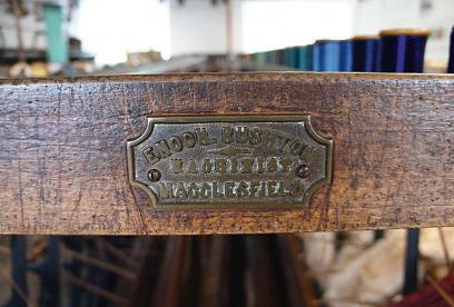
Othereffectsare creating shot silk whichiswoven from weft andwarpthreads of two or more colourstogethergiving an iridescent appearance. Most weavingwas done on powerlooms. Thesewere made at Macclesfeld,a major centre forsilk production (photo12). Once theweaver’s beam wasinplace andshuttles ready, weavingcould beginand leashesliftedautomatically accordingtothe pattern of clothbeing woven(photo13).
Although themill wasnever used to weavethe fancy patternsand pictures possible with Jacquard looms, some patternscould be wovenusing Dobby mechanisms.They arecontrolledbya chainof bars,eachone fttedtolifta particular heald(leash) thus creating apattern (photos 14 and 15).
liftalternately to form a‘shed’ throughwhich ashuttlepasses (photo11). Healds (leashes) carry threadswitheyesthrough whichthe warp thread passes. Oneofthe delightsof silk weavingisthe way different colour effectscan be produced by changing the orderinwhich leasheslift. For examplea twill hasdiagonal lines across thefabric. A so called⅓ twill is made by passing theshuttleunder the frst warp thread andthenover thenextthree. Forthe second pass it goes over thefrst,
Shuttles were similarto thoseusedincottonweaving They were precisionmadewith apirn(or quill) inside holding thethread(photo16). As weavingusedlotsofthread, pirn windingwas automated andwinding machines were a standard ftting in anyweaving mill (photo17). As theshuttle passesthrough theshedto form theweave,a metalbeater comesupbehindtopress the just woventhreads together thus consolidatingthe fnished cloth.
Overview
Themill is somethingunique. Therehavebeen signifcant

12 ModelEngineer 14 June 2024
Ashuttlecontainsa
EnochRustonmaker s lateonthe acclesfield made loom
A loom setuptoweave stripedcloth
Shuttles used lots of thread so pirn (quill) winderslikethese mechanised the windingprocess
11 12 13
16 17
14 15
commissionsfor theNational Trust, Winchester Cathedral andfor many flmand TV productionsincluding Titanic, Senseand Sensibility and Garrow’sLaw, branchingout beyond theOttomansilksinto colourfulfabrics of atypethat couldhavebeen made in the 19th Century. Themill hasalso
Visiting the mill
Whitchurch Silk Mill
28 Winchester Street, Whitchurch RG28 7AL
Tel. 01256 892065
produced silk ribbons, usually made as awidecloth whichis then cutintoindividualribbons Weavershereare able to producespecial commissions andcan make shorterrunsof specialistsilkpatterns. What visitors seeatthe mill dependsonthe processes ongoingatthe time.Duringmy
W: www.whitchurchsilkmill.org.uk.
Parking and Whitchurch railway station arenearby. (Trains, London to Basingstoke/ Salisbury/ Exeter.)
Open Tuesday to Sunday 10.30 -5pm (last admission 4pm). Also open Bank Holiday Mondays.
Further reading
Winders, piecers, warpers and weavers. The story of Whitchurch silk mill,Jacqueline Browne. No bibliographic details. Obtainable from the mill.
Who stole the secret to the industrialrevolution? Glynis Cooper, Pen and Sword 2023.
Early days of silk production in England, including the suggestion that technology was stolen from Italy.
Otherplaces of engineering interest in thearea
WinchesterCity Mill (National Trust -free entry –photo 18)
Remains of acornmill, formerly used as aYouth Hostel.Built 1744 on amuch earliermill site. Partially restored in 2004 but then damaged by floods. Model of cornmilling by water power. Bridge Street, Winchester SO23 9BH
Tel. 01962 870057
W: www.nationaltrust.org.uk/visit/hampshire/winchester-city-mill
The Watercress Line (Alton to Alresford –photo 19)
Ex-Southern Railway line with steam services and specialevents. The Railway Station
resently unctioning dueto ood damage but models show theworking
visitin2023 theweaverwas preparinga weaver’s beam andthere wasnoweaving goingon. On otherdaysthere mightbesomething else happening.However,the mill remainsanattractive spot to visitwithenthusiasticstaff and volunteers.
Guided toursare
recommended wherepossible as theseexplain more butlone visitors will still fndmuchto enjoy. Thereisa café andsmall shop.Besides thecharms of theTestValleythere are severalother places to visit nearby,proof that even in the most scenic areasengineering interest is rarely faraway.
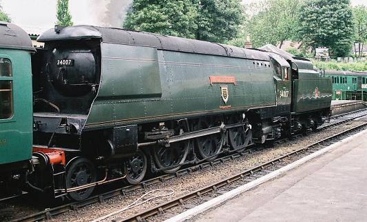
West ountry acific Wadebridge at Alres ordduringa driver e erience day on theWatercressLine hotogra hed thJuly2
Alresford, Hampshire SO24 9JG
Tel. 01962 733810
W: www.watercressline.co.uk
Twyford Waterworks
Edwardian water works with original boilers, Hathorn Davey triple expansion engine, water softening plant and2foot gauge railway. Open 11.00am -4.00pmonselected days.
Twyford Waterworks Trust Hazeley Road, Twyford SO21 1QA
Tel. 01962 714716
W: www.twyfordwaterworks.co.uk
Museum of Army Flying
Well displayed history of army flying from balloons and man carrying kites to helicopters.
Middle Wallop
Stockbridge Hants SO20 8FB
Tel 01264 781086
W: www.armyflying.com
Milestones
Large museum including displays about Hampshire engineering firms such as Tasker, Wallis and Steevens andThorneycroft. All under cover.
Basingstoke Leisure Park Churchill Way West Basingstoke
RG22 6PG
Tel. 01256 639550
W: www.milestonesmuseum.org.uk
13 DAYO UT www.model-engineer.co.uk
City Mill Winchester wasone of many mills on theRiver Test;now ownedbythe National rust achineryisnot
ME 18 19
Miniature Gas Tu rb ines
–A nI ntr odu ction ntrod uct ion

TimColes takesus throughthe basics of modelturbines.
Turbinewheel
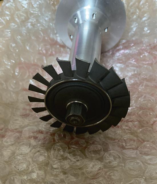
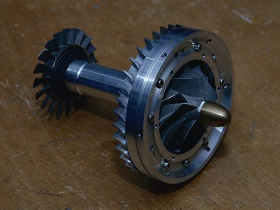
Most miniaturegas turbines useana ial fowturbine wheel (photo8 and this is universally produced as alostwa casting in nconelalloy, to resist the heat andcentrifugal loadson theturbine blades.Thatsaid, some real enthusiastsstill likethe challengeofmaking theirown turbinewheelsby hand.The cast wheelsusually incorporatea ‘sacrifcialring’ in thehub,thisbeing ground away as needed during thebalancing process. Thesacrifcialringis non structural andtherefore partsofitcan be safely removedduringbalancing withoutcompromisingthe structural integrityofthe wheel learly, theturbine wheel,the robust shaftconnectingthe turbinetothe compressor,
andthe compressorwheel assembly need to be balanced to within uiteclose limits if thebearingsare to last fora reasonable time.With theengineatfullpower,the e haustgassesleave the engine at around 600degrees at avelocityofabout 00 metres persecond.
Asmall number of miniature gasturbinesuse aradialinfow turbine, usually sourcedfrom automotive turbochargers, whichall useradialinfow turbines.The main advantage here is that such turbines are readily available, with alesser advantageofusing asimpler Varrangement. These wheelsare,however, uite heavy, although weight savings canbemadeinthe Vdesign andconstruction. They canbe
PA RT 2
alittlelesseffcientthana ial turbines but, correctly set up, radial infowturbineshavea wideroperating envelope and aregenerally more effcient than thee uivalentcapacity a ialturbine in this si e range, whichiswhy allturbochargers, at this si e,use radial infow turbines.See thenoteabout the T Aengines at theend of this article.
Bearings
Thebearingsusedinthese engineshavea toughlifeas they spin at very high speed just howfastdepends on the si e of theengine(photo . Thelargermodel engines runataround100,000 rpm, butthe smallest runuptoan ama ing 50,000 rpm, over ,000revolutions persecond
Thefront bearingrunsina relatively cool environment butthe rear bearingisright up closetothe hottest parts, the Vand turbinewheel.Most enginesnow usecageless, ceramicballbearingswhich seem to performbestinthis application, with bearinglife somethinginthe region of 50 hoursrunning time
Thelubrication system mostly used forthese high speed bearings sounds abit hit and miss, butworks well. Alittlelikea two stroke petrol engine,typically threetofve percentoflubricating oilis mi edwiththe fuel,and asmall proportion of this fuel lubemi is then fedtothe frontbearing from themainfuelline, viaa fowrestrictorfromthe fuel pump.Whenthe mi hitsthe high speed shaftand bearing, it atomises andthenpasses, as afne oily mist,downthe shaft tunneltothe rear bearing, after whichitburns off, as it passes outthrough theturbine
14 ModelEngineer 14 June 2024
A ial ow turbinewheel
8
Thecontrol of gas turbines
As in full si e,the powerofthe engine is governed by therate at whichfuelispumpedinto thecombustionchamber.A gasturbine is auto governing, basedonthe amount of fuel supplied. As thepumpspeeds up,the fame becomesrich anddevelopsmoreheatin thecombustor,e panding the airand making theturbine spin faster.Thiscausesthe compressortodrawinmoreair untilthe fuel air ratiomatches andthe engine settles to the higher rpmwhere thefuel airmi is stable. onversely, as thefuelpumpslows down, thefamebecomes leaner anddevelopslessheatinthe combustorand thereforea lowere pansion of theair in thechamber thisthencauses theturbine to slow down,which
resultsinlessair beinginduced by thecompressoruntil the fuel air ratiomatches andthe engine settles to the lowerrpm wherethe fuel air mi isagain stable. f, on theother hand, fuel is pumped in too uickly, then thecompressorwill not catchup uickly enough and thefamewillbecomesorich that it will e tinguish through lack of o ygen. onversely, if thepumpisslowedtoo uickly, then therewill be toomuchair andnot enough fuel andagain thefamewille tinguishdue to beingtoo lean ami
n earlymanually operated enginesthiswas overcome by windingthe pump rate up anddownslowly, so that the rotorsimplyresponded to theheatdelivered.Modern enginesuse an ECU(engine controlunit or more properly, a A E ( ullAuthority igital

Engine ontrol .Thisclever device is fedwithdataon thespeed of therotor,the e haustgas temperatureand thethrottlesetting,computing thesesignals to controlthe fuel pump speed,toensure theenginereaches thepower setting demanded by thepilot in theshortestbut safest duration.The pilothas asimple powerlever on thetransmitter. However uickly thepower leverismoved by thepilot, the engine only responds as fast as the A E will allow.
Apartfromcontrolling therunning of theengine (photo10 , the A E also automatically controls the startupse uence, as well as theshutdownand cooling se uence.Mostmanufacturers supplya remote display unit whichmonitorsthe performanceand condition of theengineinoperation, this beingdisconnected from theaircraftbeforetake off, although more recent A E Smartdisplaysare designed to remain connected at all times, recordingfight data as abonus.All of this electronic wi ardry makesoperating a gasturbine in aradio-controlled modelaircraftpretty simple n many cases, to start theengine, thethrottletrim is movedfromminimum to ma imumwhich hasthe effect of enablingthe startse uence. Thethrottlestick is then moved from minimumtoma imum andthenbacktominimum, whichthenbeginsthe actual startse uence, controlled automatically by the A E andremaining underthe controlofthe A E until the engine is running at idle speed, at whichpoint authorityisgiven to thepilottouse thethrottle controltoalter theengine powersetting as desired.
Afterlanding,the pilotwill command the A E to shut theenginedown, probably by moving thethrottletrim from ma imumtominimum Thefuelsupplytothe engine will then be stoppedand the engine will spool down to ero,atwhich pointthe A E will starta coolingse uence, drawingair throughthe
engine to cool it down from its operatingtemperature.This ensuresgood bearinglifeby preventing heat soak from ‘cooking’ thebearings. nce theenginereaches itspreset stop temperaturethe A E will deactivate
Thecombustionchamber in agas turbineislikea primus stoveand re uires pre heating to vapourisethe kerosene fuel so that it will burn. Early miniaturegas turbines had gasstart,withpropane used to pre heat thecombustion chamber, this beingignited by astandardmodel glo plug
However, most enginesnow feature‘kero start’ in whicha smallelectricalheaterburns a supplyofkerosenetopre heat thechamber.The earliest enginesalsousedcompressed airtoblowthe rotorround on starting,but nowanelectric motorspins up therotor,under thecommand of the A E . Turboshaft engines
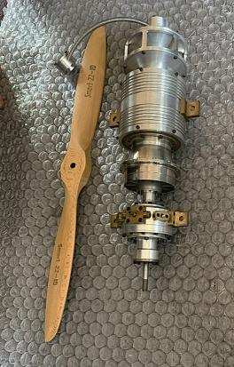
As mentioned, gasturbines canbeusedtoproduce shaft powerbyadding afurther turbinestage. nminiature jets, this consists of anotherlarger powerturbine,known as afree turbine, mounteddownstream of theprimary turbine, and runningonits ownshaft.This then deliversshaft powertoa gearbo , drivingthe rotors of ahelicopterorthe propellerof an aircraft (photo11 . Acast stainlesssteel duct,withan e pandingcross section, takes thefastgases coming offthe 9 10 11
15 TURBINE S www.model-engineer.co.uk >> odelaircra
tturbo ro system
ha t attached to turbinewheel andcom ressor
odel turbinecontrol system
primaryturbine ande pands them before deliveringtothe powerturbine,thisusually beinga lost wa nconel casting. Afterpassing through thepower turbine, thee haust gassesare ledawaybya large cross sectionduct, oftensplit in twotopasseithersideofan aircraft,for e ample.
Thegearbo es areusually uitesimpleaffairswithspur gearsbut they do have forced lubrication, directed into the mesh of thegears.Helicopters arenow regularlypowered by turboshaft engines, and some turbopropaircraftare nowseen at shows, butthe turboshaft is an e pensivebit of kittoput on thefront of a modelaeroplane
Some statistics
As an e ample, forthe purposes of this article, ’m goingtouse theWrenMW5 engine,a well knowndesign originally producingten pounds of thrust butinlater models developedtoproduce nearly twicethatfgure.The

combustion chamberonthis engine is ratedat18kW. This is e uivalent in mechanical termstoabout 5 H . f this fgure, some 18 H is delivered to thecompressor, running at 160,000rpm that’s ,700revolutions asecond. At full power, theengine pulls in around 150litresof airper second,e uivalentto an averagedustbin full. The engine will runwithane haust gastemperature of up to 700 degrees Centigrade butitis bettertokeep down to around 600degrees. uelconsumption is,not surprisingly,highat about 5 ml perminute on full powerbut,whenset againstthe powerproduced, theconsumption is not unreasonable
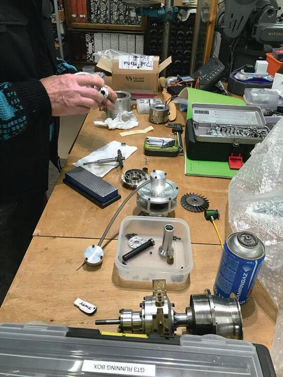
andbuy oneofthese.They come complete with allthe ancillaries such as a A E , fuel pump,fuelvalves, starter anda digitaldisplay.However, some individualsmay want to build theirown engine,perhaps partly to save moneyand partly as achallenge. This is where the T Acomes in (photo12 . nitially establishedin1995 by TomWilkinson, the T A startedout as acontact group to linkjet home buildersto shareinformation on designs, construction methodsand materials.
onstructing amodel turbine as urbine uilders Association
TheGas TurbineBuilders’ Association
Miniaturegas turbines are commercially availablewith thrust rangingfroma couple of pounds throughto50or more pounds andmostfying enthusiastswillsimplygoout
nterest in home building wanedfor atimeas commercialjetsbecame availablebut theorganisation is still thriving to caterfor thosewho still wish to have agoatbuildinga gasturbine themselves,orwho want to gain abetterunderstanding of howtheywork. To make this easier,the T A hasdesigned arange of four engines especially forthe home builder,withoutputs of 15, 0, 5 and 0lbstaticthrust. n each case,the compressor wheel andthe turbinewheel areavailablecommercially from turbocharger suppliers Theturbine wheelsare of the radial infowtype, unlikethe majority of commercialengines
whichhavea ial fowturbine wheels. Theseengines have been designed specifcally for modelengineerstomakein an averagemodel engineering workshop (photo13 . The prototypes have been made usinga standard Myford Super7 lathe. Even themilling operations were undertaken on thelathe with theuse of a vertical slide. Anumberofjigs have been designed to simplify operations,suchasmachining thevanes on thesideofthe diffuser, as well as producing comple profles such as those of theintake.
urtherinformation about the T Acan be foundvia their website www.gtba.co.uk

This articlefrstappeared in the ritish Model lying Associationnewsletter.
16 ModelEngineer 1 une 0
gasturbine oweredlocomotive
12
13
ME
RonFitzgerald takesa look at thehistory and developmentofthe stationary steamengine.
Continuedfromp.692, M.E. 4743, May17
The Stati onar y Th eS tati Steam Engin e
PART 58 –THE COALBROOKDALEENGINE AND THE INTRODUCTION OF THEENGINE TO LONDON
The datesgiven by John Vivian forhis recollections of the StrayParkcombinedcylinder andboilersteam whim engine vary between 1800/1801 and 1801/2.Thiswould suggest that theenginewas built before theTrevithickand Vivian patent wasgranted andasStray Park wasone of themines managedbyAndrewVivianit is reasonable to suggest that he wasproviding afacilityto enable trials to take place. The knownmechanicaldetails of this machineare confnedto Vivian’s statementthatthe cylinderwas containedin theboilerand thepistonrod worked horizontally.Inthe latterrespect it differed from thestationaryenginecontained in thepatentwhich showed the cylinderasvertical.
At aboutthe same time that theStray Park whim engine wasproving itself,another experimental engine wasbeing built by theCoalbrookdale Ironworks. RichardTrevithick’s connectionwithCoalbrookdale wasinitiated by hisfatherwho wasorderingpipes forDolcoath in 1775. Trevithick junior had continuedthe relationship and by thesummerof1802the Dale hadcompleted an engine.Itis possiblethatplans were being prepared in January, three months before thepatentwas sealed (ref305)and theengine wasoperational by 22 August when Trevithick wrotetoGiddy from Coalbrookdale. This letterisworth quotinginits full vernacular:
Shod have writ to yousome time sencebut nothavingmade ufficienttrial of theengine heve referd it untilit in my powertogiveyou an agreeable informationofits progress. heboileri ft iam the Cylinder inche in iam, feet stroake. Thewater piston n.drawing andforcing feet perpendr,e ual beam fir t etitoff with abt lb. on theInchpressure against the team valvewithout it Load before thepumps were readyand have senceworkd it everaltime with pump for theinspectionofthe engineers abtthisnibeourhood.The steam will getupto lb or lb to theinchinabt onehourafter thefire i lighted the engine will etoff when teami abt lb to theinch, abt troke per minute with it load. herebeing agreat deal of friction on uch a mall engine andthe team continue tori ethe wholetime it i worked itgoatfrom lb to lb tothe inch in fair working ... troake prmt it became o unmanageable a thesteam encreasedthatI was obliged to top andput acock in themouth of thedischardging pipe andleveonlya hole open of by of an inch forthe steamtomakeits escape into thewater. he engine will work troake pr mt with a pre ure of lb tothe inch again tthe teamvalve and keep it con tantly wemingwith wt (3 cwt.) of Coal every four hour . havenow a valvemakingtoput on topofthe pump toloadwitha teelyard
so to tryhow many pounds to theinchitwilldoofrealduty when the team on thevalve i lb tothe inch. cannotput many more pumps (lengthenthe standpipehence thehead) as they areverylofty already . he boileri inchthick and think thereisnodangerinputting it much higher (ref306)
Trevithick’s letterdescribes an engine with afourfeet diameter boiler, theshell of whichwas 1½ inches thick (certainly cast rather than wroughtiron) anda cylinderof 7inchesboreby3 feet stroke It hadbeen tested workinga 10 inch diameter pump with abeamconnectionbetween thecylinderand theplunger pump.The waterwas pumped into astand pipe 35½feet high.Steam pressure varied between 50 p.s.i. and145 p.s.i. andthe referencetothe exhaustescapingintothe waterprobablyindicates that afeedwaterheaterwas used similartothatincludedinthe patent
Thereisanother description of what is undoubtedlythe same engine.Simon Goodrich’s Journalrecords in somewhat more elegantprose:
2. Wedne day2 rd ebruary . Coal rook ale. reakfa tedearly andthen went over the alecompanie work along with r. homa . aw r. revithick engine whichworks by theforce of steamwithout condensation t hadworkeda double inch pump feet troke troke perminuteraising thewater
17 www.model-engineer.co.uk >>
feet whichwa uppo ed to con ume cwtofcoal per hour.Thisenginewas erected underthe directionof r. Trevithick foranexperiment. he team cylinderinwhich thesteam wasmadetoact both way wa placedwithina ca t iron boiler, thepi tonrod coming throughthe tuffingbo at thetop-----round thi boiler wasanother case of cast iron at a ufficient di tance from it to allowroom forthe fireplace and ue the firewa made on aplate at thebottomof theouter ca e andcirculating betweenthe outercaseand the boiler, enteredbya hole through onesideofthe outerend a chimneyofbrickwork carried up a ufficient height to produce draught. To preventthe outer case from burningawayor conducting theheatoff toofast it wa lined on thein idewith firebrick .
Much of thecontent of Goodrich’s diaryentry canbe identifedwithTrevithick’s lettertoGiddy butitadds severalsalient points.The cylinderisstatedtobedoubleacting andisinsertedintothe boilervertically.There wasno condenser. Theboilerhad a double shellofcast-iron,the hotgases circulatinginthe spacebetween theshells.The freplace wasunderneaththe innerboilerand,toprevent the casing burningaway, it was lined with frebrick
Athird source of information is to be foundinthe Coalbrookdale Ironworks ettlingJournal - (ref 307)thatrecords chargesto… RichdTrevithick& Co., which maybetaken as referring to thethenpartnersinthe patent, Trevithick,Vivianand West Theheading is sub-titled or Castings forExperiments---now at the ale .The listofitems includes: boilerat cwt 2 tr . lb ca efor do.22cwt. tr 2 lb cost £48. 3. 7d cylindertop andpipe cwt tr. lb and tuffing bo lb chargedat£18.7.8d. otably, thefrsttwo items on thelistspecify a…boiler anda case forthe boiler
This indicatesdoubleshell construction similartothat specifed in thepatentwith an innerwater andsteam vesselenclosedbya cast–iron outercasing. Together these descriptions suggestthatthe Coalbrookdale experimental engine wasvirtually identical to thepatentdrawing of the stationary engine.
Thetotal cost to thepartners was£2055s. 10½dbut therewerefurther charges whichweredebited on the 18th October1802including itting attg. ngineboiler etc.,making oint putting up pipe etc., men in all day at per dayand 2men imilarlyemployedfor day at 2 -per day.
TheCoalbrookdale engine mayalsohaveservedasa demonstrator (Goodrich’s inspection of it wasdoubtless intended to persuade a prospectivecustomer).That ademandexisted fora cheap, compactand fe ibleengineof less than 15 horsepower had alreadybeen demonstrated by thesmaller engines recently produced by Boultonand Watt, Murray. Trevithick’s engine hadthe additional advantages of notrequiring coolingwater forthe condenserand amuch
higher potentialspecifc output duetothe raised steam pressure.All of thesefactors must have been thoughttogive theenginea strong appeal for London with itsmultitude of smalltrades.
Even before thepatentwas appliedfor Trevithick had apparently suppliedanengine to London.Francis Trevithick, baseduponanextract from Trevithick’s accountbook underdate1800, recordsa paymenttoArthurWoolf:
o Arthur Woolfgoing to London a engine fireman with the hellandengineat per year
Thebiographerelaborates lateronthe same page: in ahighpre ure portable teamenginewa wassenttoLondonincharge of Arthur Woolf, thewell-known engineer. (ref309)
In Volume II of the Life this hasbeen expanded into: n Woolf, whohad been aminecarpenter went to London with thefir thigh pressure steamenginewhich Trevithick hadsentbeyondthe limit ofCornwall ---probablyto eu rewery--- , forhewa therein andinthe receipt of a year from revithick a engine fireman. romthe
date of Woolf patentin hispayment from Trevithick cea ed FrancisTrevithick’s footnotes:
n . revithickaccount book ol .p.
n.Capt. John ivian recollection ol. . p. 2. (ref308)
By this time Woolfwas no longer employed at the HayleFoundry.Following the tradeofcarpenter,hemoved from Cornwall to London andafter abrief period with Bramah he appliedhis skills to engineering. This ledtoan involvementwithHornblower andMaberley, buildingtheir patent enginesand it was theinstallation of oneof theseengines that brought himintocontact with Meux’s riffn reweryin ondon. Hornblower’s engine forMeux wasbuilt in 1796and as a result Woolfwas appointedas thebrewery engineer,a post he held from April1797until October1806, initially paid £2 perweek,later raised to £3 per week (ref310).
Thestatement in thesecond volume of the Life seems to be Trevithick’s attempt to reconcile theentry in the accountbook with Woolf’s
18 ModelEngineer 14 June 2024
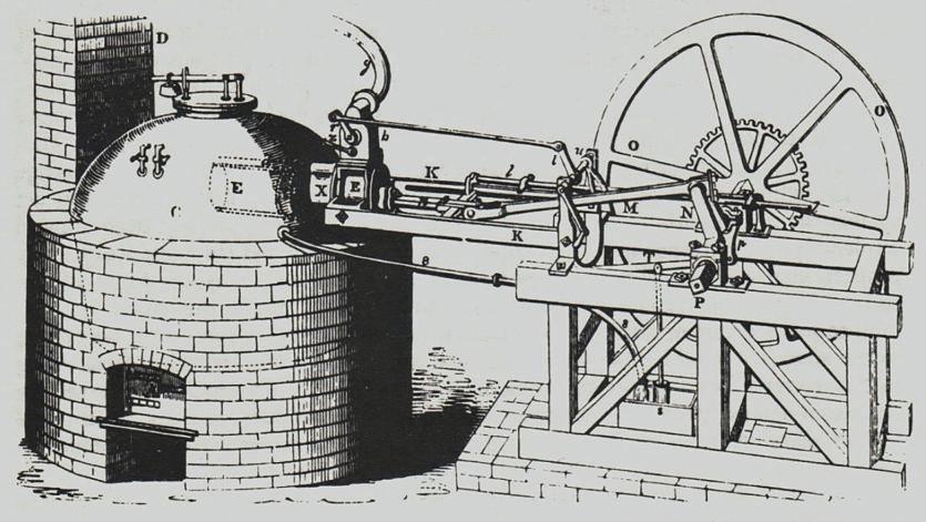
John Farey’s1804 drawingofthe London dyehouse engine
Fig 187

John Farey’s1804 drawingofthe London dyehouse engine cylinder.
employment at Meux’s Brewery butthe suggestionthatthe Trevithick engine wasintended forthiscustomerisconjecture on FrancisTrevithick’spart. Fora number of reasonsthis is diffcult to accept. irstly,if theenginewas intended forthe brewery, thequestionarises whyWoolf,who alreadyhelda responsiblesalariedposition at that establishment, should be paid afurther £2.10. 00.per week by Trevithick to actasa freman Secondly, theaccount book explicitly describes theengineasthe helland engine.Asthe Suffolk place name carriesnoidentifable signifcance, Shelland seems to be apersonalnamebut thereisnoknown connection between such apersonand theMeuxestablishment. Finally in discussing Meux’s Brewery, PeterMathias,in hisauthoritative historyof theeighteenth andearly nineteenth centurybrewing industry ( 311), considers thepossibilitythata Trevithick engine wasinstalledwhilst Woolfwas machinery superintendent butconcludes that this wasconfusion with an engine of Woolf’sown design As furtherevidencehepoints outthatwhenthe brewerywas offeredfor sale in 1809,the
cataloguemakes no reference to aTrevithickengine. Nor does Rhys Jenkinsmention such aTrevithickengineat thebrewery in Woolf’stime ( 31 ).
f Meu ’s riffn rewery is unlikely to have been the location forthisfrstTrevithick high-pressure engine outside Cornwall then it remainsto determinethe relevanceof thenameShelland.Accepting that Shelland’s business was entirely independentofthe brewerythenthe possibility arises that Woolfwas acting forother partieswhilsthewas employed by Messrs. Meux, effectivelyfollowing theroleof consulting engineer.The term freman at that time referred rather to engine manthanitdid to stoker
Within thenexttwelve months John Fareysaw several more Trevithick engines workinginthe metropolis.He made adetaileddrawing of one such machinewhich wasinuse at adyehousein1804(ref313, 1 ).
Although thereare anumber of similarities with thedesign showninthe patent drawing thedifferences arenotable Most obviously, thecylinder hasbeen repositioned from theverticaltothe horizontal
188
( 1 ). This allowedthe somewhat vulnerable framing carryingthe crankshaft, fywheel andthe outerends of theslidebarsshown in thepatenttobereplacedby asturdiertimbertrestle.In both thepatentand in Farey’s engine most of thelength of thecylinderbarrelwas enclosed within theboiler. The valveoperating mechanism is more robust in theLondon engine;a simple reciprocating rodwithtappets tripsthe swinging valverod arm replacingthe delicatecam ring androllerwithits unexplained linkage
REFERENCES
Farey’sdrawing of thevalve chestshows amoreelaborate arrangementcomparedtothe patent design with twoplug cocks, oneabove theother Theuppercockcontrolledthe steamadmission andexhaust, thelower valveacted as astop valveinterceptingthe steam port that ledintothe outerend of thecylinder. Theexhaust from this endofthe cylinder exited througha separate port butinlet andexhaust to andfromthe otherend of the cylinderwas by wayofthe elongatedportthatran down side of thecylinder.
Thecomplex double-skinned boilerofthe patent with its baroquefeet wasabandoned in favour of asimpletun boiler, familiarfromthe earliest days of theNewcomenengine. Entirely made of cast iron,the topwas hemi-spherical butthe sideswerea tapering cylinder, narrowing as it approached thefre setting.The fregrate wasbuilt in to abrickwork cylinderwhich enclosed the cast-ironboilershell. Abovethe fre, thebaseofthe boilerwas domed. Adead-weight lever safety valvewas mountedon amanhole coveratthe highest pointofthe domedtop of the boiler.
To be continued.
NEXT TIME
TheLondonroadcoach
Ref 289 Dynasty of Ironfounders. The Darbys andCoalbrookdale. Arthur Raistrick. Pub Longmans.1953. P. 161
Ref 306 Quoted p. 163, Dynasty of Ironfounders.The Darbys and Coalbrookdale.Arthur Raistrick. Pub Longmans. 1953.
Ref 307 Dynasty of Ironfounders.The Darbys and Coalbrookdale. Arthur Raistrick. Pub. Longmans 1953. Appendix 5
Ref 308 Life Vol II, p. 112
Ref 309 Life..Vol. I. P. 90.
Ref 310
ACornishEngineer: Arthur Woolf,1766 –1837 Rhys Jenkins. T.N.S. Vol. XIII 1932-33. P. 55 et seq.
Ref 311 The Brewing Industry in England 1700-1830.Peter Mathias. Pub. C.U.P.1959 p. 96
Ref 312 ACornishEngineer…. Rhys Jenkins op.cit.
Ref 313 ATreatiseonthe Steam Engine, Historical, Practical and Descriptive (1827).John Farey. VolII. P. 14.
19 THE STEAM ENGINE www.model-engineer.co.uk
Fig
LNER B1 Lo co mo ti ve
PA RT 47 – AW SG EAR AN
DLAM PS

Doug Hewson presents an authentic5 inch gauge versionofThompson’s B1 locomotive.
Continuedfromp.771, M.E.4744, May31
First of all, Iwould just liketotouch on theAWS (Automatic Warning System)gearwhich is quitevisible on lots of later locomotives. It is more or less identicalonmostlocomotives andsadly Ihavenodrawings of thegear. However, Idid take lots of photographsofthe gear on aBlack Five at Llangollen whichwas beingsteamed by thelategreat BobMaxwell. I hada most delightful morning couple of hourschattingto Bobashewanderedround the engine oilingall roundand he gave me free access to take lots of photographs. Theengine was44806 hoto ph 33 is theshoeonthe bottom of theplate whichisbolted to thebackplate to retain thelower linkofthe screw couplingtoprevent it from unscrewing hoto ph 33 is thetop of theplate bolted to thebottomofthe buffer beam. hoto ph 33 is the mounting forthe transponder shoe (ifthatiswhatitiscalled!) andthe bracketrysupporting same.These aremounted on thefront crossmemberofthe bogieand on my 4MTtheyare mountedonthe pony truck. Thetransponder is quiteeasily spotted, like asmall upside-
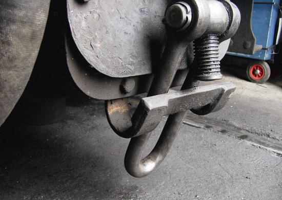
Screwcouplingretaining shoe


down dome hoto ph 3 is acloser-up view of the mounting gear IpromisedthatI wouldcome back laterand describe the lampsonmyengines.One thingI foundmostvaluable -and Iwould notliketobe withoutit- is my gaugeglass lamp. fttedthese on to allon ourlocomotives when Iwas buildingthe railway around my newhouse.Thiswas so that we couldworkintothe nightand we did, sometimesuntil almost midnight.Itislit by a5mm LED when they were anew idea.All
we couldget at that time was red, yellowand green,I think. When thehighbrightnesswhite ones came on themarket, we thoughtthattheywereamazing. However, Ithought that they were abit toobrightfor me,so Istuck with my yellowonesas they look farmorelikeparaffn lamps. Allyou need to make theseisa double AA battery holder whichyou canhide somewhereonyourengine, like inside atool boxorunder the cabfoor,someverythin T E coated wire,some10thou nickel silver sheet,a switch,a
20 ModelEngineer 14 June 2024
Topofthe retainingshoe.
Transpondershoemounting.
337 338 339


