


BassettLowke ‘Eclipse’ engine revisited




❖❖
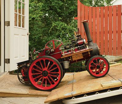
Inaugural trainon Edinburgh’s newtrack Forrester locomotiveon the Dublin railway Threeinch Allchin embarksona day’souting
FO RRE ST ER’S ‘C RE WE TY PE’LOC OM OT IV ES TH EO RI GI NA LM AGAZ IN EF OR MO DE LE NG IN EE RS Vol. 233 No.474628 June 2024 –11July2024 Join ouronlinecommunity www.model-engineer.co.uk
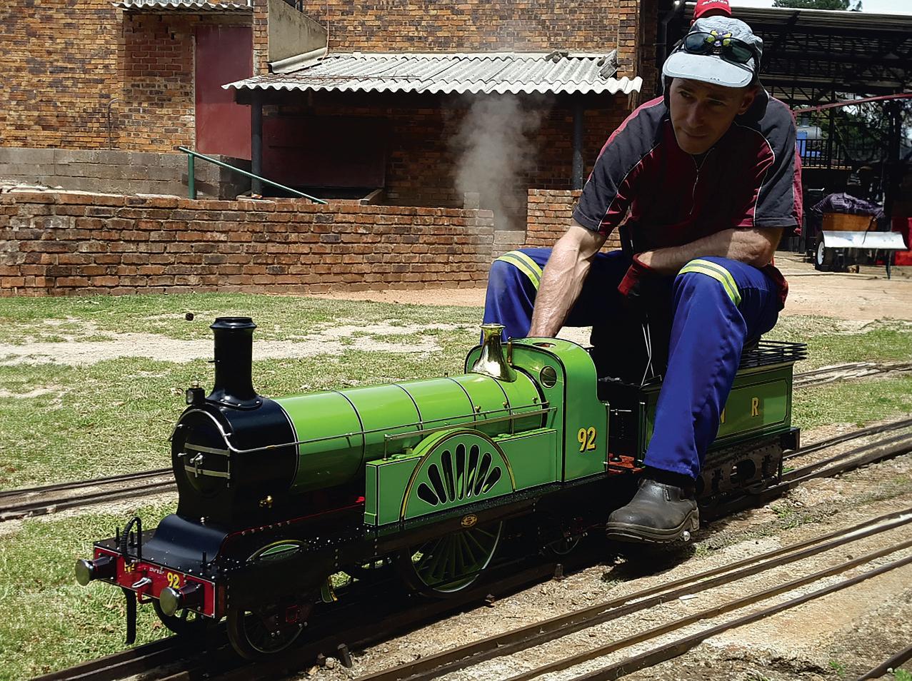
AStirlingSingle in SouthAfrica





PublishedbyMortons MediaGroup Ltd, MediaCentre, Morton Way, Horncastle,Lincs LN96JR
Tel: 01507 529589 Fax: 01507 371066
©2023 MortonsMedia ISSN 0026-7325 www.model-engineer.co.uk
EDITORIAL
Editor: Martin R. Evans
MEeditor@mortons.co.uk
Deputy editor: DianeCarney
Designer: DruckMedia Pvt. Ltd. Club News: GeoffTheasby Illustrator: GrahameChambers Publisher: SteveO’Hara
CUSTOMER SERVICES
GeneralQueries andBackIssues 01507 529529 Monday-Friday: 8.30am-5pm Answerphone24hr help@classicmagazines.co.uk www.classicmagazines.co.uk
ADVERTISING
GROUPHEADOFINVESTMENT– Lifestyle& TractorPublications |www.talk-media.uk MasonPonti mason@talk-media.uk
A: Talk Media, TheGranary,Downs Court, YaldingHill, Yalding, Kent ME18 6AL
Investment Manager: KarenDavies karen@talk-media.uk
PUBLISHING
Salesand distribution manager: Carl Smith
Marketingmanager: Charlotte Park
Commercialdirector: NigelHole
Publishing director: DanSavage
SUBSCRIPTION
Full subscription rates(butsee page 66 foroffer): (12months, 26 issues,inc post andpacking)–UK £132.60. Export ratesare also available, UK subscriptionsare zero-rated forthe purposes of ValueAddedTax Enquiries: subscriptions@mortons.co.uk
PRINTAND DISTRIBUTIONS
Printedby: WilliamGibbons &Son,26Planetary Road,Willenhall, West Midlands,WV133XB
Distribution by: SeymourDistributionLimited, 2EastPoultry Avenue,LondonEC1A9PT
EDITORIALCONTRIBUTION
Accepted photographsand articles will be paid for upon publication. Itemswecannotuse will be returned if accompaniedbya stampedaddressed envelope andrecordeddeliverymustclearly statesoand enclosesufficient postage. In commonwithpractice on otherperiodicals,all material is sent or returned at thecontributor’s ownriskand neitherModel Engineer, theeditor, thestaff norMortons MediaLtd canbe held responsiblefor loss or damage,howsoever caused.The opinions expressedinModel Engineer arenot necessarily thoseofthe editor or staff. This periodical must not, withoutthe writtenconsent of the publishers first beinggiven,belent, sold,hired outor otherwisedisposedofina mutilatedcondition or in otherunauthorisedcover by wayoftrade or annexed to or as part of anypublicationoradvertising,literary or pictorialmannerwhatsoever.


http://www.facebook.com/modelengineersworkshop

http://twitter.com/ modelengineers



68 SMOKERINGS
News,views andcomment on theworld of modelengineering
69 INNOVATIONSINTHE LAST 100 PUBLISHED MODEL ENGINEER ARTICLES
Luker reflects on hiscontributions to Model Engineer
72 ATWINTANDEMCOMPOUND STEAMENGINE
Graeme Quayle presents an interesting design fora compound windingengine.
77 BUTTERSIDE DOWN
SteveGoodbody returnswithfurther tales of thetrials andtribulations of amodel engineer’s life.
82 FLYING SCOTSMAN IN 5INCHGAUGE
PeterSeymour-Howellbuildsa highly detailed A3 locomotive basedonDon Young’s drawings
84 HARRISTWEED
RogerBackhouse discovershow an iconic fabric is produced
87 SMEE NEWS
Martin Kyte reportsfromthe SocietyofModel andExperimentalEngineers.






SUBSCRIBE&SAVEUP TO49% Seepage66 fordetails.


90 SUPERGLUEISSUPER
PatrickHendracontendsthatsuperglue really does liveuptoits name
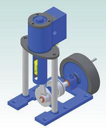
94 BASSETT-LOWKE ECLIPSE REPLICA
JasonBallamyrevisitsa smallboatengine produced by Bassett-Lowke acentury go
98 BOXERS TO POLKAS
RonFitzgerald describesthe work of George Forrester,originatorofthe ‘Crewe Type’ of locomotive
103
THEBALLADOFALMONDELL
Andrew Newton presents thehistory of the Edinburghclub’snew track, accompanied by song
107
LNER B1 LOCOMOTIVE
Doug Hewson presents atruetoscale fiveinch gaugemodel of Thompson’s B1
112
CLUB NEWS
GeoffTheasby compilesthe latest from modelengineering clubsaroundthe world.
115
CLUB DIARY
Future Events.
E CO VER
Luker’s 5inchgauge 2-2-2StirlingSingle locomotive (photo by Mrs Luker).

www.model-engineer.co.uk 63
Vol. 233 No.4746 28 June 2024 –11July 2024
ON
TH
...
This issuewas publishedonJune28, 2024 Thenextwill be on sale on July 12, 2024. BassettLowke ‘Eclipse engine revisited Inaugural train Edinburgh’ newtrack wtrack Forrester Forrest locomotive loc the Dublin railway Threeinch Allchin embarks day’souting souting AStirling Single in South Africa FORRESTER’S ‘CREWE TYPE’LOCOMOTIVES THEORIGINALMAGAZINEFOR MODELENGINEERS uly ng
www.model-engineer.co.uk 103 98








SUBSCRIBE ANDSAVE
Enjoy12monthsfor just £68

PRINT
ONLY


PR
Quar terly direc tdebit for £19
1year direc tdebit for £68
1year credit/debit card for £74

INT +D IGITAL



DIGITAL ONLY
Quar terly direc tdebit for £22*
1year direct debit for £85*
1year credit/debit card for £88*
1year direc tdebit for £50*
1year credit/debit card for £54*

*Any digital subscription package includes access to theonlinearchive.

>> Free UK deliver ytoyourdoor or instantdownload to your digital device
>> Save moneyonshop prices >> Nevermiss an issue
>> Receiveyourissue before it goesonsale in the shop
Greatreasons
to subscribe
classicmagazines.co.uk/ MEDPS 01507 529529 and quote MEDPS Lines areopen from 8.30am-5pm weekdays GMT Ofer ends De cemb er 31,2024. Subscriptionswills tart with thenex tavailab le issue. Dire ct De bitp ay ment swillcontinueonthe agre ed plan unless youtellusother wise To view theprivacy policy forMMG Ltd(publisherofM odel Engine er), please visitw ww.mor tons .co.uk /privacy Ple asev is it www.c lass ic maga zi ne s.co.u k/te rm sfor fu ll te rm s&cond it ions . ( 8

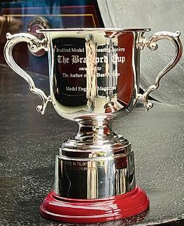


Bradford Cup

 MARTIN EVANS Editor
DIANE CARNEY Assistant Editor
Thevotes areinand have been counted! Many thanks to everyone whotook thetrouble to vote
Iampleased to announce that theclear winner this year is RonFitzgerald forhis excellent series on thestationarysteam engine.The pricelesstrophy will be presentedtoRon in due course –watch this space!
Midlands Show and Competitions
Meridienne Exhibitionslook forwardtowelcoming youto oneofthe UK’s largestmodel engineeringexhibitions,the Midlands ModelEngineering Exhibition,takingplace from Thursday 17th to Sunday 20th October2024.
Therewillbe over 30 clubsand societies present displaying hundreds of exhibits covering awiderange of modellingskills
Therewillalsobe nearly 40 of theleading model engineeringspecialisttrade suppliers,all waitingtomeet youand provideeverything youneed foryourmodelling activities
SMEE will be presenting some practicalworkshops againthisyearwhich will focus

on abeginner’sproject Elmers No 19.Overthe duration of theexhibitionthe team plan to make multiple sets of the partsand build anumber of runningexamplesasthe show progresses. This is the modelinmoredetail: www. journeymans-workshop.uk/ elmer19.php
Forthe more experienced modelengineer therewill also be demonstrations of more complextechniquesaswellas arange of theirfamousmodels on displayand achanceto meet themembers andlearn abouttheir training courses, programme of meetings and membership
The competitionand display entries arenow open,and theentry form canalsobe downloaded from theshow website.
At this year’s exhibition,the John StevensonTrophy will be awardedinassociationwith ModelEngineer’s Workshop andthe ModelEngineer website. This competition is awardedfor excellence in practicaland useful workshop equipment. Formore informationonthe competition andhow to enteryourworksee www.model-engineer.co.uk
The Associationof HelicopterAerosports will be at theexhibitionwithanindoor static display, simulator, and outdoor flyingdemonstrations!
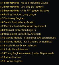
Thestaticdisplay will cover varioustypes andsizes of R/C helicopters andthe simulator will allowvisitorstohavea go at flyingR/C helicopters
Weatherpermittingthe AHA will also have an outdoorflying demonstrationofscale model helicopters.Modelsincludedin theflying demonstrations are a1/8 scaleMH-65 Dauphin, a 1/7scale Bell UH-1BIroquois (Huey) anda 1/8scale Westland Lynx HMAMk8.
The lectureprogram is also shapingupand thefullschedule will be announcedsoon!
This unique exhibition is theresultofa tremendous amount of effort by many hundreds of modellers and otherenthusiasts.A full list of confirmed exhibitors to date is availableatwww. midlandsmodelengineering. co.ukaswellasthe competitionentry form and advancetickets!

Mar tin Evans can be contacted on the mobile number or email belowand would be delighted to receive your contributions, in the form of items of correspondence, comment or ar ticles. 07710-192953 MEeditor@mortons.co.uk



ModelEngineer 28 June 2024
68
Elmers No 19
ModelEngineer
Midlands Show
Inn ov ati ons in the Inno v ations
La s t1 00 Pu bl ished Last 1 0 0Pub lished Model Engineer Eng Ar tic le s

Luker looks back over hisrecently achieved century.
Nonrever ti
Wouldyou believe Ihave recently achieved my century forpublished articles in model engineeringprint (mostof whichwerein ModelEngineer)? Ifelta warm fuzzy feeling when Irealised Ihad hitthis milestone, notonlyfor thegood innings, butmorebecause I managedtokeep most of the articles technicaland novel.
Over theyears Ihave received some greatfeedback butmylastarticle ‘demiseof themodel engineer’seemed to have hita chordwithsome readers. Thearticle dealt mainly with howtopromote the hobby specifically amongst theyouth,but Idobelieve modelengineeringneedsto evolve to caterfor thenext generation with adifferent skill set, includingmodernmaterials
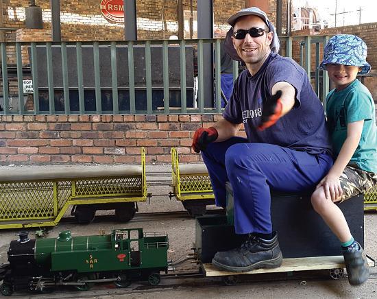
My little William,a 2-6-2T engine designed by Martin Evans. Ibuilt this locomotive very closetodrawing,but foundthatittendedtorun with acolderfre andhad an unevenbeat. Thevalve timing andgrate wasmodifed to bringitinlinewithmy newermethods;now this littlelocomotiveisa pleasure to drive.
andmethods.Innovation is thetechnical evolutionof mechanical systems, and as Istepoverthe 100-ish (sic)article Iwould liketo take alook back at some of my innovative ideashidden amongstthe construction series,orin-betweena broader subject.
Idoneed to be upfront on afew things before I begin. Nothingisreally new; everything hasbeendoneor tried, or is just avariation,or extrapolationofsomeone else’s idea.Withthatinmind theterms innovation or novel areusedveryloosely! Allthe ‘novel ideas’ in this articlehave been used,and tested,inmy builds. Theideas,tothe best of my knowledge, were novel (maybe just to me)orapplied in auniqueway.Whether or not was first is always debatable and, in my experience,there’s always someonethatclaimsto have alreadythought of an idea with very littletoshowfor their visionaryinsight
Modern techniques and calculations forbalancing steamengines
Thefirstinnovation hasnever explicitly been published buthas been lurkinginthe background of my livesteam designs. Thermodynamic balanceoflivesteam models hasalwaysbeen of particular interest to me.Thisisnot to be mistaken forheattransfer, whichisata componentlevel, butwill affect theoverall thermalperformance.For example if theheatflux into theboiler(heat transfer)
doesn’t matchthe cylinder sweptvolume(thermodynamic balance) then youhavean unbalanced steamengine whichwill either sufferfrom asafetyvalve constantly blowingoff or afire that runs cold or burnsout quickerthan it should.MartinEvans,inhis fineboo TheModel Steam Locomotive gave ratios for grateareatoboilertubearea (heatinput)and grateareato cylinderswept volume (steam usage) respectively,which seem to work well forthe more modern locomotives, butfallshort with thevery oldprototypes, whichare my preferredmodels. I’ve found theratio of gratearea/design tractive effort (ref1)togive abetterindicationofsteam usagefor most enginesand Itypically aimfor aratio of between 100and 130mm2/ kg.Thiswas experimentally verifiedwitha number of club locomotivesand seemed to hold true
Once I’mhappy with these ratios,everythingfrompipe sizing,blast nozzleheights and sizesetc.tovalve travel and port sizing is ‘handcalculated’ in an excelspreadsheet and asolverusedtooptimizethe design before anything is modelledorsimulated (photos 1 and 2).
Computer aideddesign (CAD)and virtualdynamic modelchecks
When designingmymodels Ikeepaneye on thecentre of gravityand trytobalance thedesign specifically the weight over thedrive wheels
69 www.model-engineer.co.uk >>
PA RT 1
1

3 2
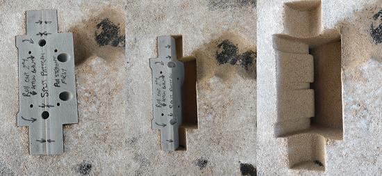
Acomplex cylindercasting whichwould normally requiremultiplesplit lines is cast bysplitting thepattern;thisismucheasierwith3Dprinted patterns. Incidentally the sand is amix of plastersand, bentoniteand four;myhomemademix that seemsto work very well forcopperbased alloys
TheStirling2-2-2 wasdesignedusing theratiosinMartinEvans’s book butI found thethermodynamic balancewas out, causingthe safety valves to constantly blow off. This locomotive wasfttedwithmyfrstexperimentalstainless steel boiler which mayhavecontributed.The imbalancewas easy to fx by adjustingthe grate andblast nozzle; this locomotive runs perfectlynow.
(fg 1). This is done by adding weight to sneaky areas; a good exampleisthe footplate watertankof Ballaarat which wasfilledwithleadtobalance thedesignperfectly.Most 3D models canbeusedto checkfor valveclearance and movement as well as looking forclashes in thevirtual space before cutting anymaterial.
CADinmodel engineeringis notnew andfor themostpart is becoming more common. This is incredibly beneficialto thehobby allowing filesfor lasercutting to speedupbuilds andma ethe final modelmuch easier to assemble
Thedaysofcalculating bendingprofiles arelonggone with thesefancy programs
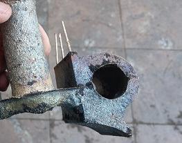
Thecylinderasitcameout of thesand. Note howthe breather holesextendfor almost an inch,indicatingtoo much superheatfor this pour,but therewas very littleburn-on with thehomemade reducing sand mix.
doingthe jobfor thedesigner. With aclickofa fewbuttons complexprofiles canbeturned into aflat pattern a exported,senttoyourfriendly lasercutters andinnotimethe flatprofileisready to be folded
4 5 6
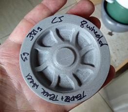
Arelativelysimplepattern,until it needs to be made usingwood. Imaginethe complexity of making thoseribsonthe undersideand blending thecorners without3DprintingorCNC
or bent to aperfect shape.
Thecastcomponent models areveryusefulto calculatethe castingmodulus to determineifthere will be draw inclusions when casting. This is oneofthose things youtry to solvebeforegoing throughthe effort of melting achargeand casting. These models canbescaledwitha simple clickofa buttontotake into accountany shrinkage. Ingates, split lines andrisers canbeincludedwithlittle effort making ramming easier than if this waseyeballedwith akitchen spoon
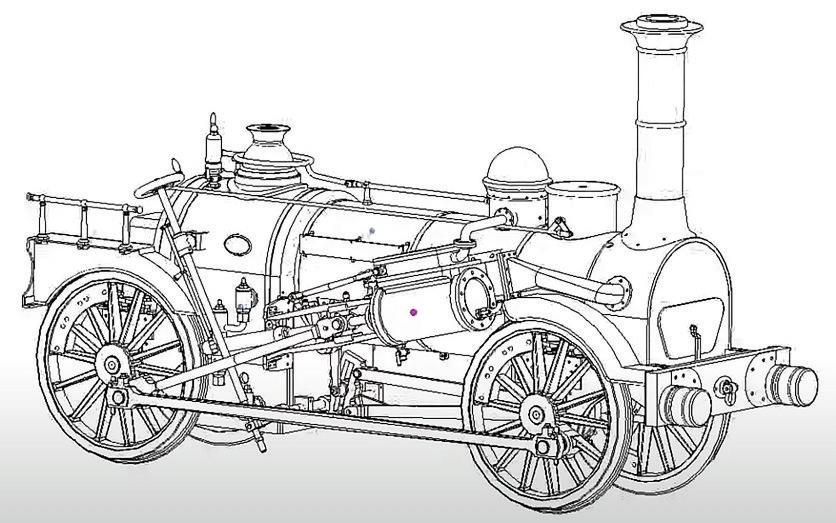
The Fire Queen wasa particularly specialmodel.Itwas very closetoscale andinthe endthe centre of gravitywas almost perfectlycentred between thewheels. Theyoung engineer that designed theoriginalprototype,nodoubt,had this in mind when designinghis fnelocomotive!
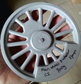
Amainwheel pattern with aribbedrim 3D printing is perfectlysuitedfor all thesefllets andradii.
70 ModelEngineer 28 June 2024
Fig 1
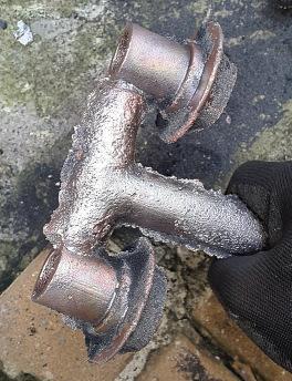
Copperisone of themorediffcult metals to cast becausethe chance of blow holes, duetogas pickup,is very high
3D printing of complex patterns
Most people canvisualise thesymmetrysplit lineand draftanglesrequiredfor removing patterns from sand Recently Icasta cylinder that hadnoconvenientsplit lineand,instead of making a multiple boxmould,I solved theproblem by 3D printing a complexmulti-partpattern that couldberemoved from thesand, even though it hada negative draft(photos 3 and 4). 3D printing makestechniques likethis(calledcoreprints) very easy,turning asimplebackyard foundry(with homemade greensand)intoone capableof castingverycomplex shapes
Anotheruniqueexample of where3Dprintingshinesis whereold school wheelswere domedatthe rim, or thedisk type wheelswiththeir complex thermalcasting ribs.Blending thespoke andthe rimwould be incredibly difficult andtime consumingifthisweredone by old-school wooden pattern making techniques (photo5) -conversely, a3Dprinter can do thejob foryou overnight (photo6 and ref2).
Castingmethods and newalloys
Many modelengineers have cast theirown components over theyears with incredible results. Most of thefurnaces I’ve seen publishedoverthe yearsweregas fired orcoal fired in theearly days. waste oilfiredfurnace is much safer
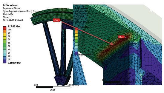
Assembliesofinterestwhich areknown to be problematiccan be tested to failure, virtually, to determineifthe design canhandleanythinga roughmodel engineer trackcan throwatit.
andisrelativelyinexpensive if theoil from your last car serviceisusedasa fuel source esign ratios foranefficient design wasgiven in oneofmy first technicalseriesand as Ideveloped newtechniques over theyears that made the processmoreefficient cheaper or more robust,articleswere addedtothe proverbial casting pot. Newcrucibleadditives were developedtoreducethe melt andprevent gaspickup (photo7). This is practically necessary when meltingfines or copperwhich is notorious forgas pickup.Various green sand mixeshavebeen developed, triedand tested over theyears simply because no localfoundry supplierwas willingtosellsmall quantities to abackyardenthusiast. This is thebestpossibleoutcome becauseitforcesone to be innovative andcookupnew, andinevitably, much cheaper alternatives (ref3).
BecauseI do most of my owncastingsitisrelatively easy to make designer alloys, andoften Itweak theFeSiin cast iron,ortin in copperalloys to getthe required gradefor thejob at hand.One novelalloy wasa specially formulated gradeofalumina bronze that hadalmostidentical characteristicstogunmetal, but wasfreemachining,and not as toughasthe higher strength aluminabronzes.Thisalloyhas effectivelyreplacedgunmetal in my foundrydue to difficulty in obtainingtin as an alloying element(and, no,melting tin solder is notfinancially viable (ref4).
FEAasa thermal structural design tool
FEA(Finite ElementAnalysis) is afantastic tool,usedby modern daydesigners to virtually confirm that adesign is sound. When doingresearch on aspecific prototypeit s
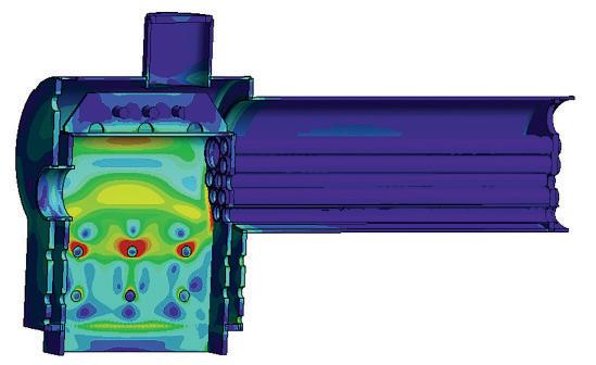
A surfacetensile stress plot to checksensitivity to crevicecorrosion cracking when usingstainless steel as aboilermaterial. This plot also debunksthe misconception that acrownstay places unduestressesonthe foundation ring
always agood idea to check forknown design issues and failuresduringservice.One such exampleiswheel failures on theold largeVictorian era wheels(fg 2). Some of these wheelswereforge welded whichdidn’thelpwithfailure analysis,but once thedesign is done,a virtualmodel canbe pushed to failure,and asanity checkdoneonthe inputforces to make sure themodel will handle high loadingwithout failing.
Boilerdesignhas always been acontentious issueand I’ll elaborateonthatina little more detail. FEAhas been critical in checking thesurface tensile stressesfor allmy stainlesssteel boiler designs. Usingstainless forboilers is nota newidea, butwiththe aidofFEA,crevice corrosion cracking (orstresscorrosion cracking)can be minimisedby strengtheningareas wherethe surfacetension is problematic. FEAhas also shownthat previous misconceptions aboutloading thefoundation ring when usinga crownstay insteadofrod stayshas no basisfor my specificdesigns anditprovedthata crownstay is suitable,and in fact, beneficialwhenfabricating a boilerusing TIG(fg 3).
To be continued.
REFERENCES
Ref 1 Design tractive effort =piston diameter2 x stroke xboiler pressure /wheel diameter
Ref 2 Backyard Foundry Techniques: Pattern Making Using 3D Printing.Model Engineer; vol. 226: 4662, 4663
Ref 3 Backyard Foundry Techniques.2019. Model Engineer; vol. 223: 4626, 4627 and vol. 224: 4628, 4629
Ref 4 DIY Model Engineering Cylinder Alloys.2023. Model Engineer; vol. 231: 4731
71 INNO VA TIO NS www.model-engineer.co.uk
7
Fig 2
Fig 3
ATwi nTan dem nT Compound Steam Engine

Graeme Quayle presents hisown design fora compound winding engine
Continuedfromp.39
M.E.4745 June 14
We’ll continue with the making of thevalve gear forthe TTCSE modelsteam engine (fg 16). Thevalve chests andcovers in this drawinghavealready been coveredina previous instalment,soitisthe other smallervalve partsthathave still to be made.
Thevalve spindleguides, valvespindle guidebushand thevalve spindlegland nuts areall made from 8mm(5/16 inch)brass hexagonbar and
arestraightforward machined parts. Do useplugtapstodo theinternalthreading andnote therecessesatthe shoulders of theexternalthreads -thisis so that theparts screwhard againstmatingsurfaces. On assembly of thespindle guides andthe guidebushtothe valve chests,itisgood practice to bedthemon6 mm copper washers.
TheHPand theLPvalve spindles made from stainless steel areina harder material
that requires averysharp tool to machine. Otherwise, becauseofthe smalldiameter, theturning of the2.2 mm diameter portionparallel will presentproblems. This diameter is notcritical, so do notworry if it is alittle undersize. To do the5BA threadsrequiresa sharp buttondie andthe thread must be paralleltothe axis of the spindle. If youhavenot gota die buthave inch thethreadcan be changed.
Valvechests, covers andslidevalves.
72 ModelEngineer 28 June 2024
PA RT 7
16 16 16 10 10 3 3 5 5 12.7 12.7 8.2 8.2 6.4 6.4 2.52.5 2.5 2.5 2.5 2.5 r2 r2 r2 11 38 38 38 38 26 26 15.5 3 53.5 11 11 11 11 11 11 11 11 2.5 2.5 11 11 11 16 16 19 19 10 10 15 6 9 3 6 6 2.5 2.5 3 3 3 3 10 5 3 6 6 6 3.2 3.2 6 2.5 M6 M6 M6 5BA 5BA 5BA 5BA 71 171 13 13 9 9 28 28 8 8 8 4 Ø6 Ø6 Ø6 Ø3 .2 Ø3 .2 Ø2 .2 Ø2 .2 Ø3.15 Ø3.15 18 18 20 16 7. 4 8. 4 3. 2 2. 5 2. 5 2 .5 2. 5 2 .5 7. 5 20 3. 2 5 40 35 8 8 8 8 8 81 4 14 14 10 10 10 15 10 20 17. 5 40 35 10 15 2. 5 2. 52 .5 2. 5 14 12 3 6 6 28 2 3 3 2 2 r3 r2 r2 Ø2.3 13.5deep 12 holes Ø2.6 12 holes Ø2.6 12 holes Ø2.6 12 holes Ø2.6 Drill Ø3.2 Drill Ø2.65 Tap5BA Drill Ø5.1 TapM6 DrillØ5.1 TapM6 Drill Ø5.7 Tap1/4 x40ME Drill Ø5.7 Tap1/4 x40ME Drill Ø5.1 TapM6 ValveSpindle Guide Mat’l: 8mmhex brass 4off HP ValveChest Mat’l: Aluminium 2off LP SlideValve Mat’l: 12.7(1/2”)brass/bronze 2off LP ValveChest Cover Mat’l: 2.5mmbrass 2off ValveSpindle Nut Mat’l: 3mmbrass 4off ValveSpindle Joiner Mat’l: Steel or brass 2off LP ValveChest Mat’l: Aluminium 2off HP ValveChest Cover Mat’l: 2.5mmbrass 2off HP SlideValve Mat’l: 12.7(1/2”)brass/bronze 2off ValveSpindle GuideBush Mat’l: 8mmhex brass 4off ValveSpindle GlandNut Mat’l: 8mmhex brass 4off HP ValveSpindle Mat’l: Ø1/8”stainless steel 2off LP ValveSpindle Mat’l: Ø1/8”stainless steel 2off Fig
16

However, do remember to change thethreads in the spindlenutsand theknuckle joints andall theother associated parts. Checkthat thevalve spindles arestraight as this smalldiametercan easily getbends in it.The valve spindles should slidefreely throughthe spindleguides. Thevalve spindlenutshave to have thethreadedholes
square to thefaceofthe nuts andthe nuts must be afreefit in theslots in theslide valves This is becausethe slidevalve must be free to seat against thevalve wear plates. Theslidevalveshavea rectangularrecess3 mm deep on theirworking facesand on theouter face twoslots Theshallowerone fitsfreely to thevalve spindles andthe
deeper onetakes thesquare nuts again an easy fit but not sloppy.The valves aremade from 12.7 mm (½ inch)brass or bron e flatbar or plate. The workingfaces must be linished flatwithsharp corners usefine sandpaperona flatsurface Thefinalpartonthisdrawing is thevalve spindlejoiners Photograph 43 showsthe slidevalvesand rods.Mostof
theseparts areshown in fig 16 buta couple of them will be coverednexttime. Nowmovingonto fg 17 and therestofthe valveparts.The reversingquadrants will need abit of lateralthinkingtobe made.Ifyou have access to alaser cutterthenthatisan option.Theycan be milledout by hand butitdoesrequire a setuptodothis. Themainpart is aflat barsome 0mmwide andsufficiently thic say10/12 mm andatleast 00mmorso long.Atone endmount aclosefitting pivotboltthatclampsto your mill tableand allows the flatbar to move radially but notfreely- it needstorequire some effort to move around Drill andtap thebar to pick up thequadrant’sthree holesat there uired140 mm radius andfixthe individual reversing quadrant blanks to thebar with suitable screws.Countersunk head screws areideal.Set up apac erunder theflat barout
KnuckleJoint Pin
Mat’l: 3.175 (1/8”) M.S. 6off
KnuckleJoints
Mat’l: 8(5/16”) sq.brass 6off
Reversingcomponents.
Lift Arms
Mat’l: 1/4” x1/16” brassstrip Ø1/4”brass round 2off @3.175 hole,2 offtap 5BA
ValvePushRods
Mat’l: 3.175 (1/8”) M.S. 4off
73 CO MP OUND ENGINE www.model-engineer.co.uk >>
43 ReversingQuadrant Mat’l: 3.175 (1/8”) brasssheet 2off EccentricStraps Mat’l: 6.35 (1/4”) brassbar 4off Lift ArmPins Mat’l: Ø3.175 (1/8”) M.S. 4off LiftShaft Bearings Mat’l: 1/4” x3/8”brass flat bar 2off Eccentrics Mat’l: 25.4(1”)M.S 3off Eccentric Mat’l: Ø38.1(11/2”) M.S. 1off Lift Link Arms Mat’l: 1/8” x3/8”M.S.flat Ø12M.S.round 2off Lift Shaft Mat’l: Ø5 M.S. 1off 85 2.5 5 5 17 50 60 115 11 11 9 3 Slot 5BA 5BA 2° 2° 8 9. 41 27 .6 1 2. 7 13 .6 9 14 .1 8 33 7. 1 4 3. 18 2. 41 Silver solder 2withholes Ø3.175 2drilledØ2.65, tap6BA Drill Ø2.5 TapM3 Ø10 10 8 4 5 Ø3.175 r4 Ø3.175 Ø3.18 Ø3.18 3.175 3.175 slot 3 8.2 1.02 7.66 r4 r3 r3 r4 6.22 r140 Drill Ø2.5 TapM3 Drill Ø2.65 Tap5BA DrillØ2.5 TapM3 Drill Ø2.65 Tap5BA Oilerholedrill with 3/16” centre drill& thru Ø1.2 Ø20 Ø20 Ø20 r3 28.5 8 4 6.35 3.18 Ø24 Ø25.4 Ø38 Ø10 Ø19 Ø3.2 r2 r6 Ø5 Ø5 Ø7 Ø1 2 12 12 r12.7 5 5 0. 5 6. 5 6. 5 2. 5 2. 5 3 3 6 Ø2.5 holes 10 deep TapM3 3. 5 1. 6 6. 35 3. 18 28 22 86 9.5 19 13 18 5 5 Enlarged detail Enlarged detail 5BA 3 Ø5 Ø6.35 Ø5 r3.18
Slidevalvesand rods
Fig 17
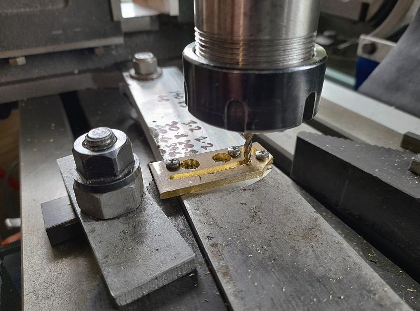
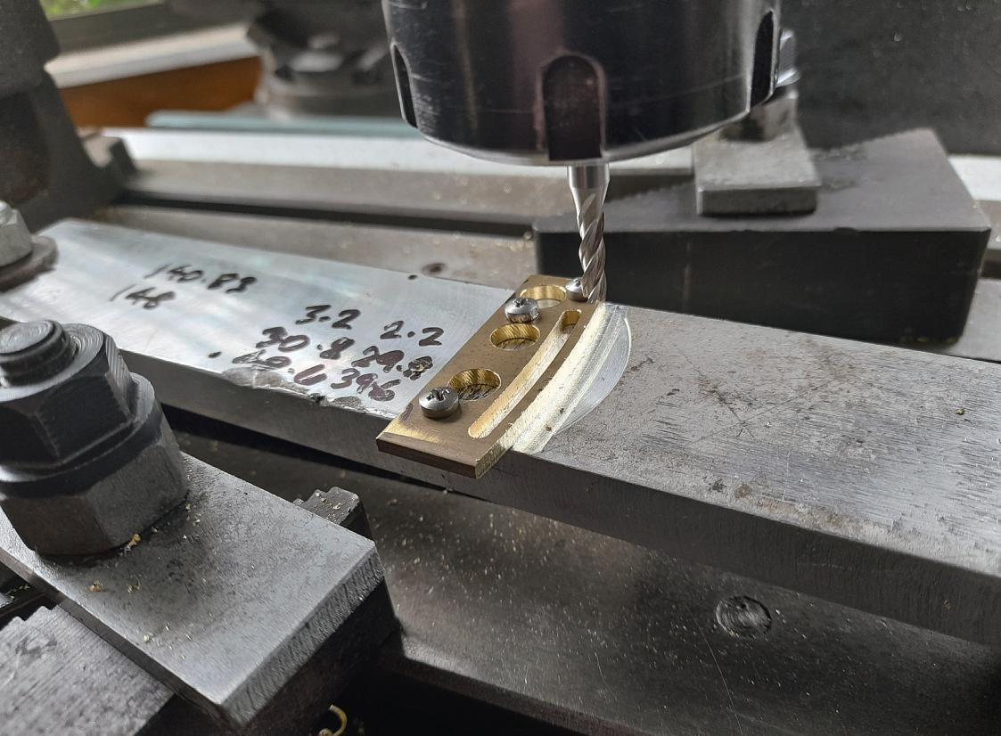
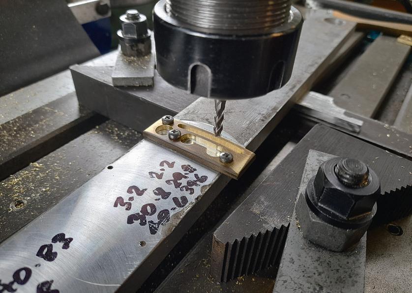
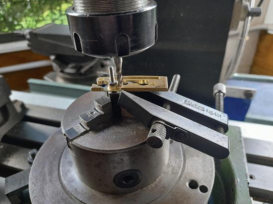
towardsthe free endand if possible, setupa bridge plate over thetop so that theflat bar canstill swivel butistrapped vertically.Next, with saya 3 mm slot drill in themill, set stopsonthe bedofthe mill to theendsofthe slotssothatthe cutteronlycutsthe 33 mm long slot.Lockthe millingmachine’s bed. Startyourmachine and carefully advancethe slot drill down into theworkpiece,while holdingthe endofthe flatbar from moving.Slowlyswivelthe flatbar byhand to startmilling theslot. Progress themilling untilthe slot is completed. Replacethe 3mmslotdrill with a inch oneand open outthe slot.Donot attempttohold theslotdrills with adrill chuck, they arenot ridged enough, usepropercollets.Now the millingmachine’s bedcan be repositioned to mill theouter andinner radii(photo , and 6). Thesmallerradii can
74 ModelEngineer 28 June 2024
outsideradiusinthe quadrant
Firststage millingthe quadrant slot
Millingthe
44 45
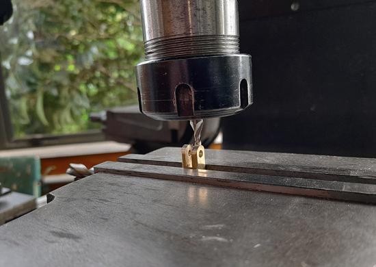
be done with aspigotinthe rotary tableorsimplyformed with alinisher or hand file (photo 7). Thefaces of thequadrants need to be burr free so hand linishthemwithsomefine sandpaper. Theslots should be asmoothfinish to allowthe pin to slidefromend to endinthe slotseasily
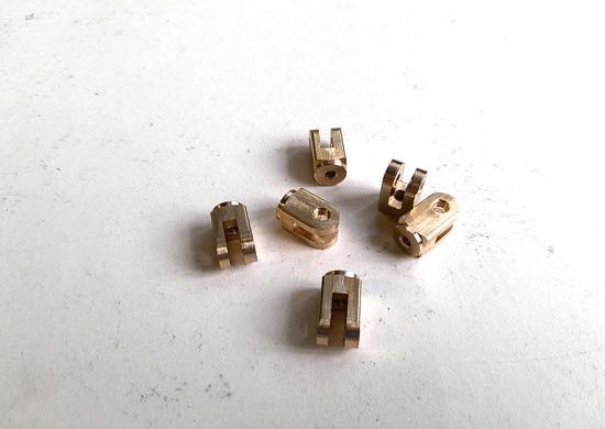
Theprocess to make the knucklejointscan seem obviousbut theway that they were done on theprototype is as follows.The pivotholewas drilledfor thenon-threaded side andthen continued throughwiththe tapping size drill andtapped. It pays to preparethe sixtoeachstage With astubmandrel in the rotary tablethe endradiuswas done (photo ). With aslot drill mill theslot(photo ). Part offinthe lathe, drill and tapthe rodholes (photo ).
75 CO MP OUND ENGINE www.model-engineer.co.uk >>
Millingthe innerradius.
Millingthe pivotradius.
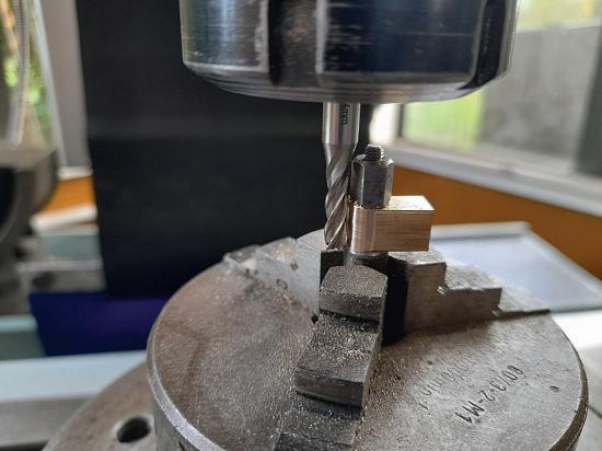
Slotting aknuckle
Millingthe radius on aknuckle
Finished knuckles
46 47 49 48 50

Assembly of slidevalves.
Theknuckle jointpinshave ust sufficientthreadonthem to screwintothe knuckles and lock.Theyshouldnot project more than 0. mmout at either end. Slot them with ajunior hacksawblade.
Thevalve push rods must be allthe same length.Donot bend theendsatthisstagethat will be done later.
Thefoureccentricstraps need to be machined identically from ¼inchbrass.The prototypeonesweremade from x 1inchflat bar the 20 mm diameter holesbeing reamed with an adjustable hand reamer,using slow speed in themill.Theywerethen mountedona stub mandrelin therotarytable andthe radius wasmilled. Theoilerand tappedholecompleted these.
Thethree plaineccentrics were machined to fit thestraps then offset anddrilledand reamed forthe 10 mm hole andwitha partingblade the concentric boss wasmachined, finally partingoff to length.The eccentricwiththe pulleyisa littledifferent as thepulleyis concentric with theboreand theeccentricbossoffset.
Theliftarmsare made from 1/16 x¼ inch brass stripwhich canbebought from modelshops that stock theK &S stocks of metal. Thesearmshavetobeexactly identicalcentretocentre. The bars were drilled4 mm initially andthe bossesmachinedwith spigotstofitintothese holes. Note that thereare pairsof arms some with 3.175mm inch holes andthe others drilledand tapped5BA.The
bossescan be soldered into thearms.
Theliftarm pins arethreaded oneend just long enough to screwintothe liftarmsand end up flush the otherend having twolocknutssothatthe arms canstill pivot. Theliftshaft bearings screwunderneaththe topplate so thetappedholes must lineupwiththose already in thetop plate. Theliftshaft must be able to slidethrough theliftshaft bearings and revolve. Theliftlinkarmsare grub screwedtothe liftshaft paralleltoone anotherand they pick up thelower holesinthe liftarms. Thearmscould be out of brassnot steel buttheymust be silver soldered together
Thefinalvalve controlparts areshown on fig 11 . .4 44 May31).The reverser lifting linkmountsbetween thelink arms andisthreadedfor the reverser liftingscrew.Both partsare self-explanatory and thearrangementonthe model is shownonthisdrawing.The reverser handwheel screws onto theend of thelifting screw andislockedwitha nut. The handwheel needstobeableto rock sideways so that thelower endofthe liftingscrew canjust touchthe sidesofthe 10 mm hole in thereversercolumn. This is to allowfor theradius that theliftlinkarmsswing through. Thereversercolumn screws onto thetop face of the base platewith10mmlong screws from underneath
Setting up thevalve gear
Theeccentricstraps, valve push rods,and theknuckle joints need to be assembledso
that allfourare identical, the only differencebeing that two will have theplain hole in the knucklefacingone wayand theother twothe otherway. Theplain holesfaceoutward so that theslottedheads of theknuckle jointpinscan be accessed. Then thepushrods areslightly bent horizontally so that theknucklescan sit oneabove theother when the eccentricstrapsare sitting side by side.The knuckleendsare bent theopposite wayuntil they matchtogether. Mountthe eccentrics to thecrankshaft with theeccentricstraps.
Slidevalvesand cylinders
TheHPand theLPvalve spindles arepartially slid into theirrespectivevalve chests andthe valvespindle nuts screwedintospindlesabout half wayalong thethreaded portionofthe spindles.Onthe HP spindlerun ahexagon nut onto the9 mm threaded end then thevalve spindlejoiner, locked with anothernut.The LP spindlehas theguide forthe LP valverod looselyput on then a nutonthe 9mmend,the valve spindlejoiner, then aknuckle jointlockedon. This knuckle jointconnectstothe slot in the quadrant butatthisstage do notconnect it (photo 1). This next step is easier to do with thecylinderassembliesnot on thebaseplate butbeforetaking them offmarktheir positions on thebaseplate.Slip theslide valves into thevalve chests over thevalve spindlenuts. Mountthe valvecheststo thecylinderassembliesbut withouttheir covers.Adjust
thevalve spindlenutssothat both HP andLPslidevalves arejustopening andclosing theports in thecylinders at the same time.Makesurethe ends of thevalve spindles arenot bottoming in thevalve spindle guides andthatthe transfer portscan open fully.Mount thecylinderassembly back on thebaseplate andcouplethe quadrant with theouter valve push rodcoupled to theupper mounting in thequadrant. The topquadrantholecouples to theliftarms. Thebottomhole in thequadrantcouples to the innervalve push rod. Have the quadrant in itsdownposition fora start. In turningoverthe crankshaft this will move the valves andtheynow need to be setsothatthe endports open thesameamount. If they do not, adjust thevalve spindle nuts untilbothportopenings arethe same.Rememberboth HP andLPvalve spindlenuts must be adjusted together
To setthe eccentric positions, setthe cranktoTDC andthenturnthe eccentric on thecrankshaftuntil it is aheadofthe cran byabout 90 degrees andthe endtransfer port is just opening. This means theflywheel will runtowards thecylinders.Withthe quadrant in theuppositionthe other eccentricshouldbeabout 1 0 degrees from thefirsteccentric againjustopening theport.
Thevalve chestcoverscan nowbefittedand theguide for the valve rodcan be fixed in placewithtwo screws and nuts
To be continued.
76 ModelEngineer 28 June 2024
51
Pa rt 14 : Hau li ng t he To ys -P ar t4 Hauli

Steve Goodbody takesa random walk through modelengineering.
Continuedfromp.46
M.E.4745 June 14

Inthe previous dramatic instalment,a braveand mathematically inclined cow narrowly escapedinjuryand acarelessdriverdiscovered theDecelerationDemon and lost hisno-claims bonusinthe process.
We re-jointhe tale as the author,trailerinhandand bit between histeeth, is deciding howtosecureeverythingin placewithin.
Ermintrude is presentlyin hiding;I suspectwehavelost hertrust
Afrm anchorage
As with theweakest linkin theproverbialchain,any system is only as strong as itsleast-strongcomponent. When consideringhow to safely secure atractionengine to atransportationtrailer, therefore- or anything else for that matter- it is importantto ensure that each part of the wholeisuptothe job. Knowingthattrailers area commonsight on ourroads in America, haulingeverything from lawnmowers to cars to entire houses (admittedly
less commoninthe latter case), it seemed reasonable to conclude that asizeablesupply market must existfor trailer tie-downsand theirassociated accessories.Tomyhappiness, this indeed proved to be the case anditdid nottakevery long to findseveral websites devotedtothe subject.
Reviewingthese purveyors,
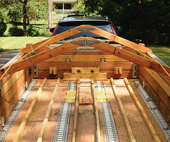
Idiscoveredthatone product range– Erickson’s E-Track (named here andelsewhere with theusual disclaimer, although Iamopentooffers should themanufacturerwish to reward me forthe unbidden advertising!)- appeared to be both commonlyavailable, well-endowedwithinteresting attachmentsand eminently adaptablethankstothe clip-in/clip-out nature of thoseattachmentswiththe E-Track mounting strips which form thefoundationalparts of thesystem(photo52). Furthermore, as Ireviewed thepictures specifications andloadratings,someof theavailableitems seemed ideally suited to my somewhat unusualapplication. Convinced that this mightbea viable solution,I returned once again to thetrailer’slayoutdrawings and, aftera bitofthought to determinethe best location forthe mounting strips to suit theloading plan,I assembled an order, parted with my credit
payloadmounts.
77 www.model-engineer.co.uk >>
E-Track system as thebasis
trailer’s
TheauthorselectedErickson’sversatile
forhis
52

Ahundred (orso) quarter-inch diameter stainlesssteel fasteners, alllock-nuttedto be sure,securethe E-Track strips to thetrailer sfoor andchassis.
is only as strong as itsweakest link, afterall.
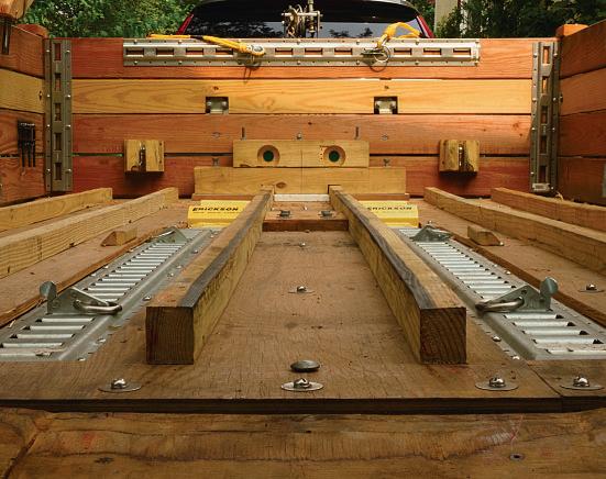
Half-inchexterior-gradeplywood sheets arealsofastenedthrough theoriginal foorboards to thechassis, creating asturdycomposite sandwich
card details once againand waited forthe packages to land upon thedoorstep
Thefollowing weekend, thehold-down paraphernalia having duly arrived, Iset to work,planinhand, to installthe impressively sturdy mounting strips within thebed of the trailer. Realising, likethe aforementionedweakest link, that theseitems wouldbeuseless if they were themselves not securely attached,I beganthe lengthyprocess of installinga hundredorso¼-inchdiameter stainlesssteel screws into theattachment holes, thence into holespainstakingly drilledall theway throughthe trailer’ssubstantially-planked
extremelystrongcomposite sandwich andprevent individual planks from breaking free to releasethe mounting strips (and my precious cargo) even if,heavenforbid, the trailerwas upendedorperhaps even overturned (photo54). While thetheoryis, Ibelieve, sound, Isincerely hope that it is nevertestedinpractice!
Andso, with the E-Track mounting strips firmlyattached to both thetrailer’sframe and thenow-reinforcedcomposite floor the next item on the agenda loomed.How to get RubySwann into thetrailer in thefirstplace and safely back down at theend of each journey?
Heave-ho
Now, tryasI might, andI did try, it is sadlytruethatI do notpossess thestrengthto push RubySwann,all three hundredorsokilograms of her dainty Allchinframe,upthe ramp andintothe trailer. And knowingthatshe is unlikely to getlighter andI am unlikely to getstrongerinmydotage, it seemed prudenttoinstall an aide mécanique,asour Gallic friendsmight say, to get hersafelyintoand outofher conveyance.
Over theyears Ihaveused avariety of winchesfor a rangeoftasks and, broadly
speaking,theyfallintotwo main categories –those that don’tmovewhenyou stop them andwalkawayand thosethatdo. Andofthese, andespeciallywhenworking single-handedly, Istrongly prefer theformercategory. However, as yousurelyknow, it is largelythe winch’sgear ratiowhich determines whether it will stay putwhenyou are checking what’s goingonat theother endofthe cableor beginspinning wildly to deposit your previous load back at itsstartingpoint in ahurry;a winchwitha high gear ratiowill notmovewhile alower-geared varietymight.But there’sa penaltytopay fora highly geared winch; it takesa heck of alot more handle turningto move theloadany distance. Of course,one solution is to useanelectricwinch –a motor doingthe jobatthe pressofa button– andthatwas certainly an option.However,and being an awkwardso-and-so,I am nota fanofelectricwinches; in my experience either the battery dies or themotor conks outata critical juncture andthe operator,now unable to move theprecariouslysuspended load in either direction finds themself up theproverbial creek withouta proverbial paddle. No,whatI wanted wasa nice,simple, manual,
wooden floor andfinally wherepossible, threadingand lock-nutting them directly to thetrailer’s frame, allwith shakeproof andlarge-diameter washerstoprevent anychance of theirlooseningunder normal useorpullout in theevent of an accident.Overkillperhaps, butbettertobesafethansorry (photo53).
With theseinplace,next came sheetsofhalf-inch exterior-grade plywood,with cut-outs to avoidthe mounting strips,all similarlyattached to thetrailerwithanother hundredorsofasteners.These sheetswould,I reasoned,by tyingall of thefloorplan s together from above, create an

78 ModelEngineer 28 June 2024
chain
Thewormdrive winch, itshandleremoved andreplacedbytwo locked nuts
54 53 55
high-ratio winch, capableof getting thetractionengine up therampinlessthantwo minutes, requiringlittleeffort from yourstruly in theprocess, andallowing me to walk away mid-pull withoutfearofan uncontrolleddownhilldescent. Oh yes, andI didn’t want it consumingvaluableload-bay spacewithinthe trailer.
Nowbeforeyou poohpooh this seeminglyabsurd mishmash of conflicting goals, doubting Reader,let me assure youthatsucha thing is possible, givena littlebit of lateralthinking. Forifyou, as I, owna modest batterypoweredportabledrill, then youare alreadynine-tenths of theway there. Andifyou still don’tbelieve me, photos 55 to 58 hopefully explain my particular solution – visá-viz:a worm-drive high ratio winch, itshandleremoved from thethreadeddriveshaft andreplacedbytwo nuts locked together,a two-speed battery-drill to providebothfast andslowmotivepower and asocketspanner, mounted in thedrill’s chuckwiththe appropriateadapter,totransfer thetorquefromone to the other. Andwiththese simple provisions anda nonchalant grin to theincredulous onlookers, Ruby Swann will steadily ascend or descendthe ramp undercompletecontrol andstaywhereshe is putinthe meantime when needed.And should thedrill or itsbattery
57

56
The winchisboltedtoa substantialshelf abovethe towbar;readily accessiblewithout consumingvaluablepayload space.
fail, although Ikeepa fully chargedspare battery in my toolboxasa precaution,I can simply remove thosenutswith acoupleofspanners, return the windinghandletoits intended place, spit on my palmsin preparationand finishthe ob by hand.Fortunately,I haven’t hadto– yet.
Andifyou,likeme, decide to useanopen-toppedtrailer, then youmay want to consider mounting your winchona
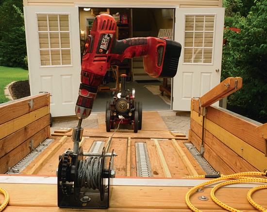
sufficientlyrobustforward facing shelfabove thetowing hitchframe whereitwill always be readyfor use, easily accessiblefrombothinside andoutside thetrailerand yet consumenoneofthe valuable load-bay spacewithin. Forme, threeyears on,ithas worked likea charm.
Chocks away
With ahandy winchtodrag thetractionengineaboard,
58
sturdymountingstripstohold herinplace once thereand a substantialplank-and-plywood compositefloor to transfer theloads evenly to thetrailer’s frame- andhopefully prevent catastropheinthe eventofa majorupset en route- allthat remained wastodetermine exactlyhow to anchor Ruby Swann to thosemounting strips.And this,believe it or not, wasthe simplest part of theentireprocess because

79 BUT TERS IDE DO WN www.model-engineer.co.uk >>
Thewinch with portable drill in position,all readyfor use.
Ruby Swann begins herdrill-poweredascentintothe trailer.

(while reiteratingthe usual disclaimer regardingthe manufacturer)the reason Ihad chosen the E-Track system in thefirstplace really came down to acoupleofgadgets depicted in thecatalogue,evidently intended forthe securing of all-terrain vehicles (orATVs,
as they arecommonlyknown) andautomobiles,yet seemingly idealfor thejob of holdingmy weightytractionenginefirmly in place.
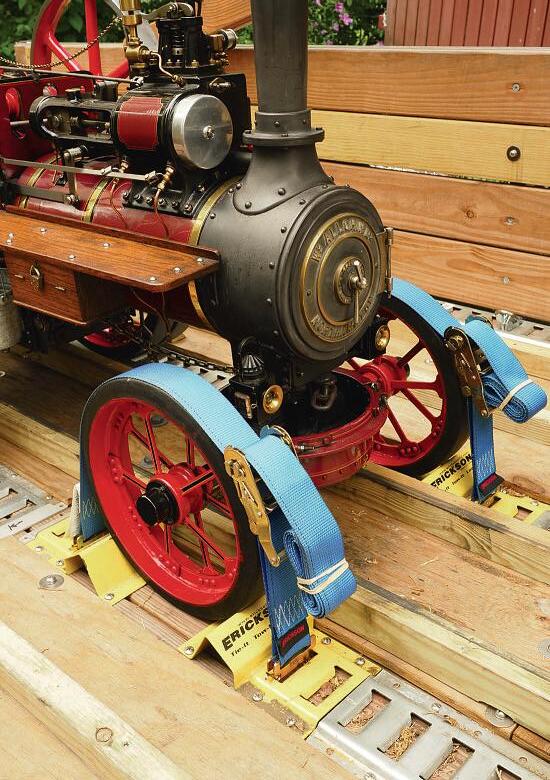
Thefirstofthese items listedinthe manufacturer’s onlinecatalogue as a‘Wheel Chockand StrapKit’ (Erickson part number 09160,should youeverwishtorefer)and typically intended to secure the aforementioned ATVs,consists primarily of four cunningly designed mounting strips,a pair foreachwheel andhaving an integrated wheel chock apiece,positionedone in front andone behind each wheel to constrainits movement.Thus, with four wheel choc s firmly bolted throughthe trailer’s floor in theappropriate place (photo )and afterrolling RubySwann’s frontwheels over therearmostpairto nestle in thespace behind the foremost two, aratchet strap -alsoprovidedwiththe kit– is placed around thetop of each
61
80 ModelEngineer 28 June 2024
Hertwo frontwheelstightly boundbythe ATVkit’s ratchetstraps.
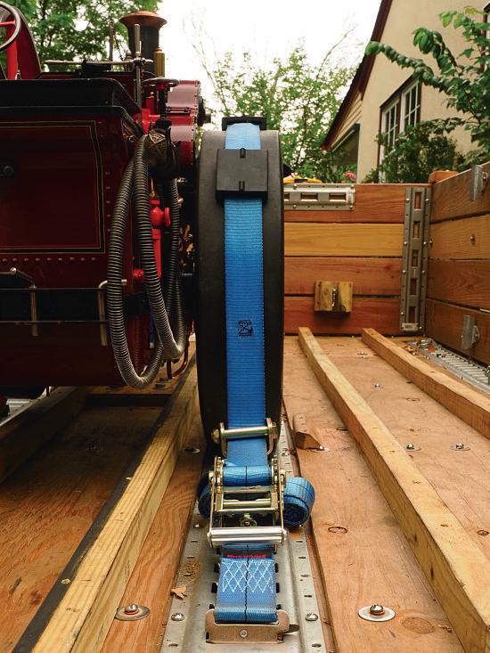
Forthe rear wheels, theRatchet StrapwithRollerIdler kitincludesthree rubber wheel padshavingtriangularprotrusions on each side,ideal to locate with the groovebetween Ruby Swann’svulcanisedtyres
Erickson’s ATV(All-Terrain Vehicle) wheel chocks were idealfor securing Ruby Swann’s frontwheels.
59
60


 MARTIN EVANS Editor
DIANE CARNEY Assistant Editor


