


Persuadinga Congreve clock to keep time
Miniature Jet Engines

❖❖
More on propane burners Atender chassis forLNWR 2-2-2
KE EP IN GT IM EW IT HA CO NG RE VE CLOC K TH EO RI GI NA LM AG AZ IN EF OR MO DE LE NG IN EE RS Vol. 232 No.4744 31 May– 13 June 2024 Join ouronlinecommunity ronlinecom ty www.model-engineer.co.uk r.co
Cornwall Acquiring afirst steam st engine

PublishedbyMortons MediaGroup Ltd,
MediaCentre, Morton Way, Horncastle,Lincs LN96JR
Tel: 01507 529589 Fax: 01507 371066
©2023 MortonsMedia ISSN 0026-7325 www.model-engineer.co.uk
EDITORIAL
Editor: Martin R. Evans
MEeditor@mortons.co.uk
Deputy editor: DianeCarney
Designer: DruckMedia Pvt. Ltd.
Club News: GeoffTheasby Illustrator: GrahameChambers
Publisher: SteveO’Hara
CUSTOMER SERVICES
GeneralQueries andBackIssues 01507 529529 Monday-Friday: 8.30am-5pm Answerphone24hr help@classicmagazines.co.uk www.classicmagazines.co.uk
ADVERTISING
GROUPHEADOFINVESTMENT– Lifestyle& TractorPublications |www.talk-media.uk MasonPonti mason@talk-media.uk
A: Talk Media, TheGranary,Downs Court, YaldingHill, Yalding, Kent ME18 6AL
Investment Manager: KarenDavies karen@talk-media.uk
PUBLISHING
Salesand distribution manager: Carl Smith
Marketingmanager: Charlotte Park
Commercialdirector: NigelHole
Publishing director: DanSavage
SUBSCRIPTION
Full subscription rates(butsee page 726for offer): (12months, 26 issues,inc post andpacking)–UK £132.60. Export ratesare also available, UK subscriptionsare zero-rated forthe purposes of ValueAddedTax Enquiries: subscriptions@mortons.co.uk
PRINTAND DISTRIBUTIONS
Printedby: WilliamGibbons &Son,26Planetary Road,Willenhall, West Midlands,WV133XB Distribution by: SeymourDistributionLimited, 2EastPoultry Avenue,LondonEC1A9PT
EDITORIALCONTRIBUTION
Accepted photographsand articles will be paid for upon publication. Itemswecannotuse will be returned if accompaniedbya stampedaddressed envelope andrecordeddeliverymustclearly statesoand enclosesufficient postage. In commonwithpractice on otherperiodicals,all material is sent or returned at thecontributor’s ownriskand neitherModel Engineer, theeditor, thestaff norMortons MediaLtd canbe held responsiblefor loss or damage,howsoever caused.The opinions expressedinModel Engineer arenot necessarily thoseofthe editor or staff. This periodical must not, withoutthe writtenconsent of the publishers first beinggiven,belent, sold,hired outor otherwisedisposedofina mutilatedcondition or in otherunauthorisedcover by wayoftrade or annexed to or as part of anypublicationoradvertising,literary or pictorialmannerwhatsoever.


http://www.facebook.com/modelengineersworkshop

http://twitter.com/ modelengineers


Vol. 232 No.4744 31 May –13June 2024
728 SMOKERINGS
News,views andcomment on theworld of modelengineering
729 BUILDING 3020 CORNWALL IN 5INCHGAUGE
JimClarkbuildsa modelofFrancis Trevithick’s LNWR 2-2-2locomotive.
734 CONGREVE CLOCK
IanBeilbyexplainsthe stepsneeded to persuade aCongreveclock to keep reasonable time.
739 BUTTERSIDE DOWN
SteveGoodbody returnswithfurther tales of thetrials andtribulations of amodel engineer’s life.
744 SMEE NEWS
Martin Kyte reportsfromthe SocietyofModel andExperimentalEngineers.
746 ENGINEERINGSURFACE FLATNESS
Neil Raineexplainsthe definition of surface flatness andhow it is achieved in practice
750 ATWINTANDEMCOMPOUND STEAMENGINE
Graeme Quayle presents an interestingdesign fora compound windingengine.






754 AN ADMIRALTYCASEFOR A REGULATOR
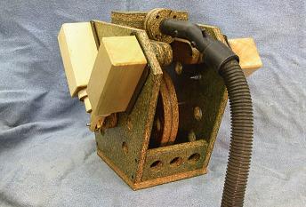
Adrian Garner showsthatmakinganelegant case fora regulator timepiecedoesnot requiresophisticated woodworkingskills
756 MY FIRSTSTEAMING EXPERIENCE
ChrisRayward remembersthe acquisitionof hisfirst locomotive
759 OSCILLATINGENGINEDESIGN
Martin Gearingtakes alook at some novel approaches to oscillatingengines
762 POSTBAG
Readers’ letters
765 MINIATUREGAS TURBINES –AN INTRODUCTION
TimColes explainsthe applicationofgas turbines to modelengineering.
768 LNER B1 LOCOMOTIVE
Doug Hewson presents atruetoscale fiveinch gaugemodel of Thompson’s B1
772 CLUB NEWS
GeoffTheasby compilesthe latestfrom modelengineering clubsaroundthe world.
775 CLUB DIARY
Future Events.
E CO VER
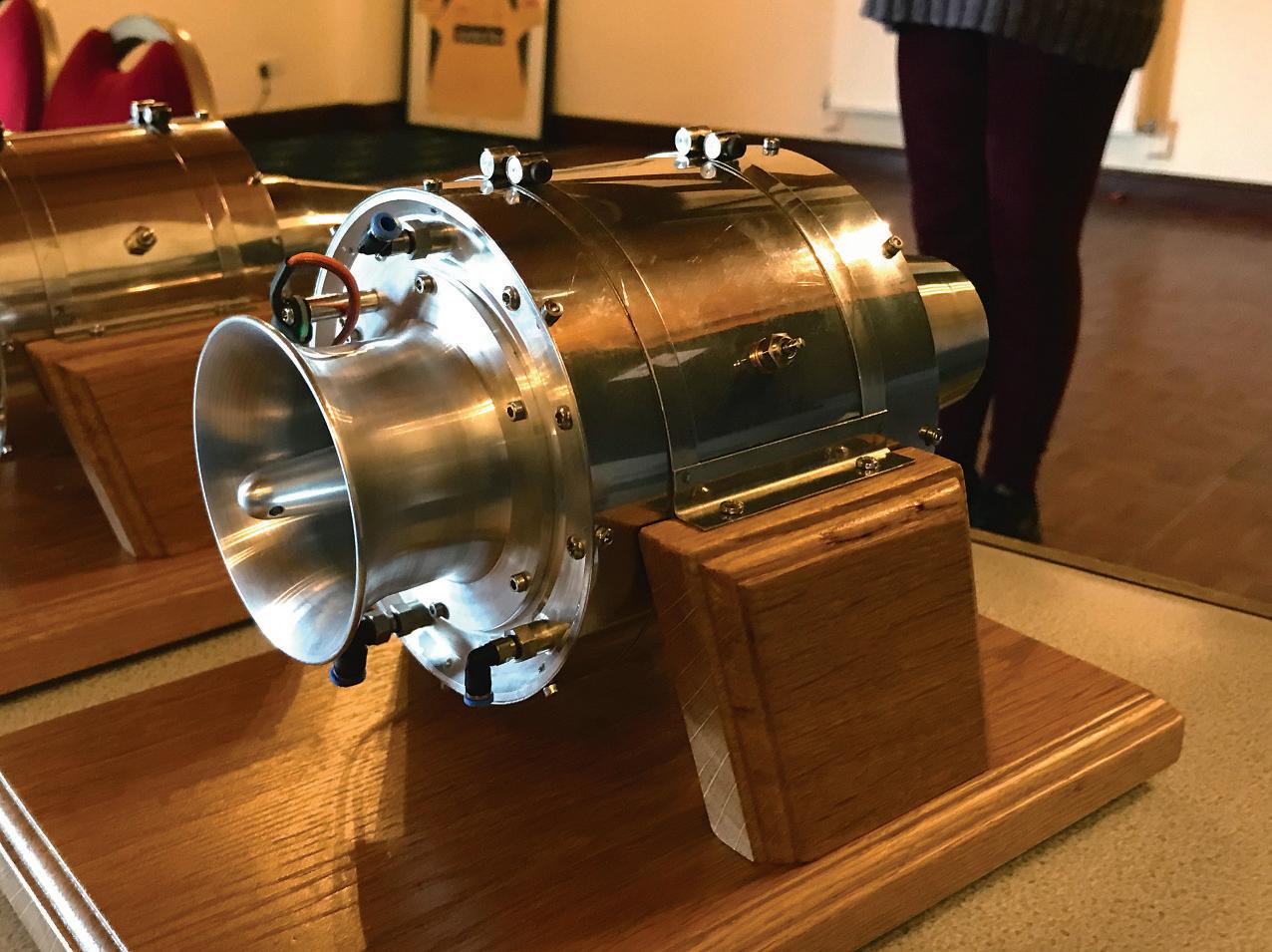
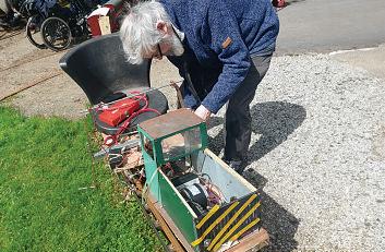
An earlyminiature workingjet engine developedbyJerry Jackmanand histeamin the1970s (photo by TimColes).

www.model-engineer.co.uk 723
ON TH
...
This issuewas publishedonMay 31,2024. Thenextwill be on sale on June 14, 2024. Persuading a rsuading Congreve ve clock to keep ep time More on propane burners Atender chassis forLNWR 2-2-2 Cornwall Acquiring quiring afirst st rst engine KEEPINGTIMEWITHA CONGREVE CLOCK THEORIGINALMAGAZINEFOR MODELENGINEERS y– ng Miniature Jet Engines SUBSCRIBE&SAVEUP TO49%Seepage726for details www.model-engineer.co.uk 772 759






















www.model-engineer.co.uk
SUBSCRIBE ANDSAVE
Enjoy12monthsfor just £68

PRINT

ONLY



PR
Quar terly direc tdebit for £19
1year direc tdebit for £68
1year credit/debit card for £74

INT +D IGITAL




DIGITAL ONLY
Quar terly direc tdebit for £22*
1year direct debit for £85*
1year credit/debit card for £88*
1year direc tdebit for £50*
1year credit/debit card for £54*

*Any digital subscription package includes access to theonlinearchive.

>> Free UK deliver ytoyourdoor or instantdownload to your digital device
>> Save moneyonshop prices >> Nevermiss an issue
>> Receiveyourissue before it goesonsale in the shop
Greatreasons
to subscribe








classicmagazines.co.uk/ MEDPS 01507 529529 and quote MEDPS Lines areopen from 8.30am-5pm weekdays GMT Ofer ends De cemb er 31,2024. Subscriptionswills tart with thenex tavailab le issue. Dire ct De bitp ay ment swillcontinueonthe agre ed plan unless youtellusother wise Tov iewthe privac yp olic yfor MMGLtd (pub lisher of Mo de lEngineer),p leasev isitw ww.mor tons .co.uk /privacy Please vi si tw ww.c lass ic maga zi ne s.co.u k/te rm sfor fu ll te rm s&cond it ions .
BournemouthCentenary


 MARTIN EVANS Editor
DIANE CARNEY Assistant Editor
Ihavebeen informed that the Bournemouthand District SocietyofModel Engineers celebrates itscentenary this year.The formationofthe societywas announced in alettertothe editor of this magazine on March13th1924. TheSociety website (littledownrailway.org uk/bdsme)providesa very interestinghistory of theclub, describing itsfrst trackatSouthbourne,thenthe move to theCivil Servicesports ground and, abouta decade later, to KingsPark. This track eventually became unavailable, with theexpansion of the football club,and theSociety made itsfnalmovetotheir LittledownParksitein2004. It’s interestingtonotethatthe move to theCivil Servicesite wasfacilitated by oneD.E ‘Laurie’ Lawrence,a former editor of ModelEngineer,who worked at thetimefor Post ffceTelephones. Furtherexploration reveals an interestinglittletwist in the history. In theDecember14th 1944 issue, Percival Marshall announcedthe formationofa newclubatBournemouth.A week later(we were aweekly magazine then), he wrote:
Sincewriting my note about theformation of anew society at Bournemouth, Ihavelearned that thepreviousBournemouth Society, whoseactivitieswere suspendedin1940, hascome to lifeagain.A friendly approach by theold memberstothe new body hasresultedinthe very
Table1
GravityEscapementClock

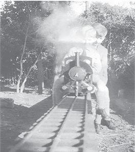
Mortimer family ride theB&DSMEtrack at Southbournein1948 behind Falcon.
desirableamalgamationofboth membership andinterests,and with this additional strength, thecombinedsociety may look forwardtoa long and successful career
Andsoithas proved -my congratulationstothe club!
Cock-upCorner
It lookslikethiscould become aregular featureand this time it’s amajor item!
Firstly, Ihavebeen takento task forclaimingthatBenjamin Franklin ‘coined’ theword battery to refertoVoltaic piles or Leyden jars.Well, of course, Iamaware of theuse of the word in amilitarycontext so perhapsa betterchoiceofword
Mar tin Evans can be contacted on the mobile number or email belowand would be delighted to receive your contributions, in the form of items of correspondence, comment or ar ticles. 07710-192953 MEeditor@mortons.co.uk
In RogerBackhouse’s article on Hunslet’s Scootacar (also M.E.4742),the designer is namedasHaroldBrown.He wasinfactHenry.Hewas sometimesreferredtoas ‘Harry’, whichofcourseisa ‘dualuse’abbreviation for either Harold or Henry, hence theconfusion
Cuefor asong– ‘You say Riley, Isay Raleigh, Raleigh, Riley, Henry, Harry …’.
More exciting episodes of ‘Cock-up Corner’are promised in future issues
Claude B. Reeve ModelEngineer 26 May1960to21July1960
AWeightDrivenRegulator Timepiece Claude B. Reeve ModelEngineer 6May 1966to7 October1966
AWatchmaker’sWorkshopRegulator
An EnglishRegulator, Machined andConstructed
ARegulator Clock
Month-goingRegulator Clock
Making aRegulator to aNew Design
Alan Timmins HorologicalJournal March1981toMarch 1983
John Wilding Timecraft November 1981toOctober 1982
PeterHeinmann ModelEngineer 12 February 1999 to 24 September1999
PeterHeinmann ModelEngineer 28 November 2002 to 11 July 2003
John Reynolds HorologicalJournal January2015 to February 2016 mighthavebeen ‘adopted’. That’llteach me to be alittle more preciseinmyuse of English. Secondly,I’m told the motorcar featured in Club News (M.E.4742again)and labelledasa ‘Raleigh’isinfact a‘Riley’.It’sgoodtoknowthat at leastsomereaders of this journalare awakeand alert! Arathermoreserious issuearose in thefrstart of theseriesonthe Admiralty clockcasebyAdrianGarner (M.E.4742, May3). This wasentirelymyfault so my apologiestoAdrian. When compilingthe tablelisting articles aboutregulator clocks Imanaged to transcribe the data incorrectly (I blamean interruptionbythe manfrom Porlock…). Thesimplestthing to do is to reproducethe correct versionofthe table, so here it is
ModelEngineer 31 May2024
728
Threeyoungstersfromthe
Bournemouth& District SME
BUILDING 3020 BUI LDING
in 5Inch Gauge aug

JimClark buildsthe famous LNWR 2-2-2– thefrst locomotive earmarked forpreservation.
Continuedfromp.712
M.E.4743 May17
PA RT 7
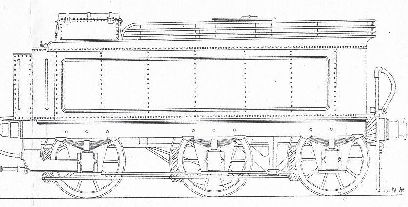
Thetender
Someonesaidtomemany yearsago that when buildinga locomotive,besuretobuild the tender frst,otherwise youwill be temptednot to bother with it once youhavecompleted the locomotive itself.I must admit to fallingintothistrapmyself somewhat,asonce Cornwall wascompleted to this stage, it took abackseat, or rather back bench, forovera year before I
gotsuffciently re-enthusedto fnishit.
Thefrsthurdletoovercome wascompletingthe design drawings,which hadstalled. Thereare plenty of good side andfront viewsofthe locomotive,but notmanyofits current tender,and none taken from above, so it washardto know howthe internal details of thetenderwereactually laid out.
19 Fig 20
In theend,I followedthe outlineinJ.N.Maskelyne’s book (photo52), with details addedfromthe selectionof photographsthatI didhave. TheinternaldetailI assumed from similartenderdesigns, andfromwhatwould be practical, both forthe model andonthe full-size original Figures19 and 20 show my ownelevation drawings of thetender, whichisnoted
729 www.model-engineer.co.uk >>
WALL
CORNWALL
L&NWRStandard 1800 Gallon TenderIn5"Gauge Overalldimensions:520mmlong x235mmwidex 250mmhigh Weight (empty): 12kg 182 165 513 FrontView Rear View Waterfeed from tender Waterfeed from hand pump 174 116 11 212 210 34 36 192 186 11 2 160 166 212 10 26. 5 174 116 11 192 186 160 166 14.5 170 100 8. 5 22 52
Tender side elevationasdrawn up.Tenderend elevations
drawingofthe tender for Cornwall (source: LocomotivesI have Known,J.N.Maskelyne pp.86-87)
Fig
Sideelevation
View Underneath Tender Showingapprox.positions of fittings
Locating holesfor studsin base of tender tank
Brazecompleted chassisframe to tender chassistop plate
Tender ChassisTop Plate
Mat’l: 1.6mmMSsheet
Brazespringpadsto outerframe plates
Tender OuterFrame Plate
Mat’l: 3mmMSplate,2 req’d
FramePlate Spacer
Brazefront andrearstretchers between innerfraqmeplates
Brazeinner& outerframe plates together with framespacers
Tender InnerFrame Plate
Mat’l: 3mmMSplate,2 req’d
Axle
Tender chassisdetails
730 ModelEngineer 31 May2024
Mat’l: MS,6 req’d Horn StaysAnd
Keeps FabricatefromMS& brazetogetherintoone unit 2req’d,L &RH Overflow Water filter outlet Water pump outlet Waterpump Position of framespacer Position of framespacer
8 34 28 148 131 34 34 58 58 15 5 10 2. 4 Ø3 19 6 497 492 495 80 10 6 35.7 35.7 200 120 15 0 40 95 277 186 360 442 15 6 26 .5 25 25 Fig 21
FrontBufferBeamInner
Mat’l: 3mmMSplate
FrontStretcher
Mat’l: 3mmMSplate
FrontBufferCentre
Mat’l: 12mm closegrain hardwood Varnishorclear coat
Rear Stretcher
Mat’l: 3mmMSplate
FrontBufferBeamOuter
Mat’l: 1.6mmMS
FrontBufferBeam
Mat’l: 5mmMSplate,1 req’d
FrontBufferBeamHookPlate
Mat’l: 1.6mmMS
Rear BufferDragBox
Mat’l: Fabricated 5mmMSplate
Drag BoxBase
5mmMSplate
FrontBufferBeamStretchers
Mat’l: 5mmMSplate,2 req’d
Drag BoxSides
5mmMSplate
Tender Horns
Mat’l: 5mmMSplate,6
Rear BufferBeamStretcher
Mat’l: 5mmMSplate
731 CO RNW ALL www.model-engineer.co.uk >>
Mat’l:
Mat’l:
req’d
Csk. from behind andbraze in long 8BAscrewstosecurebuffers Brazeorweld drag boxtorear bufferbeamstretcher Drill &tap M6 or 1/4BSW Bolt on bracketwith couplingtosuitridingcar 192 26. 5 166 166 67 166 166 110 38 18 30 54 42 10 7 35 88 16 .5 74 Ø8 50 10 160 35 13 12 Ø8 210 112 34 18 20 25 30PCD 63 9 5 8 53 14 212 36 20 25 13 25 15 25 70 15 Fig
Tender chassisdetails (continued).
22
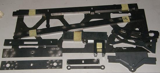
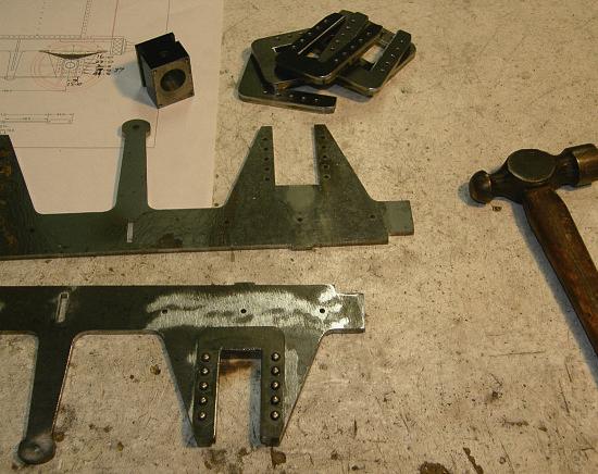
Once again, thesteel chassiscomponentswentout forlaser cutting andsoon akit of partsarrived.
inJ.N.Maskelyne’s book as a‘standard 1,800 gallon L&NWRtender’,and whichwas introduced to theL&NWR by FrancisWebbin1874.These tenderswerewidelyused with otherlocomotives of theperiod, butthisparticular tender wouldonlyhavebeen paired with Cornwall relatively recently,since it entered preservation Thesestandardtenders included ahand-loweredwater
scoop,totakeadvantage of thewater troughsintroduced by John Ramsbottomand used on theL&NWR to allowlonghaul running withoutstops However, that is onedetailthat Idecided nottoinclude in the modeltender, complexenough as it is!
Imadethe tender in two parts– acompleteunderframe chassis, with aseparatetender body sittingontop.Thismakes fora strong androbustchassis,

732 ModelEngineer 31 May2024
53 54 55 56 57
Assemblingthe axle hornblocks
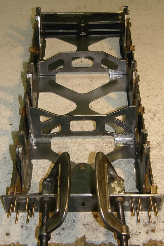
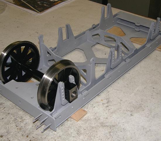
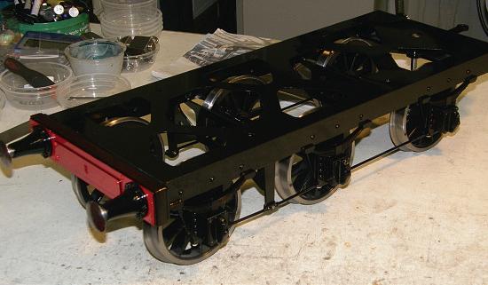
Framecomplete, testinga wheel andaxleset forcorrect ft in thehornblocks.
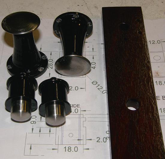
Theaxleboxes andcovers.
The frameclamped up forbrazing
allinsteel,withthe more delicatetankparts allinbrass sheet sitting aboveit(figs21 and 22).
While waitingfor the lasercutting (photo53), I busied myself making up the variouschassis fttings, such as buffers,axleboxes and suspension springs. These were allfttedtothe completed chassisframe lateron, once that wascompleted (photos 54 to 58).
Tender springs
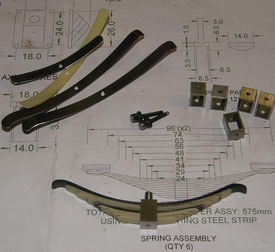
Exterior leaf suspension springsare aprominent feature of thetender, as canbeseen in thesideelevation drawing. So,I decidedtomakeworking scalesprings,ratherthanusing dummy spring shapes with a coil spring hiddeninside, as is oftendoneonmodels. This did addsomenew complexity and
challenges butthat’swhatit’s allabout!
Iestimated that thesprung part of thetender(excluding unsprung partssuchas wheelsand axles) wouldweigh somewherearound10-12kg Icalculatedthe volume of the waterspace to be around 6 litresso, when full of water, the totalsprungweightwillrise by another6kg to about16to 18kg.Incidentally,the model watercapacitycompareswell with theoriginaltender; the volume scales down by the scalefactorcubed,so1,800 gallons in full size reducesto 1.35 gallonsat1/11scale,or 6.2litres.
As thereare sixwheels, the loadingper wheel will be in therange of 2kgto3kg.This worked outthatI wouldneed somewherearound3mm of spring travel per1.5kg load
Thereisa totalof6mm travel in thesprings andwewantthe axlessitting in themiddleof theirtravelrange when unladen andnot bottoming outwhen thetenderisfullofwater FellowNDMES club member Phil Hartleykindlysuppliedme with asheet of 0.8mmthick spring steel.I hadnorealway of estimating thespringforce of this steel sheet fora given width/length,soI just went aheadand cutoff some 6mm wide strips whichI bent up to therequiredshape.The two longestspringleaveswhich areincontact with theslipper plates underthe chassis obviouslydomostofthe work, andsomerough testsI didwith adigital scaleshowedthat thesetwo spring strips alone wouldgivea deflectioninthe orderof2-3mm with a1.3kg weight applied.
Fortuitously this wasjust aboutright!
Phil also gave me some similarthickness Tufnol sheet This is very flexibleand is suitable formakingdummy spring leaves whichcan be inserted into thespringstack withoutadding anyactual spring force. Ifollowedthe toptwo steel leaves with three Tufnol ones,thena steel one, then more Tufnol strips to complete thestack
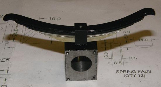
Onetrick Ilearned:before cutting theTufnolstripsto fnishedlengthI coiledthem inside around tincan and heated it gently with ahot air gun– when cool andremoved from thecan,the Tufnol strips retained thecurvedshape they need forthe spring stack (figs59 to 61).
To be continued.
733 CO RNW ALL www.model-engineer.co.uk
58 60 61 59
Thebuffers andwooden rear bufferbeam.
Here is acompleted spring on itsaxlebox.
Component partsfor theworking leaf springs.
Thesprings mounteduponthe completedtenderchassis.
Co ngr ev eC loc k

IanBeilby explains howto getthe best outofa notoriouslytrickyclock
Iam sure most readersof ModelEngineer arewell awareofthe infamous Congreve Clock, aclock which, love it or hate it,has a reputation andfascination like no other.
Withouta doubtithas its many critics. As aclock,even when workingatits best,itis anotoriously badtimekeeper, so much so that many people totally disregarditasa timepieceatall. In fact Ihave heardmanyserious clock collectorssay it isn’treally
aclock,but an engineering novelty, likea clockworktoy
To many owners,and even some repairers, it canbea nightmaretorepairormanage to make it run. Andyet, despiteits badreputation, it is captivatingtowatch andhas an attraction more than any otherclock that Iknowof.
It hypnotises allages, from childrenasyoung as four to adults in theireighties.
Thevisualattraction of the ball continuously zig-zagging backwardsand forwards is
mesmerisingand holdsthe viewers’ attentionwhenever aCongreveclock is puton display.
Thereisnodoubt that they arediffcultclockstomakeand adjust,the fuséemovement andframework area challenge, letalone thetilting tablewhich is atotally alienconcept to a clockmaker
This is probably thereason that formanyyears most Congreve clocks were made by modelengineers, well known forovercominga challenge andtacklingdiffcultpro ects, employingmanyengineering techniques unfamiliartoa clockmaker
Theclocksbeguilement did create alimited commercial market andsomenotable frms of clockmakersdid start to producethem; however they were notmadeingreat quantities andassuchwere quiteexpensive
Irrespective of themaker or manufacturer,these clocks arestill diffcult to setup correctly.Inoperation they rely on gravity, perfectadjustment andbeing absolutely levelinall directions;any slight deviation will result in theclock stopping It requires agreat deal of patience,understanding and observationtoset theseclocks up correctly
QuiterecentlyCongreve clocks have startedtobe manufactured in Asia and exported to Americaand Europe,and they arenow more commonlyseen than in the past.
Themajorityofthese newerclocksare bought via theinternetand quitea few secondhand Congreve clocks arenow appearingregularly in sale roomsand online auctions
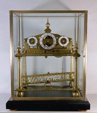
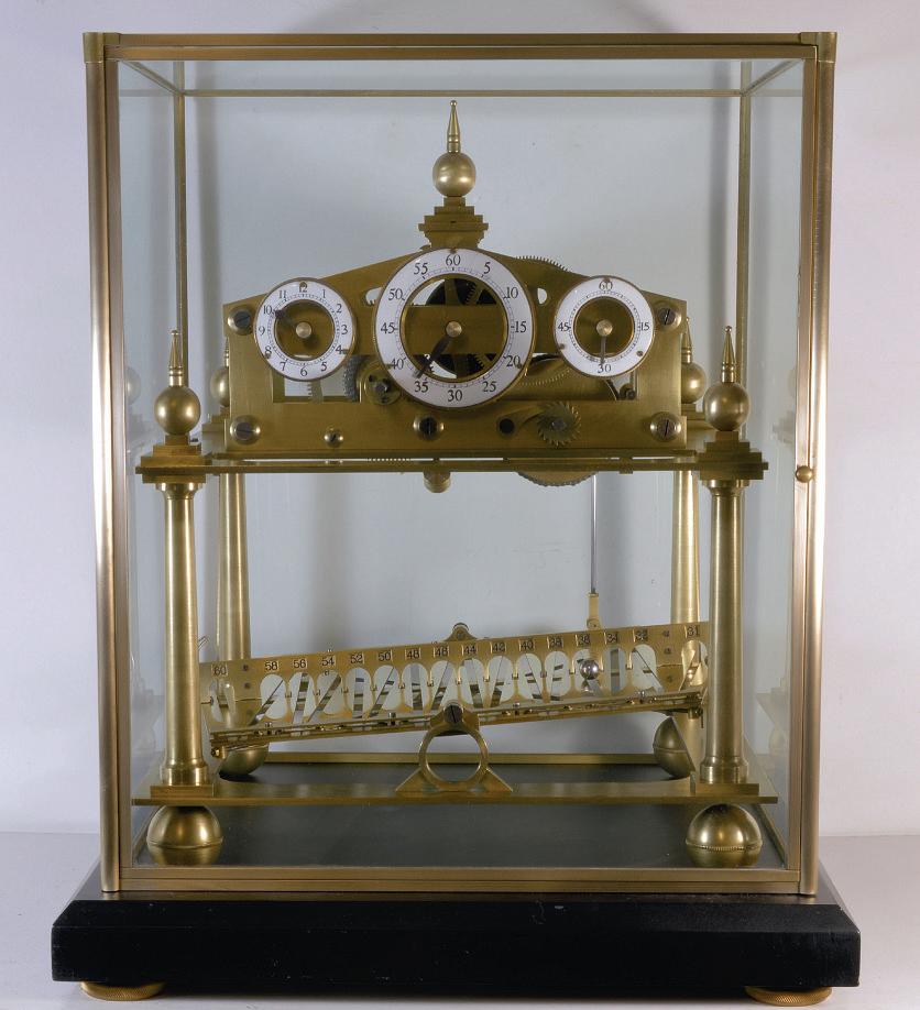
Iwas recently askedtolook at theCongreveclock shown in photo1 whichhad been recently bought in Englandon
734 ModelEngineer 31 May2024
1
ACongreveclock in itsvital glasscase.
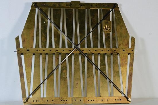
Undersideviewofthe
eBay.The clockwould appear to be possibly10or15years old. It wasnot running butwas advertised as having been workinginthe past.The new ownerhad triedtosortout theproblemsbut encountered diffcultiesand wondered if it waspossiblefor me to look at theclock,clean it andadjust themovementinorder to getit running
This is notthe frst time that Ihavebeenasked to work on theseclocksand Ihaveworked on both commercially made examples andindividualclocks made by modelengineers TheclocksI have worked on have allbeenwellmadeand theusual problems that Ihave encounteredhavemoreto do with theadjustmentand setting up of thetable than faults with themovementor components.Asmanyofthese clocks area favouritewith modelengineers, Ithought it maybeofinteresttoreaders whohaveperhaps made or are thinking of making aCongreve clocktolook at some of the problems andadjustments that need to be made in orderto getthe best outofthese most interestingofclocks.
Gravity
Most mechanical clocks rely on gravitytooperate correctly, especially pendulum clocks driven by weightsand springs. Congreve clocks arethe same only perhapsslightly more so.The Congreve clock reliesentirelyonthe forceof gravitytogiveimpetus and momentum to thesteel ball as
itzig-zagsalong itstrack on thetable
Pendulum clocks have to be leveland thependulum putinbeatinorder to operate correctly.The regularimpulse andswing of thependulum controls therelease of the escape wheel andwheel trainoveranaccurate and measured period of time.With aCongreveclock thesame principles apply, only here,the tiltingtable is theequivalent of thependulumwhich must tilt twicea minute in order to releasethe lockingwheel, letting thewheel trainoperate andthe handsmoveforward Unlikea conventional clock, thewheel trainofa Congreve clockisnot constantly driving theescapementand hands; only when thetable tiltsand thelocking wheel is released does themovementwheel train advanceand drivethe three handstogetheratthirtysecond intervals.
Thetilting andunlocking of thetable is dependenton thesteel ball consistently traversing thetable from left to rightand back againand operatingthe tablerelease levers as it does so.The movement playsnopartin drivingthe ball; theballrelies solely on theangle of thetable andgravity forits impetus.
In orderfor theballtorun continuously,the tablemustbe level. This is oneofthe prime requisites of aCongreveclock If thetable is even slightly outoflevel it will impede the travel of theball- theballwill slow down,losemomentum
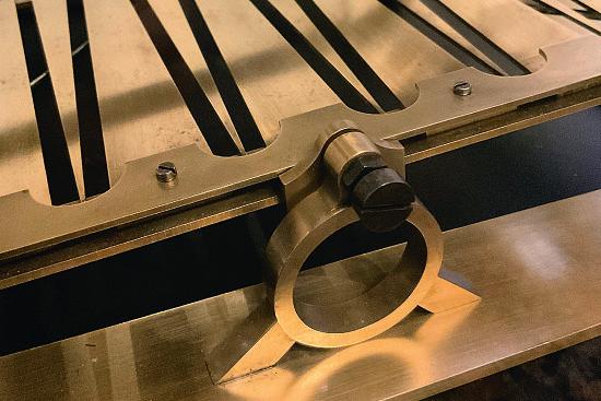
andeventually stop.The clock must also be perfectlystable andbeplacedona solid table or work surfacewhich is not pronetovibration or movement of anykind. If thetable or work surfaceissituatedon awooden or carpeted floor, anysurrounding movement caneasily upsetthe stability of theclock.Asimportant as it is forthe clocktobelevel, certainother mechanical adjustmentsmustalsobe understood andmadewhen assemblingand adjustinga Congreve clockinorder for theclock to work correctly andtohelpinpinpointing and solvingany possibleproblems that mayarise lateron. Ilist belowsomeofthe important checks andadjustments that should be made when working on aCongreveclock.These adjustmentsapplytobotha newlyconstructed clockaswell as aCongreveclock that has just been dismantled,cleaned andserviced.
Checking theflatness of thetable
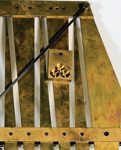
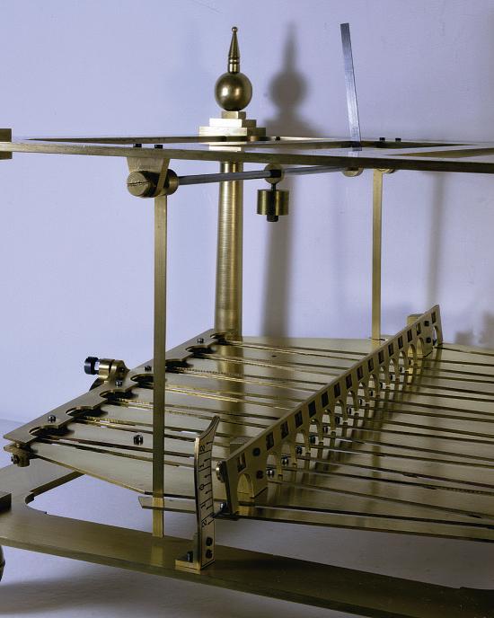
If thetiltingtable is fabricated, thesurface of thetable should be checkeddiagonally for flatnesswitha steel rule. ny curvatureofthe surfaceshould be removedbyadjusting the diagonal steel stress rods fttedonthe undersideofthe table. Thestressrodsrun in brackets andare threaded at both ends;small nuts are screwedontothe ends of the rods andthese areadjustedin ordertocompressorrelease theappropriatestressrod
untilthe surfaceofthe tableis perfectlyflat,cornertocorner. Thesurface of thetable must be flatotherwise theballwill notrun evenly alongthe track. Thediagonalstressrodsonthe undersideofa fabricated table canbeseen in photo2
Thetable should tilt freely andpositivelyinboth directions
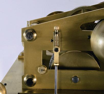
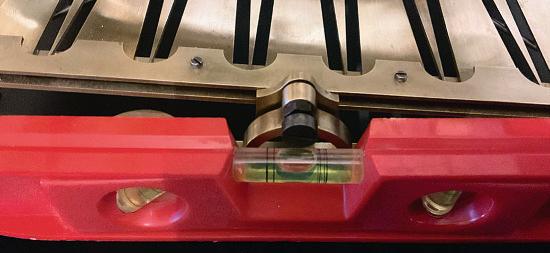
Thetable should be free, but must nothavetoo much lateral play between thetable brackets andthe tablesupport pillars Assuming thetable hasbeen checkedfor wear to thepivot screws andbearings, thepivot screws should be adjusted so thereisverylittleplayor end-shakebetween thetable brackets andthe tablesupport pillars.The pivotscrewsare adjustable andusually provided with lockingnutswhich should be tightenedwhenthe optimum position of thetable hasbeen achieved.One of thetable support brackets andpivot screws is shownin photo3
Thetable must be checkedfor balance
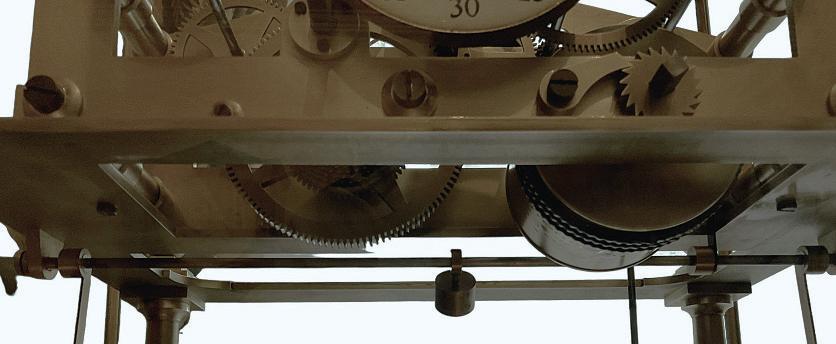
Thetable connectingrod is attached to therotating crankand thelower table bracket. Thesecomponents arepermanently attached to thetable andadd extraweight to onesideofthe table. If the tableisnot equally balanced themovementwillrequire more effort to liftone side of the tablethanthe other.
Acounterweight hasto be provided on theopposite undersideofthe tablein
735 CO NG REVE CL OC K www.model-engineer.co.uk >>
2
3
tiltingtable.Support bracketand pivotscrew
ordertobalance thetable With thecounterweight in placethe movement should liftbothsides of thetable at thesamespeed.If, when the lockingwheel is released,the movement is slower when lifting onesideofthe table than theother,the balanceof thetable should be carefully checked.
Theconnectingrod should frst be removedfromthe rotating crankand left connected to thetable.The tableshouldthenbechecked forbalance.Thismay lead to some experimentationwiththe counterweight, whichifcorrect should be suffcienttobalance both sidesofthe tableequally
Theconnectingrod assembly should also be checkedto ensure thecrank is able to

rotate freely. When assembled, andwiththe lockingwheel locked,the rotating crank andthe connectingrod must be positioned vertically and paralleltothe rear movement plateinorder forthe crankto freelyrotate.
Thetable counterweight attached to theunderside of thetable canbeseen in ,the connectingrod assembly in photo5 andthe rotating crankin photo6 In photo4 youcan seethis counterweighthas been drilledoutinorder to achievethe optimumweight.
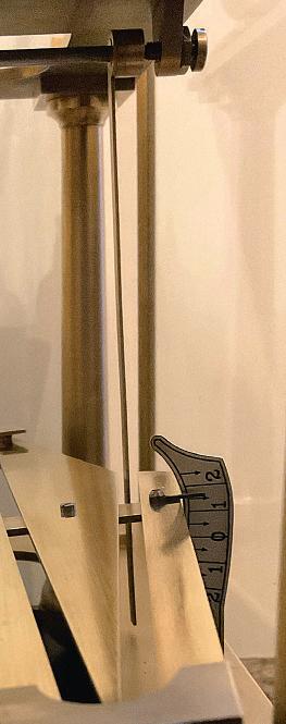
Thetable must tilt by thesameamountinboth directions In orderfor theballtotravel at thesamespeed when
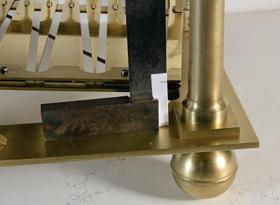
andtilt on both sidesofthe tableshouldbethe same Photograph 7 showsa small engineer’s square mountedon thebaseplate andthe position of thetop of thetilted table marked on theblade
Adjustingthe table releasework
running both left andright, thetable must tilt thesame amount in both directions.This is achieved by adjustingthe length of thetable connecting rod.
Theconnectingrod is threaded at both ends and screwedintothe rotating crankand lowerbracket;the rodshouldbescrewed in or outofthe components and adjusted untilthe tilt of the tableisfound to be equal in both directions.Thiscan be checkedwiththe useof asteel rule or by placinga smallengineer’s square on thebottomplate andmarking thedistancebetween thetop corner of thetilted tableand thebottomplate.Whenthe connectingrod is adjusted correctly,the measurements
Thetable releasework consists of apivoted steel arborrunning underthe length of thetop platewith twoadjustablebrass release levers operatinginthe ends of thetrack,a counterweight anda vertical steel locking detent whichengages with theradialpinsonthe locking wheel.The brassrelease levers should be adjusted and settohangdownwards,with theleverspositionedcarefully in themiddleofthe trackat aslight angleforward.At thesamesetting,the vertical steel lockingdetentshould be settoengagewitha pin on thelocking wheel.The counterweightshouldthenbe setatanapproximateangle of 30 degrees to horizontal.The purposeofthe counterweight is to return therelease levers andlocking detent to their original position immediately afterbeing struck by theball andthe tiltingofthe table. Theleversand counterweight should be adjusted so the lockingwheel is only allowed to make half aturnbefore beingre-arrested by thelocking detent.The counterweight must notbetoo heavyand preventthe ball from activating therelease levers,ortoo light, andslowthe return of the lockinglever
Thepositionofthe release levers in thetrack should be carefully determined to ensure they areset in themiddleof thetrack anddonot engage with thesides of thetrack whilstatrest, or whilstthe tabletilts. Photograph 8 shows thetable releaseassembly fttedtothe framebefore adjustment andbeforethe movement wasattached to thetop plate. Photograph 9 showsthe amount of desirable clearanceofone of therelease levers locatedatthe endof
736 ModelEngineer 31 May2024
4 5 6 7
Tablecounterweight.
Rotating crank, with adjustment.
Connectingrod fortiltingthe table.
Checking thepositionofthe topcornerofthe table.
components mentionedabove, theactionofthe wheel train andtable should be checked andthe frameofthe clock adjusted andlevelled.
Themovementshouldbe fully woundand thetable releaseworkchecked.Itshould be foundthatwhenthe release levers areactivated,the locking detent immediatelyreleases thelocking wheel andthe table tiltsonceonly. Afteractivation, theleversshouldimmediately return andindoing so lock the trainoncemore. Thelocking wheel should be seen to rotate
quicklyand positively with no hesitation or sluggishness. Any hesitation of thewheel train or speed in thetilting of the tableshouldbeinvestigated andthe causeremediedbefore proceedingfurther.
With respecttothisissue, it should be notedthatmost ongreve clocks arefttedwith afusée. Afusée is adevice whichevens thetorqueof themainspringasitunwinds in thebarrel. Themainspring should be ‘set up’orgiven a preloadwhenthe movement is assembled. Thepreload is notalwaysthe same on all movements, as alot depends on thesizeofspringand severalother factors, butthe preloadshouldbesuffcient so that even when thefusée is nearly unwoundand most of thelineistransferredfromthe fuséetothe barrel, thereshould still be suffcientpower to drive themovementand tilt thetable If thepreload is notsuffcient it canresultinthe movement gradually losing powerand both theturning of thelocking wheel andtiltingofthe table becoming sluggish.The preload should be checkedtosee that it is suffcientand themovement still hasenoughpower to tilt the tableasthe clockrunsdown.
Thetable should be checked in both directions andthe table should tilt with thesamespeed andbythe same amount each time
When happy with the performanceofthe table, wheel-workand releasework, theclock framecan then be levelled.
Congreve clocks arealways provided with adjustable ball feet whichare attached to fnelythreadedsteel studding, allowing even quitesmall adjustmentstobemadewhen levellingthe clock.
Initially,the frameshould be adjusted untilitisperfectly level. Aspiritlevel should be placed on thebottomplate of theframe as shownin 11 andadjustments made to the feet untilthe clockframe is level, both fronttobackand left to right.
Even if theframe is level, it does notalwaysfollowthat
737 CO NG REVE CL OC K www.model-engineer.co.uk >>
thetrack
photo10 the angleand position of the counterweightusedtore-set thelevers. Finalchecks, levellingand timekeeping Having checkedand made all theadjustments to thevarious 8 9 10 11
and
Releaselevers.
Counterweightfor resetting thelevers.
Levellingthe clock.
Ensuring therelease leveriscentral to thetrack
thetable will be levelwithinthe frame; sometimeserrors in the machiningofa componentor theassemblyofthe framecan lead to minordiscrepancies whichcan render thetable or itsfttingsslightly outoflevel with referencetothe frame. Although it is possibleto checkthe if thetable is level by placinga smallspiritlevel on thetable itself.I personally fnda betterway is to levelthe frameand then roll theballon thetable andwatch andlisten to theactionofthe ball as it runs.You canquickly both hear andsee anychanges in speed,indicatinga further adjustment needstobemade to thefeet of theclock in order to render thetable level. If this is thecase, theappropriate foot or feet arethenadjusted untilthe tableislevel andthe errorcorrected.Usually only very slight adjustmentstothe feet arenecessary in orderto make asubstantial difference to therunning of theball. When correct theballshouldbeseen to operatethe releaselevers andrun continuously at the same speed in both directions Anyunevenness in the running of theballonthe straight is usually duetothe tablenot beinglevel.However, if theballstops running or slowsafter entering aturn, theballshouldbecarefully observed as it enters theturn. Theballshouldbeseento
Ball size
enterthe turn smoothly and rotate around thefullinner circumferenceofthe turn with no reductioninspeed.The ball should notcatch on theedge at theentry of theturnand momentarily be thrown offthe track. Equally,the edge of the turn should notbetoo wide or worn,resulting in theball making contacttoo faratthe back of theturn, losing impetus andspeed
Once thetable is leveland theballisrunning correctly, increasing or decreasing the angleofthe tableisthe only variable meansofadjusting thespeed of theballand the timekeepingofthe clock. Initially,the crankadjustment screwshouldbeadjustedso thelow topcornerofthe tilted tableisroughly oneand a quarterinchfromthe surface of thebottomplate as seen in photo12.The ball canthenbe setinmotiononthe tableand arecordofthe timekeeping made.Ifthe clockislosing time,the angleshouldbe increasedtomakethe table tilt at agreater angleand increase thespeed of theball; conversely theangle should be decreasedifthe ball is running toofastand theclock gaining in time.The crankadjustment screwonlyrequiresa small amount of regulation to make a noticeable difference to thetilt of thetable andthe speed of theball.
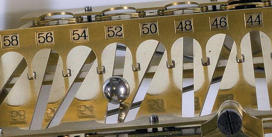
Theballonthisclock is 12mm in diameter andworks well. Thesizeand weight of theball is importantasitcan affect theoperation of thetable.If theballistoo light it canhave diffcultyinoperating thetable releaselevers; tooheavy and themovementmay require more powertoliftthe tableand slow thespeed of thelocking wheel andthe tiltingofthe table.
Lubrication
Themovementpivotsshould be oiledwitha qualitymedium gradeclock oilexcepting thoseofthe fuséearbor and thebearingsofthe barrelon thebarrelarbor,which will beneft from aslightly thicker gradeofoil. Thefusée arbor andbarrelbearingstakethe main powerofthe mainspring andwill naturally be subjectto more wear.The tablepivots andthe tworadialpinsonthe lockingwheel should also be lightly oiled. Theseare theonly itemsthatrequire lubrication. Thetable releaseleversdonot requireany lubricationand on no accountshouldany oilbe appliedtothe trackorball.
Cleaning of theballand table
Thecleanlinessofthe ball andtable is also important. Over theweeksand months of running, even if theclock is enclosed in aglass case,the tablewill attractdustwhich will transfer onto thesurface of the ball. Over aperiodoftimethis will accumulate andeventually slow therunning of theballin thetrack.The tableand ball should be regularlycleaned with alint-free cloth, preferably
everytwo or threeweeks. On no accountshouldany polishing materialsbeapplied to either thetable or ball as this couldbuild up andhave to be removedata laterdate. Thetable andballare shownin photo13
TheCongreveclock is a notoriouslypoortimekeeper andyou certainlydon’t buy or make aCongreveclock if youwantanaccurate timepiece. Theclockscan be diffcult to ad ust,one alteration invariably leadsto another, butifthe mechanism is understood,adjustedand setupcorrectly,and the clockplacedona solid and substantialflat surface, there is no reason whyitshouldnot runperfectly well. Depending on your hearing, they canbe quitenoisy in aquiet room. Theendless motion of the ball andthe noiseofthe table as it tiltsisquite noticeable They are, however, undeniably fascinatingtowatch.Likea skeleton clock, youcan seeall of themechanism in action, making it visually easy foreven thenovicetounderstandand graspthe principles employed in theclock’s construction andoperation.Theyare a wonderfulshowpiece and always of interest to those whosee them.Ifmadebyan individual modelengineer or clockmaker they arecertainly achallengingproject and incorporatea lotofcombined clockmakingand engineering skills.The work andeffort is, however, well worthwhile,the clockproviding alongstanding testamentand legacy to the skills of themaker
738 ModelEngineer 31 May2024
ME 12 13
Theangle of thetable determines thespeed of theclock.
Counting offthe seconds.
Hau li ng t he To ys -P ar t2 Hauli

Steve Goodbody takesa random walk through modelengineering.
Continuedfromp690
M.E.4743 May17

Whenweleftour colonial correspondent,he hadjustarrived home with anew trailer, six feet long andten feet wide in itsstockingedfeet, with a hinged andribbedrampat itsrearand waspreparing to convertitintosomething that wouldcomfortably haul both a traction engine with itsdriving trailerand asteam locomotive with itsattendanttrain,albeit notatthe same time
TheWindinthe Willows
To kick this episodeoff, let’s have alook at that important aspect of anytrailer -its entrance -for withouta well thoughtout entrance youwon’t be able to load your trailer andifyou can’tloaditthen youare theproud ownerof nothingmorethana fresh-air transporterwithwheels. Having lived throughthe excitement of acoupleoftornadosand severalhurricanesoverthe years, includingSuperstorm Sandy, theauthorcan categorically confrm that fresh airdoesn’t need awheeled transporter, it canhappily shift itself from AtoB withoutany help from youormeand can do so farfasterthanwecan safely drive. Trustmeonthis ( 5).
Conflictingneeds
While Igenerally trytoavoid statingthe blindingly obvious, it is asimplefactthattraction enginesand steamrailway locomotives, while sharing some basicsimilarities,are notthe same.Inessence, it allcomes down to thewheels, doesn’tit? Atractionengine likes aniceflat surface the ground is idealinall respects while arailway locomotive prefersrails andstrongly dislikes theground. Areyou with me so far? Ithought so Having piqued your interest with theseastonishing insights, let’sconsiderwhatthismeans in thecontext of theauthor’s
transportation trailer, with itsribbedand hinged ramp doublingasthe entrance gate, to pick anon-randomexample Now, if youare aweighty traction engine andwantto gain access to thebed of a transportation trailer, then what youreallydesireisa nice, smooth, solid loadingrampnone of thoseuncomfortable ribs,thank youverymuch -which is long enough to providea gentle slopetothe ground andgivethe winch- a necessary componentinthe struggleagainst gravity- a fghtingchanceofgetting the beasttothe topofthe hill withoutdestroyingitselfinthe processorstallingitselfinto submission.Let’s face it,that wouldbeembarrassing forall concerned, wouldn’t it? However, when you’re driving this contraptionalong the highway, with thegateraised in itsverticalposition, then youreally don’twanta solid wall sticking up in theair like amainsailand providing- as it would- theaerodynamic slipperiness of agardenshed andgeneratingthe unenviable fuel economyofa Chieftain

739 www.model-engineer.co.uk >>
Pa rt 12 :
35
Superstorm Sandy’saftermathprovestothe author’s youngfamily that freshair needsnohelpinmovingrapidlyfromA to B.
tank.No, that wouldbeno good at all.
Conversely,while asmooth andsolid ramp is allwelland good fora traction engine,what if youare transporting arailway locomotive?Inthatcase, in ordertosuccessfully transfer your precious cargofromtrailer to railway,anentirelydifferent item is probably needed;a bridge,which is suffciently long andsuitablystrongto span thetrailer’slowered ramp,which is gettinginthe way, andtointerconnect the trailerwiththe turntable(or traverser, or whatever loading andunloading arrangement exists at therailway destination, butI’lluse ‘turntable’ as the catch-allexample andask that youmentally modify thedetail to matchother situations) andsupport theweightofthe locomotive as it is wheeled across thechasm.However,the
troublewithbridges is that they tend to be afxedlengthand this meansthatthe trailermust be accurately positioned avery specifcdistanceawayfromthe turntableatthe start. Buthow to judgethatdistanceasyou reversethe trailertowards its destination? If thetrailer’sgate is left in itsraisedposition, then thecargo area is hiddenfrom view andthe correct distance is impossibletojudge.Ifthe gate is lowered, then it dragsalong thegroundand makesa real mess of things.
Andso, to summarise, what I ideally needed wasa nice,long, smoothramppermanently attached to thetrailer’s ribbed gate forthe traction engine,a sturdy bridge to span theramp forthe railway paraphernalia, some waytoaccurately judgethe distance behind thetrailerwhile reversing towardsthe turntableand
nothing more than theoriginal aerodynamically-ribbedgate pointing towardsthe skywhen travellingalong thehighway Andthe solutionstothese apparently conflicting goals must notconsume valuable payloadspace and, to throw anothercriterion into the overflowing mix, thetransition from railway duty to traction engine haulagetohighway motoring andvice-versamust be quickand,preferably, requirenotoolsatall to accomplish. Straightforward, eh?Hohum.
Conflictresolution
NowI must admitthatthisis thesortofchallengeI enjoy: aset of apparently conflicting goals, adecentconstraintor twoand ablank sheet of paper on whichtobegin Clearly, therampfor the traction engine wasthe frst
problemtoovercome, fornot only wasthe transportation of RubySwann amorepressing issuethanthe then-incomplete JenniferAnn,but,I reasoned, thedimensionsand details of therailway bridge would probably be dependenton theeventuallengthof Ruby Swann’s ramp and, hence, thedistanceitwould need to span.One spring morning, with sketchbook at theready, Ilowered thenew trailer’s aerodynamically idealgate to thegroundand beganto ponder theburning question; howtoconvert theribbed ramp into asmoothversion, extendingall theway to the ground when in thelowered position butleaving nothing to impede theairflowwiththe ramp raised
While Icould certainlymake aremovable ramp,stored within thetrailer alongsidethe
740 ModelEngineer 31 May2024
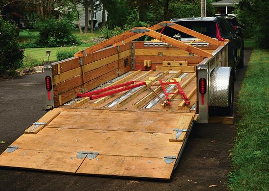
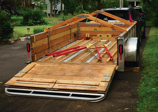
Theplywood ramp attached to thereargate, folded andready fordeployment.
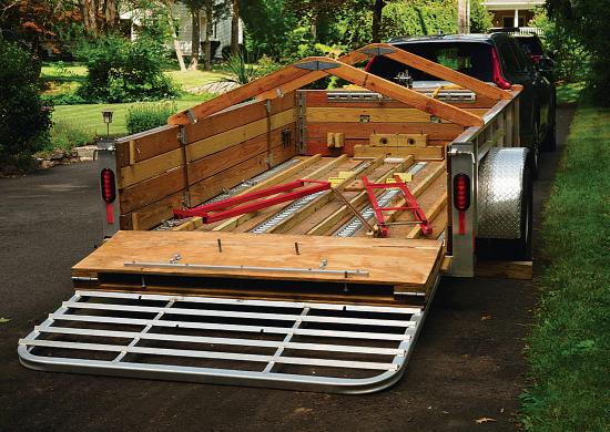
With theside-by-sidelowestportionsunhinged, therampmeetsthe ground and gi es exibilit tocopewith ne ens rfaces.
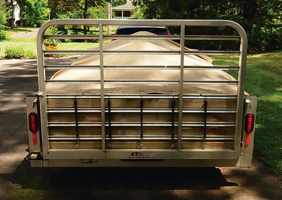
With thegateraised, thefoldedrampenclosesthe rear of thetrailerwhile leaving itsaerodynamicsunaffected.
36 38 37 39
ith thefrstpart nfolded, therampdoesnot itereach thegro nd.


 MARTIN EVANS Editor
DIANE CARNEY Assistant Editor


