
4 minute read
A 3D printed XY table
Adrian Rawson made a micrometer adjustable work table for a measuring microscope
Having recently completed the construction of an electronic measuring microscope based on a Raspberry Pi coupled to an HQ camera, I realised how useful a small micrometer adjustable XY table would be to make ‘accurate’ measurements, photo 1
I looked at buying one and found some nice examples for around £100
This led me on to thinking about making one out of steel or aluminium, more as an interesting project than a money saver Whilst contemplating the design and the milling involved, I wondered if a satisfactory result might be achieved by 3D printing one in plastic
My frst uestions were would the slides be smooth enough and how could I make them adjustable? My second concern was ac uiring suitable micrometer heads that I could design around Afer a bit of contemplation and a search on the internet, revealing some suitable 13mm micrometer screw heads for about £7 each, photo 2, I decided it was worth a shot

The micrometer shown is graduated to 0.01mm but given other vagaries of the construction an accuracy of +/- 0 01mm should be achievable which in English is better than a thousandth of an inch, possibly not laboratory standard but good enough for a bit of horology.

Once the micrometer heads arrived, I took some measurements and set about creating a CAD design using OpenScad, which was used to render many of this article’s images
Afer a couple of false starts came up with a slide adjustment mechanism based on a fe ible do etail and a spring
Return Which Obviated The Necessity To Grip The Micrometer Heads Plunger
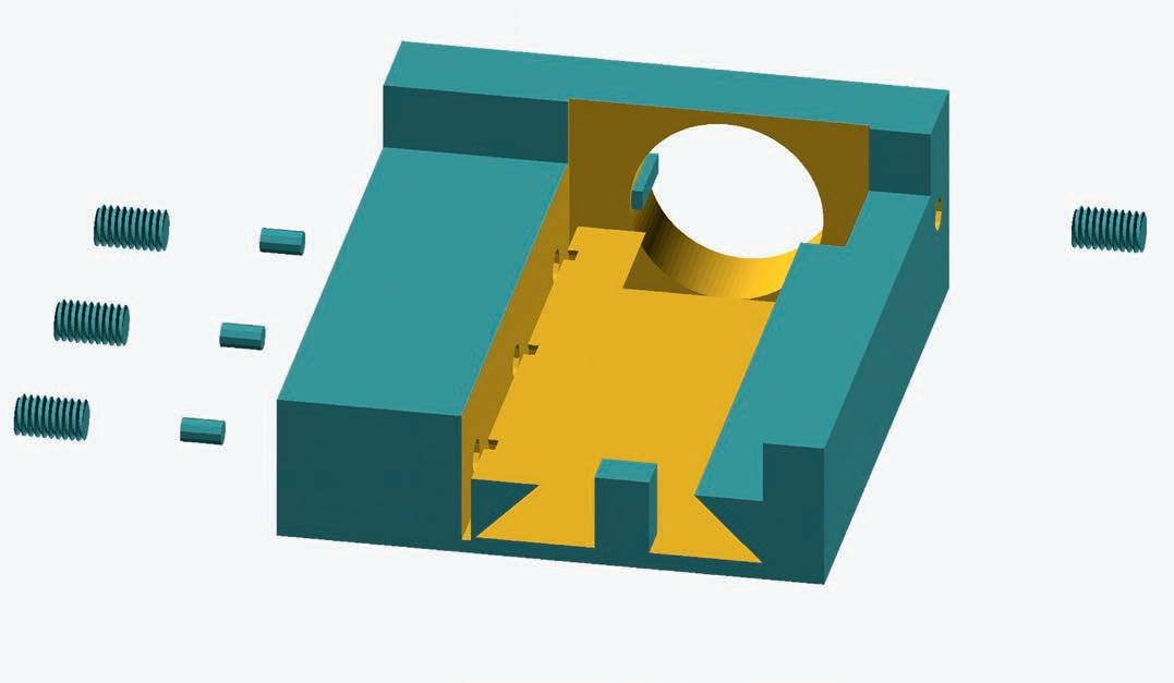
The bottom slide, photo 3, shows the fe ible do etail which is barely attached allowing it to be fe ed inwards by the grub screws
The top slide, photo 4, has a slot between the dovetails to accommodate the return spring and an insertable plug to retain the spring once assembled components prior to assembly
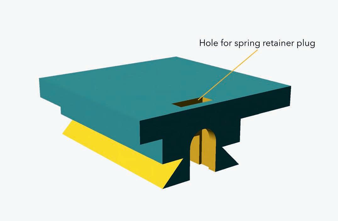
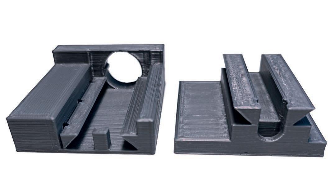
Photograph 6 is a CAD render of the plastic parts re uired for construction The orientation shown should print without the need for any support material. The secret is to use the fnest slices that the printer will allow

Once the components are printed the ft of the micrometers should be checked and the 14mm location holes cleaned up if necessary In my case they were a snug ft straight o the printer ow the slides can be checked for ft If they don’t slide together check for bits of spurious plastic and remove them If they slide together completely with a bit of encouragement, then they should ease up afer a few back and forth movements and become super smooth afer a coat of PTF spray photo 7 This is magic stu as it flls in the undulations in the plastic and leaves a coating of PTF nly spray the sliding surfaces as other surfaces will later be glued
It’s now a good time to tap the 3mm holes for the grub screws, photo 8. As I didn’t have a plug tap available, I tapped the adjustment holes until the taps taper reached the fe ible do etail then flled the gaps with short plugs of 1.75 PLA plastic flament. This scheme worked well with the 5mm long grub screws I had available The grub screw used as a retainer for the micrometer head can be tapped right through.

Provided everything slides freely it’s time to ft the springs photo 9 I used ballpoint pen springs, but the design allows for something a bit larger in diameter if necessary The springs I used had to be stretched a bit to ensure su cient tra el. This is a bit fddly but the aim is to keep the table under tension once the spring retaining plug is in place. The spring retaining plugs, as printed, will most likely need a bit of fling to ensure a good friction ft.
As the X and Y slides need to operate in their respective axes they must be stuck together at right-angles to each other I was planning to use superglue but, in the end, used thin double sided tape which proved perfect for the job and o ered the opportunity of disassembly should mistakes be made Consider the fnal orientation of the micrometers when sticking the two slides together.

Now the slide assembly can be stuck to the base Consider access to the mount’s screw holes when completing this step Fi the slide assembly o centre to satisfy this
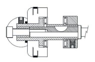
Finally the micrometers can be attached The design accommodates the notched mounting ring that came with the micrometers There is a printed location point at one side of the mounting hole The other notch accepts the grub screw, photo

To tune out any sideways defection in the X and Y tables adjust the grub screws Cut some pieces of PLA flament about mm long and drop them in the three adjustment holes on the f ed slides ow insert the grub screws and wind them in until resistance is felt Whilst moving the top slide back and forth tighten the grub screws one at a time until the slide starts to bind (don’t over tighten as this may strip the plastic thread then back o ensuring that it continues to move freely under the tension of the return spring
The return spring’s sti ness and length will tend to govern the optimum travel of the table, but if this centres on the half way point (6 5mm) it should prove satisfactory
I have used the table to measure various sub millimetre items and it has proven its worth, particularly considering its low cost
The ST fles re uired for construction are available for download on my web site www ahrprojects co uk


