


Risetothechallenge of producingaccuratelymilledfixings. Rise to the challenge producing accurately milled fixings.


Risetothechallenge of producingaccuratelymilledfixings. Rise to the challenge producing accurately milled fixings.


Ausefulbeginnersproject introducing inners projectintr awide range of techniques.


RichardLofing needed afixed steady fora Myford ML10.

Bigorsmall, Roger Froud’sdesignhelps keepallcans of paintfresh.
MAKE PAUL TINEY’SSHEETMETALROLLERS IMPROVEMENTS FORYOURBENCHMILLING MACHINE. SUPPORTINGANDSTEADYING. FINISHINGTOUCHESFORTHE TOOL AND CUTTER GRINDER. USING AMICROMILLINGMACHINE. REPAIRING AMACHINELATHE. EXPERIENCES WITH ADENFORD CNC LATHE. MMEX2024 –THE TALKSPROGRAMME. PLUS ALL YOUR
Getmoreout of your workshop with MEW





EDITORIAL
Editor: Neil Wyatt
Designer: Druck Media Pvt. Ltd.
Publisher: Steve O’Hara
By post: Model Engineers’ Workshop, MortonsMedia Group,Media Centre, Morton Way, Horncastle,LincsLN9 6JR
Tel: 01507529589 Fax: 01507371006
Email: meweditor@mortons.co.uk
©2024Mortons Media ISSN0033-8923
CUSTOMER SERVICES
General Queries &BackIssues
01507529529
Monday-Friday: 8.30-5pm Answerphone24hr
ADVERTISING
Group Head of Investment
Model &Tractor Publications
Mason Ponti
Email: mason@talk-media.uk
Tel: 01732920499
Investment Manager
KarenDavies
Email: karen@talk-media.uk Tel: 01732448144
Talk Media,The Granary, DownsCourt, Yalding Hill, Yalding, Kent ME186AL
PUBLISHING
Salesand Distribution Manager: Carl Smith
Marketing Manager: CharlottePark
Commercial Director: Nigel Hole
Publishing Director: DanSavage
Published by: MortonsMedia Group, Media Centre, Morton Way, Horncastle,LincsLN9 6JR
SUBSCRIPTION
Full subscriptionrates (but see page 54 foroffer): (12months12issues, inc post andpacking) –UK £70.20.Exportrates arealsoavailable –see page 46 formoredetails.UKsubscriptionsare zeroratedfor thepurpose of Value Added Tax. Enquiries: subscriptions@mortons.co.uk
PRINT ANDDISTRIBUTIONS
Printed by:Acorn WebOffsetLtd., W. Yorkshire Distribution by:Seymour DistributionLimited, 2EastPoultry Avenue, London, EC1A 9PT TelNo: 02074294000
EDITORIALCONTRIBUTIONS
Accepted photographsand articles will be paid foruponpublication.Items we cannot usewillbereturned if accompanied by astamped addressed envelope, andrecorded deliverymustclearly statesoand enclosesuffcient postage. In commonwithpractice on other periodicals,all materialissent or returned at thecontributors ownrisk and neither ModelEngineers’WorkshopMagazine theeditor,the staffnor MortonsMedia Ltdcan be heldresponsible forlossordamage, howsoevercaused. Theopinions expressed in MEWare notnecessarilythose of theeditor or staff. This periodicalmust not,without thewritten consent of thepublishersfrstbeing given, be lent,sold, hired outorotherwise disposed of in amutilated conditionor, in anyunauthorised coverby wayoftrade or annexedtooraspartofany publication or advertising, literary or pictorialmatterwhatsoever.
This issuewas published on 19 June 2024 Thenextissuewillbeonsale19July2024

I’mgrateful to reader,Chris Delger, who haskindly sent me acataloguefor the 1954 Model Engineer Exhibition. Ihaveonlyhad it aday or two, and running to ninetysix pages plus covers I’veonly had the chance to have aquick skim, but thereare many interesting snippets. The exhibition wasopened by the Prince of the Netherlands, PrinceBernhard of Lippe-Biesterfeld,pictured in RAF uniform. It’sfascinatingtolook up his Wikipedia page.


Naturally the most interesting of the competition classes was‘Tools and Workshop Appliances’.Entrants were notafraid to tacklechallenging projects, Iwill list them in full: ATurpin type universal dividinghead;0-1 inch micrometer; compound slide rest for adrillingmachine; Duplex engraver, 2¼”instrument lathe, watchmaker’s combinationlathe and drillingmachine (see the phopto); pressuregauge calibrator and tester modifed ME jigsaw machine; 1½”centrelathe; anda screwcutting dial indicator
Another interesting competition wasthe Model EngineersStudent’s Cup, amassing ahealthytwenty-seven entries. Around half of these ‘setsof engineer’stools’ madeby, presumably, apprentices at Electro-Hydraulics Ltd. The internet shows the company were manufacturersofaircraf landing gear,forklif trucksand hydraulic mining equipment, fromatleast 1943 to 1964.Other tooling related entries aremoreunspecifed engineers’ tools and asurfacegaugeand scriber.There were also tools by A/T C. Hartlandof

Sunderland, IassumeA/T is air trainee, an RAF apprentice.
This is probably agood point to remindreaderstomakesubmissions for the Stevenson Trophy, head to tinyurl. com/mr3b2z6d fordetails or followthe QR code.
The programme carries plenty of advertising, astandardMyfordML7 lathe, then only an eight-year-old design,with built in drivewas £485s. Thatwould be the equivalent of just over £1,100 in 2024, whichseems avery good deal. My attentionwas also caught by an advert headed ‘refrigeration forthe home constructor’
Ishall try and remember to bring the programme alongtoMMEX in October, if anyone is interested in takingalook.
Neil Wyatt









9 Thread Milling in the Workshop
Bob Reevetacklesa challenging machining operation, this article supports atalk to be given at MMEX in October
15 AFixed Steady fora Myford ML10
RichardLofing made this accessory in order to machine areplacement partfor avintage tractor
21 ATurntableWeight
This beginner’sprojectfromNeil Wyattuses various machining techniques such as taper turning and knurling.
28 Micro-Milling –Part 6
In the fnal instalmentofthis series, Mike Tilbyputs his micro-milling machine to work cuttingblades for miniatureturbine wheels.
32 Getting To Love My DenfordNovaturn
Mick Knightsmakes aset of toolholdersfor hisNovaturn CNC lathe.
38 From the Archives
This month we revisit avicerenovation from 2001
40 The PottyEngineering Cutter Grinder
Stewart Hart completes this excellent ‘quick and easy’ design grinder for restoring blunted milling cutters.

47 The Midlands Model Engineering Exhibition
Here’s the timetable forthe MEW Talks Programme at this October’s MMEX exhibition.
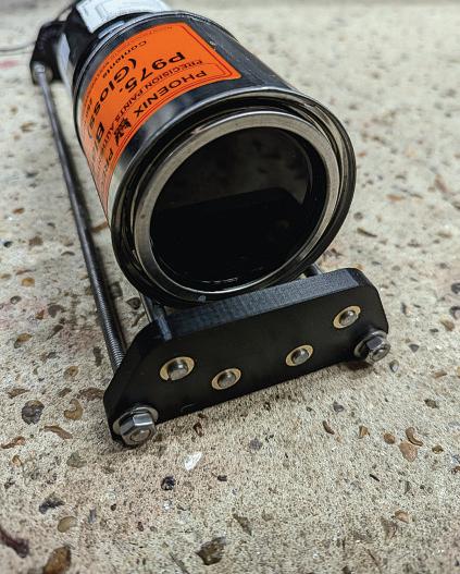
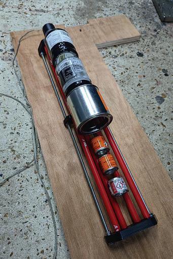
50 AFlexible Paint Can Turner Ahandy accessory foranyone who strivestoachieve the bestpaint fnishes, from Roger Froud.
54 Getting the most out of your Brushless Mill -Part4
Jason Ballamyhas anumber of useful modifcations to his SIEGSX2.7 mill.
60 Beginner’sWorkshop
Geometer looksand ways of supporting and steadying workpieces to makehandwork easier.
61 ASheetMetal Rolling Machine
Paul Tineymakes astraightforward but efect setofbench rolls.


In our next issue Jacques Maurel explainshow to carry out Vickershardness testing.
3 On theEditor ’s Bench
The Editor studies the programmefor aseventy year old exhibition.
36 Readers’ Tips
Our winner thismonth found away to stop hislathe coolant degrading. Send your tips to meweditor@mortons.co.uk, you could win aprize.
48 Scribe ALine
In this month’s postbag morebandsawmodifcationsand a mystery steam engine. We arealwayskeen tohear from you–send theeditor your thoughts at meweditor@mortons.co.uk.
58 On theWire
This month’s round up of news from theworldofhobby and full-sizeengineering looks at anew book on Digital Command and Control.
64 Readers’Classifieds
This month’s collection of readers’for sale andwantedadverts.
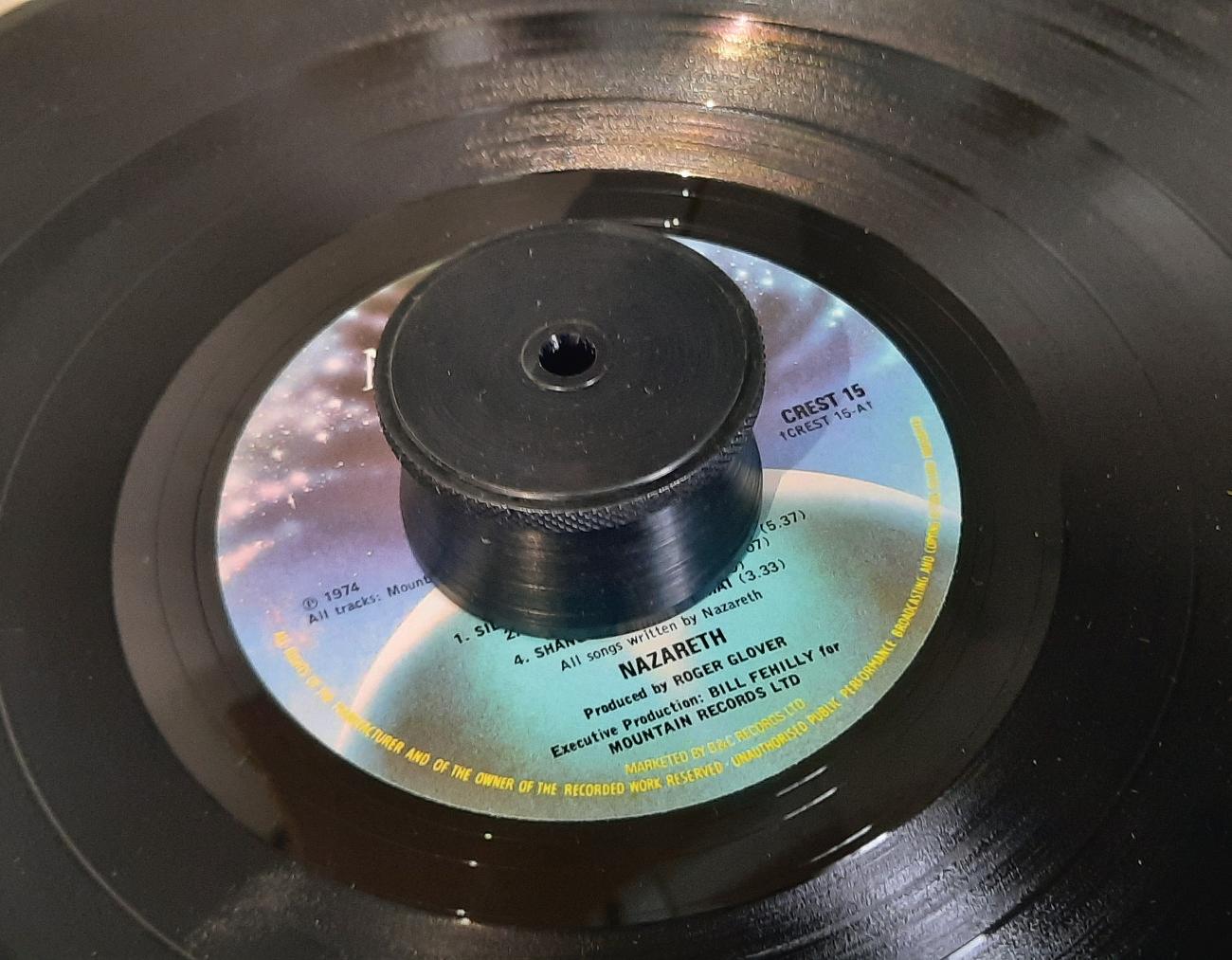
Ourcover featuresa simple record turntable weight,anideal beginner’s project that involves agood range of machiningoperationsaswellas chemical blacking. Seemoredetails on page 21


See the videos forJason Ballamy’s Brushless Millseries: https://www.model-engineer.co.uk/forums/topic/getting-the-mostfrom-you-brushless-mill/
Or search the forum for‘gettingthe most’
Hottopics on the foruminclude:
Silicon bronzeMIG brazing Started by Speedy Builder5
An old technique brought up to date.
Towardsabetterlooking angle plate Started by MikeK
It’snot just about looks, abetter fnish aids accurate, secure clamping.




EW Stringer Lathe Spindle Speed StartedbyJamesAlford. What sorts of speeds areappropriate foranvintage lathewith aspindle running in cast iron?
As well as plenty of engineering and hobbyrelated discussion, we arehappyfor forum memberstouse it to share advice and support. Come and join us –it’sfreetoall readers!

































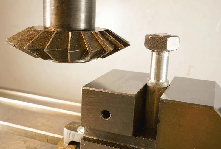
Bob Reeveinvestigates into the practicalityofthreadmillingusingCNC and various types of cutter.
Most Model Engineersstart making screw threads using taps and dies, then progress to turned threads made on alathe. But there arealternatives, some more practical than others. ForexampleI remember seeing aleadscrew from a large planing machine exhibited in the Birmingham Museum of Scienceand Industry when it waslocated in Newall St.Istood in aweofthis exhibit, tens of feet long, severalinches in diameter and allmade by hand.
Alternativethread making techniques, notsodemanding on manual skills, might include thread rolling and thread whirling. Ihavesome long high tensile bolts with Whitworth threads which Iwatched being rolled before carrying them back tomy workshop foruse on the milling table. Then therewerethe whirledthreads I encountered as part of the MultiRole CombatAircraf asitwas then wing sweep mechanism. Whirled threads involvethe cutterrotating around the work piece. Aprocess used wherelong or very precise threads arerequired which might nothavethe commonveeform thread. In the MRCA these were essentially very robust and compact concentric, telescopic ballscrews. Their function wastoreconfgurethe wings in the transition from subsonic to supersonic ight and vice-versa. The loads were enormous, and the precision wassuperb.Tomyeyes, aminor triumph of engineering.
In amoredowntoearth moment at an SMEE zoom meeting of the Digital Group,the co-ordinator,Brian Neale asked if anyone had tried threadmilling No one had, but it sounded likean interesting challenge andthe Digital Group might have both the necessary

CNC mills and the programmingskills to do it. Challenge accepted! Ialready had the requisite CNC milling machine which has appeared in these pages before Photograph1 shows my X3 which wasconverted toCNC manyyears ago.This machine is basically athree-axis machine to which has been added a4th rotary axis. Note thatthereisnofacility for tilting the head on this machine.
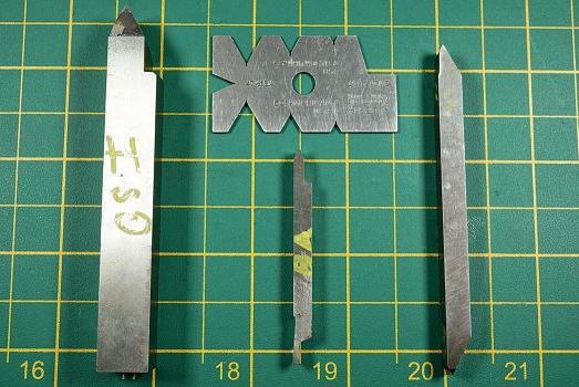
First on the list of problems to be addressed wasthe question of the helix angle. This has alwayspuzzled me because thread cutting in the lathe appearstotakenoaccount of the change in thread geometry causedbythe helix angle of the thread. Thetraditional gauge in photo 2 is used to grind the tools shown belowit. Ihavenever come across anyone tilting the toolbythe helix angle to retain the exact threadformintended. The efect is small, becausethe helix angle is small. However, at this stage Idecided nottopursue this in detail, pending discussions with fellowSMEE memberswho might hopefully be more knowledgeable on the subject.
Idecided to putsomeboundaries on the threads thatI might wish toexplore. Starting with metric threads as being the most common butperhaps notto model engineers .I did notanticipate millingvery small diameterssince the
workpiecewas unlikely to be su ciently rigid to withstand afull-frontal attack by amilling cutter.The 60° thread form presentsaneasyangle to generateand the pitch increment of 0.5mmfor many of the larger sizesreduced the number of variants.
My second choicewas the Whitworth thread form mainly becauseitisa relatively coarse thread which wasin common use before metrication and thereare quite afew deployedinthe venerable machine tools thatoccupy my workshop.Added to which they arebecoming increasingly di cult to obtain and can be disproportionally moreexpensive
Ialwaysintended to start with external threads on the groundsthatit waseasier to see whatI wasdoing and therewas less likelihood of crashing into the workpieceatthe beginning and ends of the cut.
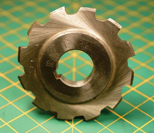
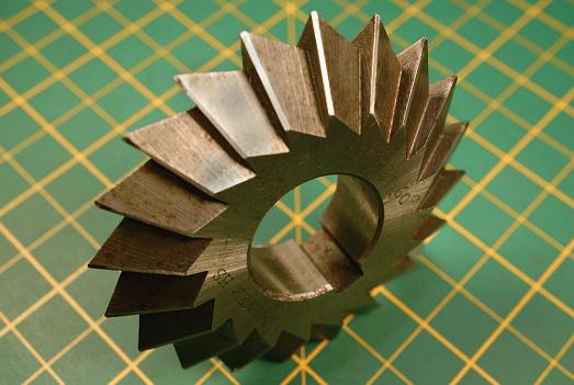
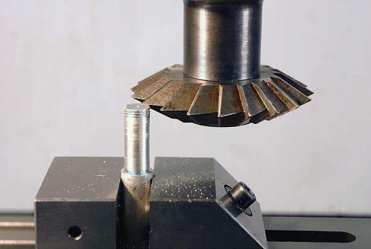
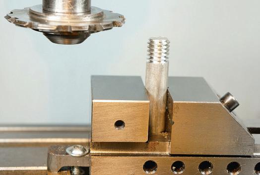
The next taskwas to explorewhat tooling wascommerciallyavailable. I’m notaversetomaking my owntools, but Iusually optfor the commercial option unless it gets prohibitively expensive or simply unavailable. Fortunately that turned out nottobethe case. Istarted with cuttersfor metric external threads. Firstupwas apreowned cutter with twoangled cutting facesmeeting at the required 60° , photo 3 This is nota full form cutter and will notround either the thread rootsorthe tips. Thatsaid, it wasmine in exchange forthree crispyfvers!Its conditionwas good,and it had notdone much work so didn’t need sharpening. The next step wasmoreambitious; afullform cutter fora 12tpi Whitworth thread. “Full form”because it would cut the correct threadform, complete with radiused tips androots,but only for 12tpi, photo 4

Three morecrispy fverswereinvested. At which point Imomentarily re ected on the loss of the oppy, dog-eared and dirty old fvers. Another part of our historic heritage lost to the plastic age?
Photographing the fullform capability of this cutter wassomething of a challengebut photo 5 shows the details. With atip radius forthe thread root and twosmaller radii on the internal corners which will provide aradius on each side of thethread crest.
It shouldbeobvious thatthe cutters detailed so farwerenot suited to internal threads unless of exceptionally large diameter . My choicefor internal threading needed to be much smallerin diameter and would thereforehaveto run at much higher speeds. These turned out to be carbide tools with three ground threads so as to generatea full thread form. Needless to saythree fverswould notcut it this time!
And so to the next question –to program or nottoprogram Asu ciently comprehensiveCAM package would do the necessary,given su cient information to defne the thread details and its location. Essentiallyitisan exercise in spiral pocket milling. Ihad used asimilar strategy to this formilling the ports in an inletmanifold foran automotiveapplication. Thatexercise was done using the BobCAD CAM package, which wasvery successful, ref. 1. The downside wasthatthe CAM program produced enormous fles which took a long time to execute. Thistime Ielected to manually programthe threadcutting on the grounds thatall thatwas required wasaspiral path defned by the diameter, pitch and depth from agivenstart point. Hopefully Imight encourage afew budding programmerstohavea go However, Iwouldpoint out thatinmy experiencesuccessful programs are rarely created in ablinding ash of inspiration. More ofen it requires a series of incremental improvements until success is achieved. Even then it is not perfect! To thatend Ihaveset out some of the stages thateventuallyled to a successful conclusion.
Iuse Mach 3for theprogramming. This, or the later Mach 4, arefreefor the demonstration version, so making astart is relatively painless. Inaddition, the program simulatorsincluded are very usable forprogram development.
The budding programmer does noteven need aCNC machine!
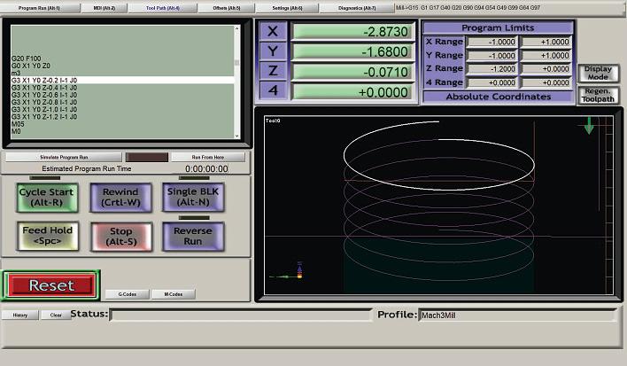
Milling circles or arcs can be abit tricky, especially sincecomplete circles linked by ahelical path were required forthis program. The G 2 clockwise and G anticlockwise commandsfor circular interpolation arecomplicated by the options to use the Radius Formatarc with A, B, Cand Raswell as theusual X, Y, Z wordsoralternatively,the CentreFormat arcrequiring all those, plus I, J, and K. So, by wayofa start Iprogrammed the centre formatarc as follows:
%Spiral 1
G20F100
G0 X1 Y0 Z0
M3
G3 X1 Y0 Z-0.2I-1 J0
G3 X1 Y0 Z-0.4I-1 J0
G3 X1 Y0 Z-0.6I-1 J0
G3 X1 Y0 Z-0.8I-1 J0
G3 X1 Y0 Z-1.0I-1 J0
G3 X1 Y0 Z-1.2 I-1J0
M05
M0
This has one line foreach complete circle andapitch of 0.2mm. Readers
who wish to type it into Mach 3, should fnd thatitdoes indeed produceaspiral cutter path but for this trial no cutter is needed. Runthe program o ine. As alwaysreaders should ensurethis is suitable for their CNC machine and is within their competencetouse it, fig. . This is asnapshotofthe program running and the frst turn of the thread is highlighted; the remaining threads maybejust visible “ghosted” below. Iwas concerned thatMach3 will only interpolate in oneplane parallel to anytwo of the axes and this program appearstorequireinterpolation involving three axes.However,afer a bit of thought, Iconcluded thatthere wasnointerpolationrequired forthe Z axes. As farasMach 3isconcerned this is just alinear movement along the Z axis.
Those who typed in the program as written and gotittorun mighthave spotted my deliberatemistake–itisa lef-hand thread!
Therewas afurther disadvantage in the centreformat arc– it wasnot

obvious whatthe radius of the thread would be.
Jumping afew iterations, my fourth attemptwas achange of horses to the radius formatand aright-hand thread. I have also included amorecomprehensive initiation stringtoensurethe mill is set correctly forthe start of the program. This is still aspiral development program to be run without acutter and o ine,but the previous caveat still applies.
%Spiral 4
G15G17 G21 G40 G49G50 G69G80 G90
%G15 CARTESIAN CO-ORDS
%G17 XY PLANE
%G21 MILLIMETRES
%G40 CANCEL CUTTERRADIUSCOMP
%G49CANCEL TOOL LENGTH OFFSET
%G50 RESET ALL SCALE FACTORS TO UNITY
%G69 CANCEL CO-ORD SYSTEM ROTATION
%G80 CANCEL MOTION MODE
%G90 ABSOLUTE DISTANCE MODE
%Set workpiecevertical, centreatx=0, y=0
G0 Z25
M3
M6 T10 S500
F100
G0 X-5Y0Z0
M3
G2 X5 Y0 Z-0.5R5
G2 X-5Y0Z-1 R5
G2 X5 Y0 Z-1.5 R5
G2 X-5Y0Z-2 R5
G2 X5 Y0 Z-2.5 R5
G2 X-5Y0Z-3 R5
G1 X-8
G0 Z0
M30
The radius wasnow obvious, andthe program created aright-hand thread
as it should. What wasnot so obvious wasthatthereare nowtwo lines for acomplete circle and the pitch of 1mm is splitbetween those twolines. Apparently,this is amoreaccurateway of programmingacompletecircle.
The program wasmoresuccessful than Iexpected andwith the addition of corrections forthe cutter diameter it wasused to cut a10mm dia. external thread with 1mmpitch, photo 6 However, the useofsuch alarge cutter to cut such afne thread did seem alittle disproportionate.
The thread wasnot to the correct depth at this stage. Thatrefnement was to follow, and Ialso increased the pitch to amoreproportionate 1.5mm
With the spiral cutter path working properly,mynextstep wastoutilise some of the moreadvanced features of Mach 3, starting with parameters. I found this featuremost usefulwhen I wasprogramming the bevelgearsin ref2 which were defned by just afew parameters.
Iwas once told in amaths lesson that Aparameter wasasort of fxed variable – Ididn’t fnd thatatall helpful! The parametersused hereare numeric descriptions of the specifc thread that wastobecut e.g. diameter,pitch and length.The real advantage beingthat the information relating to the current thread can all be grouped together at one locationwithin the program; easyto locate and easytochange.
Parametershavesome rules associated with them. Theymust be preceded by the hash symbol #followed by areal number integer e.g. #41=10 sets a10mm dia. thread. Up to 10,320 parametersare allowedbut numbers
5 to 52 arereserved forspecifc machine functions. The following programhas fveparametersdefned, but three of them 2, are notused at this stage, theyanticipate further developments. In the interests of space, the annotationofthe initiation string G 5 to G has been omitted sinceitduplicates the previous program. #41isset to 10mm forthe workpiece diameter,and the cutter diameter is setat76.81mm by #45. Thereare also workpieceand cutter setting instructions. Formanipulating parameterssquarebracketsare normally used e.g. [#41*#24]*[1/2]. calculates the distance from the spindle c/l to the workpiecec/l.
This time the program could cut metal, but notmuch!Asyet therewas no incremental depth facility and the number of completed threads wasfxed at three. The programwas no longer gender neutral as were the “Spiral” programs. It wasthen specifcally for external threads.
%Threadmill External 1
G15G17 G21 G40 G49G50 G69 G80 G90 cancelAngle rollover: General Confg..
%Set workpiecevertical, centreatx=0, y=0
%Use 60 deg.Inc. cutter.
%Set centreline of cutter at top of workpieceZ=0
Thread diameter
2 .5 Pitch no. of complete threads
. Thread depth
5 7 . cutter dia.
G0 Z25
F100
G X 5 /2 5 - Lef of C/L 5mm clear
G0 Z0
M3
G1 X[[[#41+#45]*[1/2]]*-1] Y0
G2 X[[[#41+#45]*[1/2]]*1]Y0Z[#42*-0.5]
R[[#41]*[1/2]]
G2 X[[[#41+#45]*[1/2]]*-1] Y0 Z[#42*-1.0]
R[[#41]*[1/2]]
G2 X[[[#41+#45]*[1/2]]*1]Y0Z[#42*-1.5]
R[[#41]*[1/2]]
G2 X[[[#41+#45]*[1/2]]*-1] Y0 Z[#42*-2.0]
R[[#41]*[1/2]]
G2 X[[[#41+#45]*[1/2]]*1] Y0 Z[#42*-2.5]
R[[#41]*[1/2]]
G2 X[[[#41+#45]*[1/2]]*-1]Y0Z[#42*-3.0]
R[[#41]*[1/2]]
G1 X[[[[#41+#45]*[1/2]]+5]*-1]Y0
G0 Z25
M05
M0
Another useful featureofthe parametersavailableinMach 3was that theycould be usedastallycounters. In this case the number of threads to be cut. The tally count wasincremented automatically within the program.#53 wasused to track the totallength of thread, incrementing by half the pitch for each half-turn of threadcut.
Subroutines were also incorporated forparts of the program whichwere repeatedfrequently.Inthis case the semi-circular motions andZmovement used to cut asinglethread.A subroutine could be repeatedasmany
times as necessary.Theycomprise adiscretesection of code, usually located afer the end of the program and starting with O capital letter O and an identifcation number in this case 100.The subroutine is called from within the program by the M98 commandwhich alsoindicates which subroutine it is sincetheremay be several, and howmanytimes it will be called by Q[#43].Using aparameter forthis made it easytochange the program to adiferent thread.
%Threadmill External 3
G15G17 G21 G40G49 G50G69 G80G90 cancelAngle rollover: general confg
%Set workpeicevertical, centreatx=0, y=0
%Use 60deg inccutter
%Set centreline of cutter Vattop of workpeiceZ=0
Thread outside diameter
2 .5 Pitch
no. of complete threads
. Thread depth
5 7 . cutter dia
%Calculate intermediates
5 - 5 /2 LefOD position on Xaxis
5 5 /2 Right OD position on Xaxis
#52= [[#41+#45]*[1/2]] radius forspindle cutter
5 2/2 Length of thread counter
F100
G0 Z25
G X 5 -5 LefofC/L 5mm clear
G0 Z0
M3
G X 5 Touching workpeice
M98 P100 Q[#43]
G0 X[[[[#41+#45]*[1/2]]+5]*-1] Y0
G0 Z0
M05
M30
O Thread Cut
G2 X 5 - 5 R 5
#53=[#53+[#42/2]]
G2 X#50 Y0 Z[-1*#53]R#51
#53=[#53+[#42/2]]
M99
The last refnement to the program might well be considered the tricky bit. This is another subroutine, this time to deal with getting the depthofthread required in three steps. Iconsidered this necessary since forcutting fne threads, the workpiecemay nothavebeen su ciently rigid to cut it in one pass. The unfortunate consequencewas thatitled to nested sub routines. In this case the number of threads subroutine is within the thread depth routine. However, it wasimportant thatboth subroutines were defned at the end of the program. Although it is permitted to call asubroutine fromwithin another subroutine it is notpermitted to defne asubroutine within another subroutine. Thatroute led to some unpredictable and unwanted actions.Guesshow I found out!
%Thread Mill External 4.2 M10
G15G17 G21 G40G49 G50G69 G80 G90
Thread outside diameter
2 .5 Pitch
no. of complete threads
. Thread depth
5 7 . cutter diameter
%Calculate intermediates
52 5 /2 radiusfor workpiece cutter
5 - 52 LefODpositiononX axis
5 52 Right OD positiononX axis
5 Thread depth
F200
G0 Z25
G X 5 -5
G0 Z0
M3
LefofC/L 5mm clear
M P Start of depth control
G0 Z0
M05

M30
O cut depth
G X 5 Touching workpiece
5 2/2 Current length of thread counter
52 52- . 55 radius forspindle cutter
#51=#52
#50=[-1*#52]
M98 P100 Q[#43]
52 52- . 55 radius for spindle cutter
5 - 52 LefODposition on Xaxis
5 52 RightODposition on Xaxis
G0 X[#50-5] Y0
G0 Z0
#53=0
M99
O One Complete ThreadCut
G2 X 5 - 5 R 5
#53=[#53+[#42/2]]
G2 X#50 Y0 Z[-1*#53]R#51
#53=[#53+[#42/2]]
M99
Note thatthe newsubroutine O101 has the original subroutine O embedded within it. The tricky bit wasto ensurethatthe parametersthatneeded

to be updated, were updated at the correct pointi.e.beforethe beginning of the subroutine, or afer the end
Because the threadsproduced were notfully formed, therewas no radius on the crest, just as they would be if turned on the lathe. The remedy wasa fne fle or run the correct size splitdie down it –just between fngersand thumb if the sizeiscorrect, photo 7.Tomisquote an old culinary saying.“The proofofthe threading is in the nutting!”
The next trial wasa½”Whitworth treadof12tpi. At this point theparametric approach came into its own. The only changetothe program wastoalter the thread and cutter parametersasbelow: thread dia. 2. actual, 2.7mm nominal 2 pitch. 2. 7 2tpi complete pitches. Unchanged thread depth. . . 5 #45cutter dia. 63.9mm
This cutter wasa full form profle and intended to produce afnished thread without further attention.
The result wasbetter than expected, photo 8.
Acommercial Whit. nut ftted without adjustment,plus the crests and rootswerevisibly rounded as theyshould be with as full form cutter, photo 9. Photograph 10 shows both completed milled threads with the nuts removed. Note thatthe cessation of the thread afer six complete threads is neater than with most other thread forming methods,and without needing arun-out groove
The next stage wastoattemptsome internal threads. The obvious di culty wasthe lack of spaceand the need fora cutting tool thatwouldoperatewithin the diameter of atapping diameter hole.
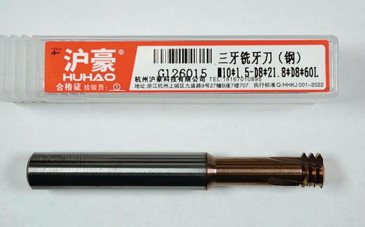
The cuttersavailable generally look somethinglikea tap with some threads removed, photo 11.However,this is misleadingsincethese tools have no helical element to the threadform. In addition thereare some variants depending on their abilitytoproducea full-form thread i.e.rounded crests and roots .The oneshown has three threads and will producea full form thread but only forone particular thread; in this case M10 X1.5.
To be continued
RichardLofing makes asteady to support long workpiecesonanML10lathe.
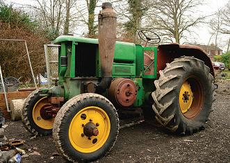
The SFV 302 tractor,5.3 litresingle cylinder semidiesel.
Myson has aMyfordML10 lathe, his granddad gave it to him on his twenty-frst birthday, It is used regularly making or repairing parts forour vintage tractors. We have amongst others, aFrench made single cylinder hotbulb tractor, an SFV 302, photo 1, We have hadit running but the fuel pumpleaks, as a previous owner had ftted the wrong fuel injector,and the excess pressure required to operateithas put acrack in the bronzecastingdue to hydraulicing action. Parts forthese tractorsare thin on the ground to saythe least,as
therewereonlya fewthousand built during the late 1950s, so it is acaseof making your own. Imade apattern to cast anew pump and being newto casting Istarted of casting the pump in aluminium alloy, forseveral reasons
1, Aluminium melts at alower temperaturethan Bronze, so slightly safer, and Ican getmyhands on loads of alloycastings such as water pumps etc, as my sonisamechanic forstock.
2, Icould test and evaluate my casting technique andthe pattern quickly
3, Icould check all the machining
operations needed on the aluminium before committing to bronzeonour limited equipment. Idiscovered thatthe pattern wasok, but it needs twoingates ratherthan one, so it feeds quicker,and Ineed to makemoreventilation holes in the sand as therewerea fewblowholes, especially on the underside. The pump is asimpleafair with one 2mm diameter piston with a18mm x1.5 thread at 90 degrees to the piston strokefor the one wayvalvesand a 14mm x1.5 thread at oneend fora bleed plug, using the cracked pump with a
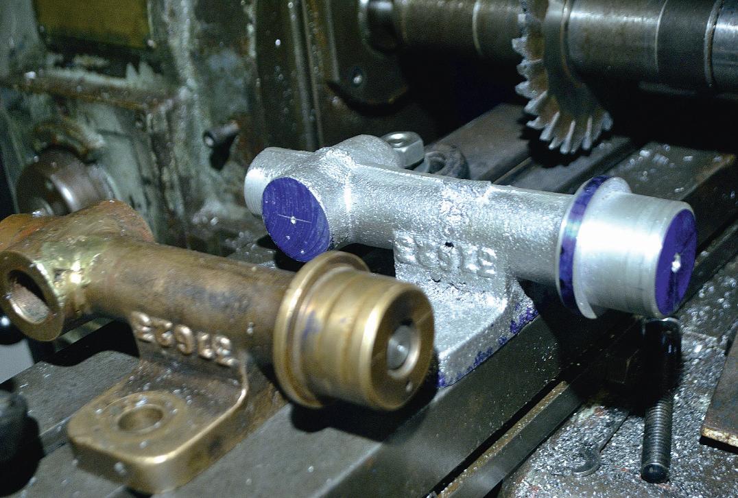

centred 12mmrod, photo 2,fttedin placeofthe piston Icould transfer the centres to the casting afer levelling the mounting foot in my shaper on the newcasting. Ihad thought Icould bore and ream the bodyfor the piston on my horizontal mill, the only operation Icould notdowas hold the pump and
machine agroove forthe ‘o’ring seal.IfI had afxedsteady Icould use the ML
Afew weeks previously the fanbelt had snapped on my car and it destroyed the bond on the rubber in the front pulley damper,the old one satonthe scrap pile;
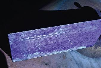
while drinking acup of tea it came to me thatthe centrepart of the old pulleywas about the right diameter and had alarge central hole andthree bolt holes, photo 3,ideal forthe fngersofa steady.All it needed wasthe outer rim removing, this washeld in placewitharubber strip which Ipushed of with our old Churchill screw press. Afer facingofinthe lathe I could nowsee the steady taking shape.
Obviously,a fxed steadyneeds abase to ‘fx’ it to the bed of the lathe, this Imade from apieceoftwo inch squaresteel thatcame from the base leg of adisused car lif, photo 4. Afer cleaning the
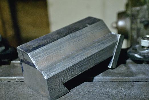
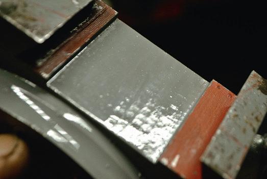
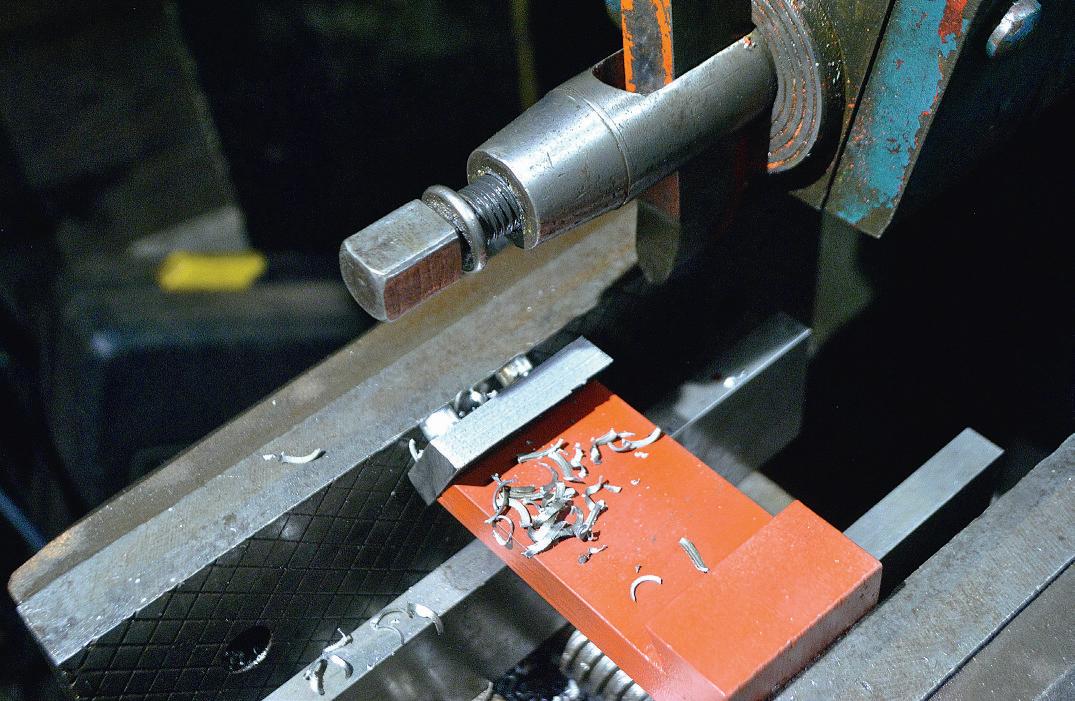
facesinthe shaperI marked out forthe dovetail and thencut this on the shaper afer grinding atool to about 55 with the dovetail angle being , photo 5, this wasanother frst forme. Icopied the base of the Rodneymiller attachment thatwehavefor the lathe, in thatthe centreofthe base thatcontacts the lathe bed is relieved, photo 6. Theretaining plate wasmade from an of cut of the gauge plate used to make the fngers. Although it didn’t afect its use Ileveled the bottom of the plateinthe shaper,
photo 7,soitwould sitstraight when notattached to the lathe. The next task wastojoin the twopiecestogether.For apreviousjob wherethe lathe wastoo small, Ihad made aMorse taper adapter so thatI could ft the three-jaw chuck onto the millingmachine. Thisalso fts the lathe tailstock as theyare both MT 2. By grippingthe ring in the centrehole in the chuck with the base clamped to the lathe bed, Icould mark the position of the twocomponents knowing they were in the correct position. Precision
wasnot too important in this case as the adjustable fngerswould takecare of alignmentwhen using the steady.I can hear the question ‘whynot use the chuck on the headstock’? Ihad thought of this,but with thewidth of the base and the body of the chuck,therewas not enough room
As thereisnot much ‘meat’ at the outer edge of the ringI decidedtouse four M5 cap head screwsand as luck would have
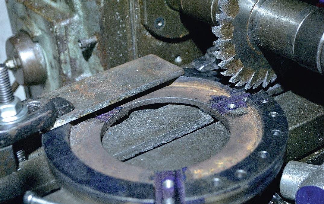
it, Ihad acounterborefor a5mm hole as the heads were right on the edge of aridge of the ring, photo 8. The other side thatfaced the base block was at Iwould have reallyliked to have set the ring in from the edge of the base, but until Ifnish arotary table build it will have to su cefor now, at least it is usable as is.
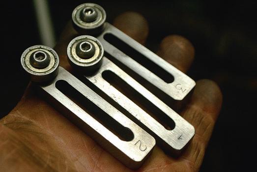
To makethe fngersI hadalength of 10mm thick gauge plate, photo 9, perhaps thinner wouldhavebeen better,
but Ihad it in stock. The three bearings were also in stock as Ihad bought a pack of ten when rebuildingthe guides on my bandsaw.The holes forthe bearings were drilled and tapped M6 at one end, this just lefthe adjustment slots. As Ihavenot gota vertical head formyCentec mill Iset up the Rodney mini miller attachmentthatcame with the Myford.Ipurchased anew 6mm slotdrill for£4froma well-known internetauction site and settoona wetafernoon. With the plate being so thick and the slotbeingrelatively
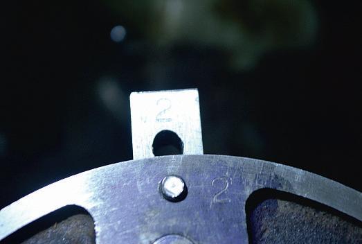
small it tookwhatseemed an age as I had to stoponeach passand clear the swarf from the emergingslot. So as to alleviate anyfuturefnger alignment issues, Inumbered each fnger and its matching slot, photo 10,atthe business end, wherethe bearings aremounted. Although it didn’t interferewith the operation, the squareends of the fngers overhung the bearing at the sides. So as to getthem all the same Iput aspotof superglue on each one and stuckthem together so when taking of the mill they stayedtogether.Imilled of the corners
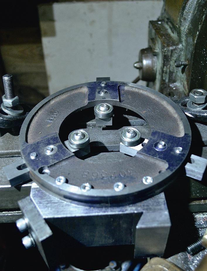
and then rounded them on the grinder before separating them.
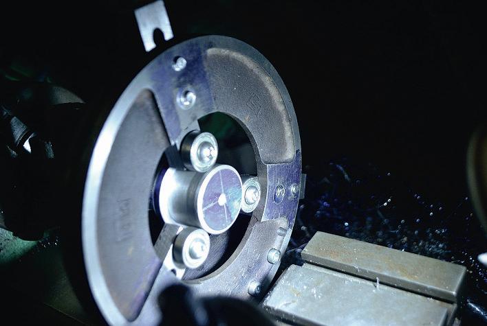
All thatwas lef to do construction wise wastomill groovesinthe ring for the fngerstolocate, plug the three existing holes in the ring,and drill and tap forthe fnger attachmentscrews. Ivaguelyremember when ftting the newpulleyonmycar on one of the forums therewas mention of there being an ofsethole. Drawing out the ring to sizewith paper and compass as my computer printer wasout of ink and drawing three lines to represent the fnger centres laying the ring on the drawing Idiscovered thatyes indeed thereisone ofsethole. As the holes are a‘tad’ over 11mm diameterI have turned three plugs from barstocktofll these by interferenceft. Icould then drill and tap these, M , once ftted to getthem oncentreline foreach fnger, photo 11.Again Iwished Ihad fnished that rotary tableproject thatI had started as it would have been somewhateasier to align the ring on the horizontal mill to cutthe three slots at 2 . As it was Imarked the centrelinefor each fnger on either side of theringand then used the scribed lines to align the cutter before clamping down. With one face of the cutter on the centreline Ithen wound the yaxis over half the width of the fnger and cuttodepth before settingthe depth stop.Soasnot to getconfused, Ithen wound the yaxis out the width of the fnger minus the width of the cutter and cut this side full depth, this just lefthe material in the middle which tookseveral passes to remove,perhaps Ishouldhaveused a wider cutter,but this wasthe only sharp onethatI had at the time. Atrial ft of the fnger in the slotbeforemoving confrmed thatmymath’swas correct! Thatlef twomoreslots to align and cut. Iused each fnger to mark fordrilling and tapping as the frst cut fnger slot wasslightly of centre, thereforeIused anumber punch to number the fngers and their respectiveslots.
With the fxed steady fnished it was time to giveita try, photo 12. As Isaid earlier the idea of the fxed steady wasto be able to cut agrooveinthe boreofthe pump to ft an o-ringseal, but onceon the lathe IdiscoveredthatI had enough
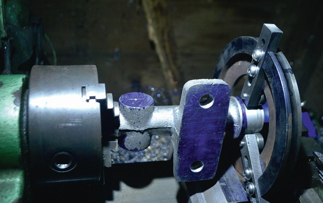
room to drill and ream the boreaswell. Ofennovices fnd it hardtosetup work in afxedsteady. The usual waywith something like abar of material is to grip the bar in the lathe chuck and then setthe fngersofthe steady with the baseclose to the chuck and then move the steady to where it is needed forthe machining operation, i.e. at the other end
of the work. In this casewithalumpy casting this wasnot going to be possible, photo 13.AsIhad centered each end of the pump body,Iset the castingup using the tailstock centreand machined the pump spring base at the end of the casting, this gave me agood area to set the fxed steady fngersintoposition before removing thetailstock.
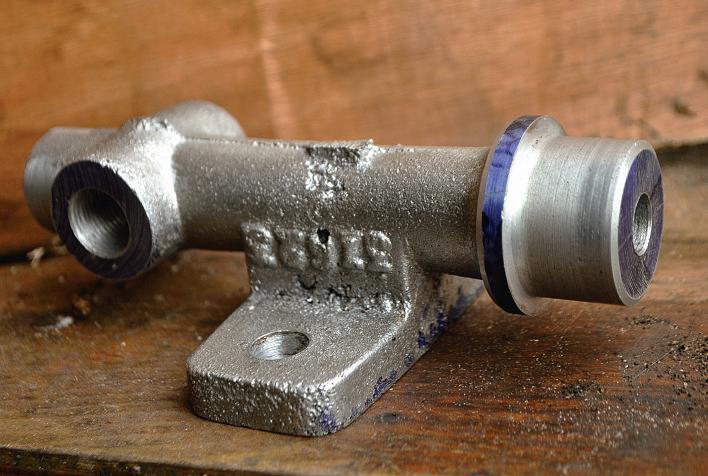
Icarried out all the operations on the alloycasting, except cutting the groove forthe o-ring, photo 14 ,so Iknewthe fixed steady wasusable. Idecided to finish it offwith acoat of machinery enamel, photo 15 ,all that’slefttodoiscast the pump in bronze.
