


EDITORIAL
Editor: Neil Wyatt
Designer: Druck Media Pvt. Ltd.
Publisher: Steve O’Hara
By post: Model Engineers’ Workshop, MortonsMedia Group,Media Centre, Morton Way, Horncastle,LincsLN9 6JR
Tel: 01507529589 Fax: 01507371006
Email: meweditor@mortons.co.uk
©2024Mortons Media ISSN0033-8923
CUSTOMER SERVICES
General Queries &BackIssues
01507529529
Monday-Friday: 8.30-5pm Answerphone24hr
ADVERTISING
Group Head of Investment
Model &Tractor Publications
Mason Ponti
Email: mason@talk-media.uk
Tel: 01732920499
Investment Manager
KarenDavies
Email: karen@talk-media.uk Tel: 01732448144
Talk Media,The Granary, DownsCourt, Yalding Hill, Yalding, Kent ME186AL
PUBLISHING
Salesand Distribution Manager: Carl Smith
Marketing Manager: CharlottePark
Commercial Director: Nigel Hole
Publishing Director: DanSavage
Published by: MortonsMedia Group, Media Centre, Morton Way, Horncastle,LincsLN9 6JR
SUBSCRIPTION
Full subscriptionrates (but see page 54 foroffer): (12months12issues, inc post andpacking) –UK £70.20.Exportrates arealsoavailable –see page 46 formoredetails.UKsubscriptionsare zeroratedfor thepurpose of Value Added Tax. Enquiries: subscriptions@mortons.co.uk
PRINT ANDDISTRIBUTIONS
Printed by:Acorn WebOffsetLtd., W. Yorkshire Distribution by:Seymour DistributionLimited, 2EastPoultry Avenue, London, EC1A 9PT TelNo: 02074294000
EDITORIALCONTRIBUTIONS
Accepted photographsand articles will be paid foruponpublication.Items we cannot usewillbereturned if accompanied by astamped addressed envelope, andrecorded deliverymustclearly statesoand enclosesuffcient postage. In commonwithpractice on other periodicals,all materialissent or returned at thecontributors ownrisk and neither ModelEngineers’WorkshopMagazine theeditor,the staffnor MortonsMedia Ltdcan be heldresponsible forlossordamage, howsoevercaused. Theopinions expressed in MEWare notnecessarilythose of theeditor or staff. This periodicalmust not,without thewritten consent of thepublishersfrstbeing given, be lent,sold, hired outorotherwise disposed of in amutilated conditionor, in anyunauthorised coverby wayoftrade or annexedtooraspartofany publication or advertising, literary or pictorialmatterwhatsoever.
This issuewas published on 18 September2024
Thenextissuewillbeonsale18October 2024


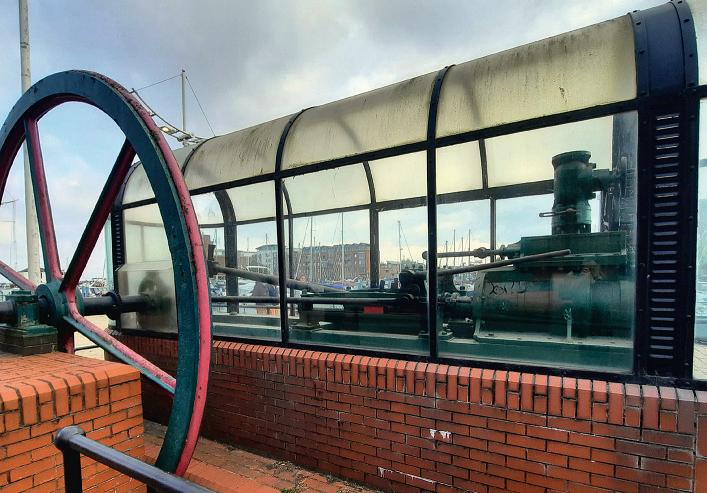
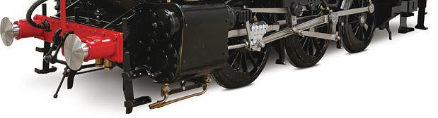
Last weekend Iwent fora short break which tookina visittoa friendliving near Hull Marina. Ifound an interesting example of engineering history.Itisa steam engine builtbyS&H Morton& Co.Interestingly,thiscompanywere primarily shipbuilders, buttheyalso produced slipwaywinch systems.
Thomas Morton invented the Patent Slip or ‘marine railway’, athree-railsystem thatalloweda wheeled cradle to be used to move ships in and out of the water. The engine wasused topower such a system. The engine, poweredbya coal fred boiler)was originally housed in the former WindingHouse at Plimsoll way. The Winding House is nowluxury fats and wasthe only docksidebuilding retained when the area around Victoria Dock wasredeveloped.
It appearstobea fairly conventional single-cylinderhorizontal mill engine, at frst glance, but acloser look suggests morecomplexity,presumably to allowfor reversing and ‘inching’ the load. The valve gear appeared to be operated manually by large,heavy lever– althoughImay be completelywrong aboutthat.
Unfortunately Ididn’t have time to work out exactly howitmay have operated, and the enginesits inside asort of Perspex‘bus shelter’.This is notgood forphotographs,thanks to refections and the accumulation of scratches and grafti (ithas been there over 30 years).It’sashame this rather special engine couldn’tbedisplayedina more attractiveand accessible way. It would makea fascinating subject to model, I’dbeinterested if anyreaders have more information, access to decent drawings or knowwherethereisamore accessible engine of similar design.


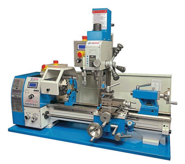


9 Machining Large Diameters
Adrian Garner compares and explains two contrasting approaches to generating large circular cuts on the lathe and milling machine.
16 Poly Vbelts fora Myford ML7
John Olsen upgraded thebelt driveon his Myford ML7using Poly-V belts. e e lains howtomakeand ft the specialpulleys required.
22 From the Archives
In this issue we revisit someideas for repairing worn out G-clamps.
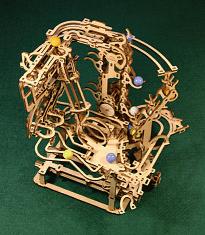
26 Building aMarble Run Chain Hoist
Embarked on while waitingfor his newworkshop to be ready,Mark Noel completes this complexUkrainian wooden construction kit.
30 Struck Ball Hardness Testing
Jaques Maurel follows on from last month’s VickersHardness Tester by looking at asimpler comparative approach.
34 Pull-Out Print
Our centrepagesthis month feature‘The Lathe’byJeanette Chadwick
38 Beginner’sWorkshop
Geometer shares some approachesto making artstoftcom le contours
40 Using aBall Turning Tool
From time to time, it’suseful to be able to turnaccuratespheres on the lathe. Here’s howtoset up and useaball or spherical turning tool.
45 Getting To Love My DenfordNovaturn
Mick Knights movesontorunning the VRTurn softwareonhis CNC lathe.
50 Tool tip zero setting for DRO lathes
Simon Davies’ found repeatability problems when changing tools on his
DRO equipped lathe, he details his solution.
58 Stevenson’s Trophy Update
Here’s an update on howtovoteinthe 2024competition –you have until the end of the month.
59 Headstock Indexing on the Minilathe
MikeCox’s simple changewheel indexer o ersa waytoachieve accurate indexing of awkwardnumbersof divisions.


In our ne t issue eo ndrewsmakes an oversi e face late fora small rotary table anddescribes how to use it.
3 On theEditor ’s Bench
The Editor discoveredanunusual steam engine in Hull
14 Scribe ALine
Another fascinating month’s postbag with some interesting news from our readers. We arealwayskeen tohear from you–send the editor your thoughtsatmeweditor@mortons.co.uk.
16 Readers’ Tips
This month our winner is asimplebut clever tipfor mixingsmall tinletsofpaint. Send your tips to meweditor@mortons.co.uk,you could win a ri e.
36 On theWire
This month vacuuming the railways (noitisn’t thewrong type of leaves!) and listening to marine engines
64 Readers’Classifieds
This month’s collection of readers’for sale andwantedadverts.
Ourcover featuresMikeCox’s
flexibleheadstock indexingdevice inplaceonthe headstock of his mini lathe. Formoredetails and construction drawings see page 59


Visit the Model Engineer Forum to see and vote forthe entriesinthe 2024Stevenson Trophy Competition. Or search the forum for‘Stevenson Trophy’ www.model-engineer.co.uk/750953/cast-your-vote-in-the-2024stevenson-trophy-competition/
Hottopics on the foruminclude:
Whatshape is aspirit levelbubble? Started by DC31k
Perhaps more of aphilosophical question than apractical one, this has certainly gotpeople talking..
Setting up and mounting machine tools in amobile workshop
Started by Mark Brockley


Howwould yougoabout mounting machines in atrailer or caravan?
Stuart Twin Victoria (Princess Royal) Mill Engine
Started by Dr_GMJN
Along thread on an fascinating engine build, with interesting discussion of di erentmachining challenges.
Come and have aChat!

As well as plenty of engineering and hobbyrelated discussion, we arehappyfor forum memberstouse it to share advice and support. Come and join us –it’sfreetoall readers!


Adrian Garner explains twoapproaches to generatinglarge circular cuts on the latheand millingmachine.
The 10” swing on my Myford lathe is usually morethan sufcient for model and clock making needs but occasionally something bigger needs to be turned. In this event thereare twoo tions, takethe art to the club worksho and use one of their large lathes or fnd away to machine at home.
y local club is the ociety of odel and erimental ngineerswhich has very fully e ui ed worksho s able to machine arts IdoubtI could li or large heavy castings this is defnitely the best solution. Parts only moderately bigger than the swing on the Myford, however, can be machined at home with alittle ingenuity.
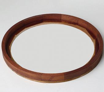
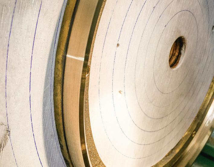
s illustration Irecentlyhad the need to machine aclock be el (the brass ring around the clock face)for aregulator clock Ihavemade which is ustover diameter. e elscan be made by bending and bra ing brasssection but in this case, it wastobemachined from abrass casting made from a attern by afriend and e cellent clock maker, ake utton, photo1. oth ake and Io ted fordi erent solutions to machining these castings bothsuccessful and each with its ownadvantages and disadvantages.
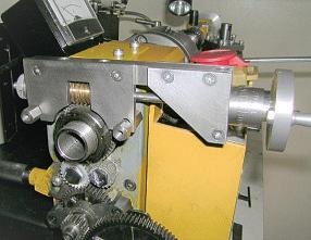
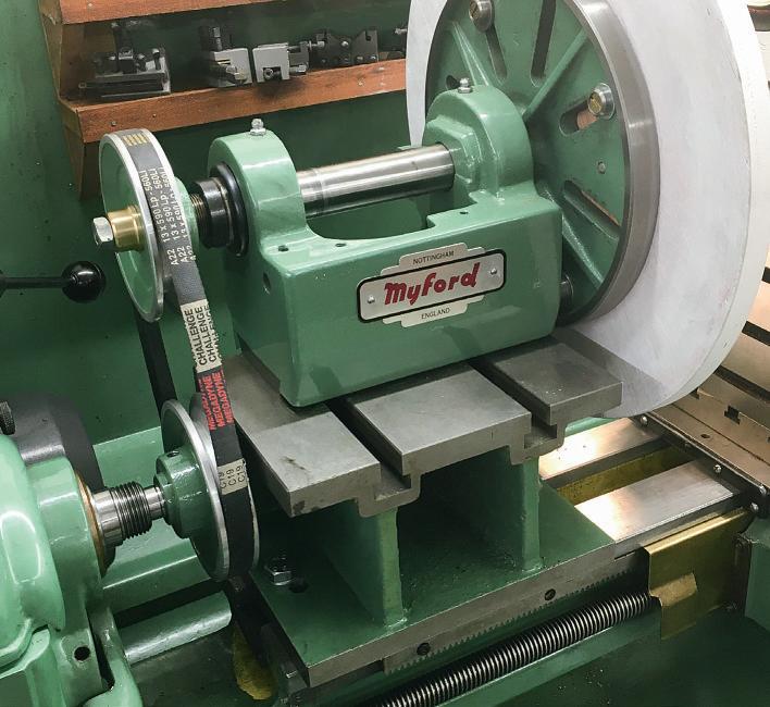
ake turned his be el by increasing the swingofhis Myford lathe. Anumber of ways to do this have been published inthe Model Engineer overthe years which re uireasignifcant amount of construction. ake’ssolution wasto ac uireadisused yford 0head stock o the internet. hen mounted on ablock the raised mandrel was driven via pulleys from the mainlathe mandrel. his solution had the distinct advantage of providing astandard
yford nose towhich a yford face late could be attached. he machined base of the raised yford head tock and the facesofthe block led to the mandrel beinglevel withthe lathe bed (withinthe tolerance needed)but the raisedheadstock had to be aligned with the bed easily checked using adial gaugeacross the face late. As no drilling wastobeinvolvedthe raised mandrel did notneed to be accurately aligned with the tailstock, photo 2. o match theincreased height of the mandrel overthe lathe bedit wasnecessary,ofcourse, to raise the
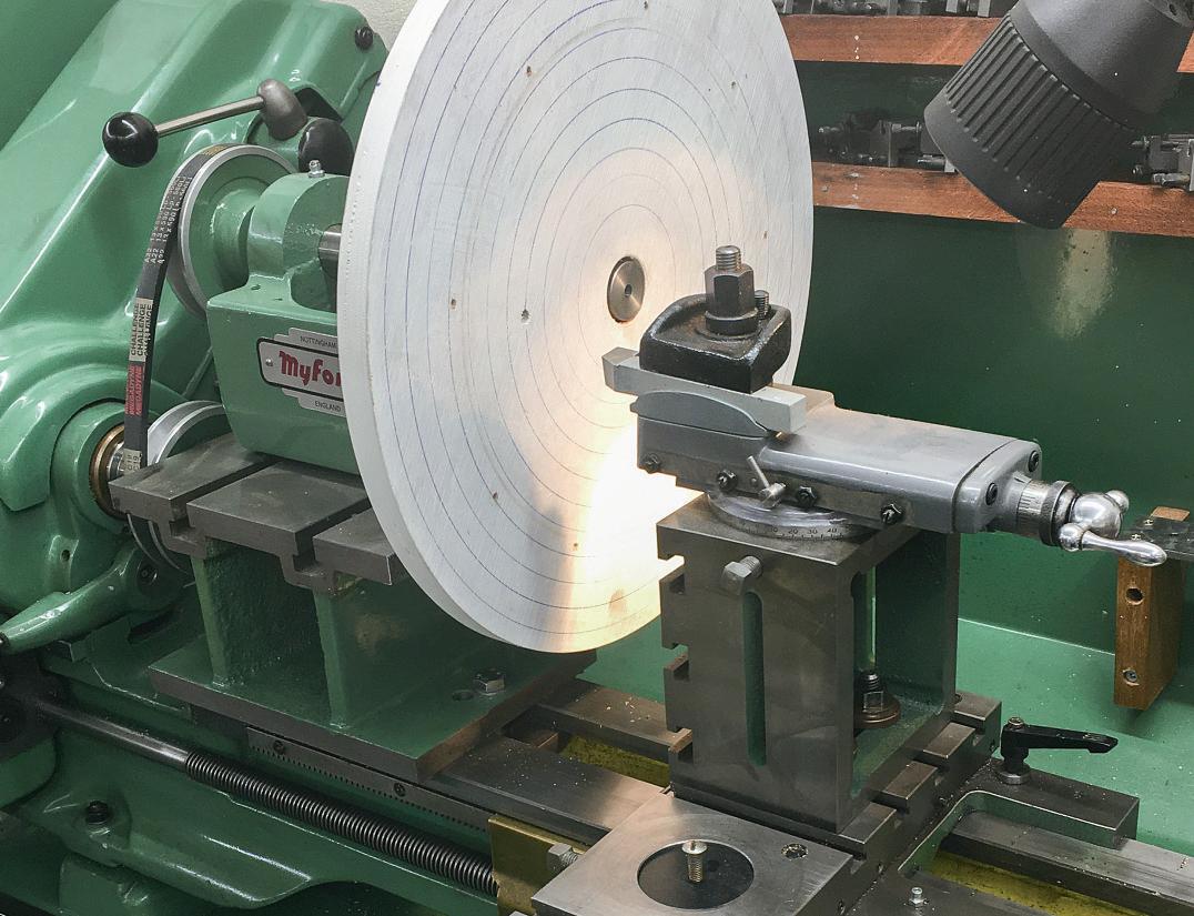
cutting tool to the newcentre line. his wasagain done with acast iron block, photo 3
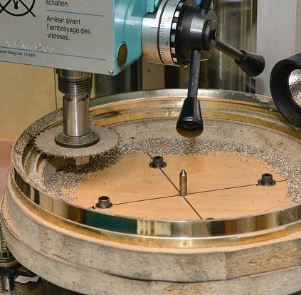
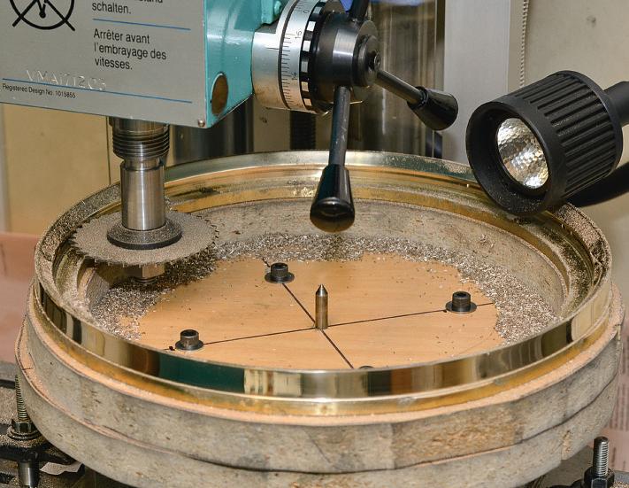
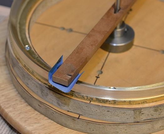
o securethe be el casting anumber of smallholesweredrilled in the waste art of the casting to allowittobe screwed to adisc of wood thathad been mounted on the face late. entring was made easybydrawing concentric circles on the wood surfacewith a en whilst rotating the face late, photo 4 hen turning suchlarge diametersit is essential thatthe rotation rate is low, even with brass. The “ruleofthumb” that300rpm is optimal for1”diameter mildsteel (e uivalent to acutting s eed of around eighty feet er minute)leads to arotation rate fora diameter of 11” of 300 ,say r m forsteel. his can usually be doubled forbrass but halved forcast iron but these fgures assume arigid setu . he e ualsi ed ulleys in ake’s setu workedfne forbrass usingthe lowerspeedsofthe Myford,
Afer mounting on the rotary table an initial cut wasmade across thetop ofthecasting.
photo 5. further reduction could be made if needed by changing the ulleysi es. mall cuts at lows eed will minimise chatter
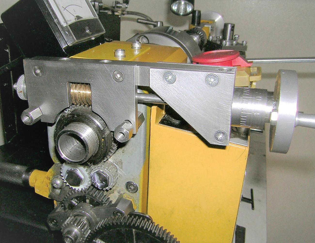
Io ted to mill the casting. y vertical mill has a24” by 6” table andreadily
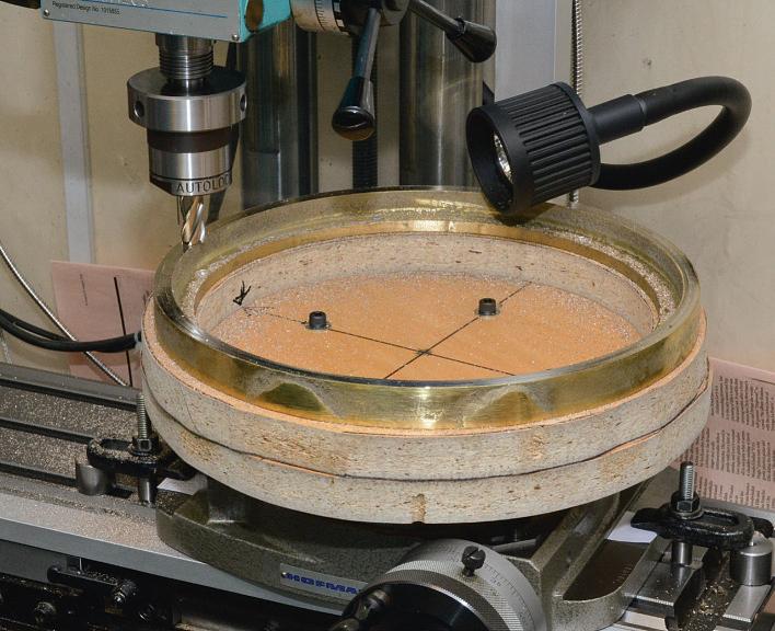
takes an diameter rotarytable. o securethe casting an a ro imately diameter disc of mm thick melamine coated chi board(e chea furniture) wascut out with the igsaw together with adonutshaped ring from the same material which had a diameter central hole. i symmetrically ositioned
wood screwsheld these together. i 3 clearing holesfor screwswere then drilled in the brass casting’sinner (waste)li to allowittobescrewed to the wooden support.
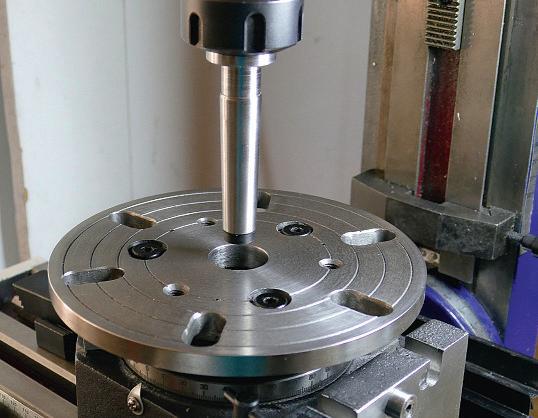
ith the re aration com lete, the rotary tablewas mounted onthe mill and the centreofthe uill aligned with the central hole in the rotary table. he igital ead uts were setto ero. It should be noted thatitwas necessary to mount the rotary tableatthe far right handend of the table so thatwhen the milling head wasswung to mill the curved chamfer on the be el (see later) contact between cutter and metal could be made.
he wooden mountand casting were then bolted to the rotary table. The clearanceholes forthe four bolts on the wooden mount had been made oversi e so thatitcould be manoeuvred to bring the casting to as near as ossible acentral osition on the rotary table. Iused adialgauge on the outside of the castingwhilst rotating the rotary tabletohel udge the osition. he readings on the dial gauge varied alot due to the rough e ternal surfacebut it waspossible to getitpretty near to the optimum position before drawing the bolts up tight.
er doublechecking allscrewswere tight, Ilockedthe slides and took acut across the to surface of the be el by rotating the rotarytable. he cut was ust sufciently dee to clean u the surface. Iused a diameter end mill, photo 6. he inner surfacewas tackledne t using the same end mill. hecut was again setto rovide aclean surfaceon onerotationofthe rotarytable but the de th ( a is ) of cut wasmodest at about 0.0 0 in order to minimise cutter marks. his meanta large number of rotations were necessary h fora powerfeed on the rotarytable –but the resulting surfacefnish waseasyto olish. he e ercise wasre eated on the outer surface.
Iwanted my be el to have aconcave chamfer on the inside edge, he vertical mill is erfect forthis without anys ecial cutters. o generatethe concave chamfer the milling head was swung forty fve degrees. Ienlisted my wifetohelp with thisoperationinorder to ensure the head didnot accidentally
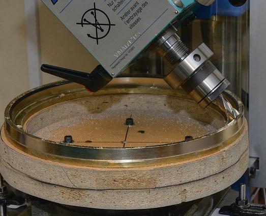
swing right overbeforethe bolts were fully secured. ouhavebeen warned
The rotary table wasalso moved inwards on the “y axis” so that the end mill wascutting on the leading edge of its motion with the trailing
edge in the wind. The resulting shape is nota fatchamfer as thegeometry of the motion of the cutter will be to generatethe desired shallowconcave cut, photo 7. he amount of curvature is small, but it is attractive and is easier to olish using one’s fnger as the abrasive su ort
Before polishing and parting the be el from the casting Idrilled a hole centrally on the wooden su ort. ( his wasthe reasonI had centralised the
rotary table under the uill). he hole served twopurposes.
1The next operation wastopolish the machined surfaces of the be el. er removingthe casting with the wooden support still attached to it from the rotary table, the holealloweda length of diametersilver steel to be inserted to actasthe ivot forrotation of appropriately sha ed wood around which the polishing abrasives were wra ed. I ur osely carried out
this polishing away from the mill –machine tools and abrasivegrit do notgowelltogether, photo 8 nce olished the hole lus eg made it easytoremount the whole sufcientlycentrallyonthe rotary table forsubsequent parting of thebe el.
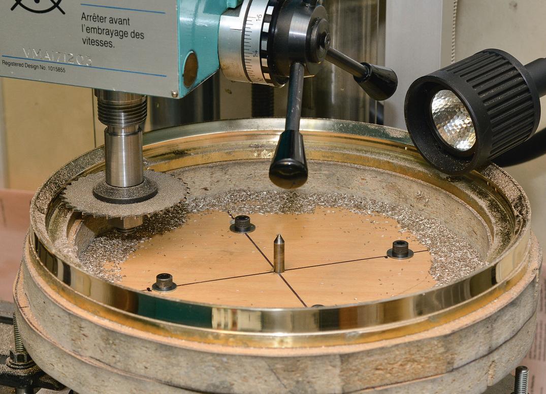
The parting wasdone with a1/16” x 3” slitting saw rotatingat130rpm. The initial successivecuts were made from inside the be el ring. hese cuts formed the inner ste at the rear of the be el for the face to rest in, photo 9.
It should be noted thatinorder for these cuts to be ossible therehad to be room forthe cutter lus holder within the casting this wasthe reason forthe otherwise unnecessary donut layerof the wooden support.
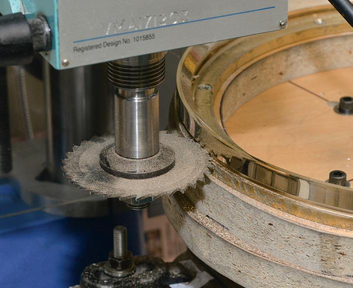
The same slitting saw wasthen used from the outside of the casting but with the saw loweredtogeneratetothe needed step, photo 10
If the face is made from or . mm brass, then the cutter will need to be loweredbyabout 0.060” to leave the face slightly ro ecting at the rear so thatitcan be gri ed by the screws in the be el. (Inmycase, unusually,the face is thicker so Itook additional cuts on the inside ste ,but the rinci le is the same).
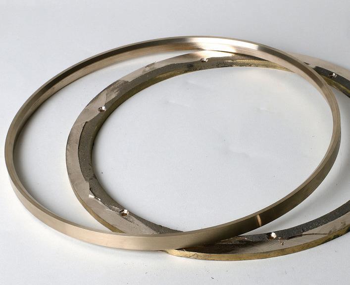
The results areshown in the photos 10 and 11. easurements taken during machining the be el indicated thatI could comfortably machine a diameter withouta problem on my mill. Thediameter is essentially limited by the throatdepth of the mill.
hich method is better oth work. ormoredelicate work,such as this be el, milling avoids roblemswith chatter marks thatcan be formed in the lathe if the tool is notsharp or the rotation speed too high. These can be difcult to olishout. gainst this, thereisnodoubtthatmilling is signifcantly slowerthan turning in the lathe and requires manyturns of the rotary table handle. mill would no doubtautomate much of the operation.

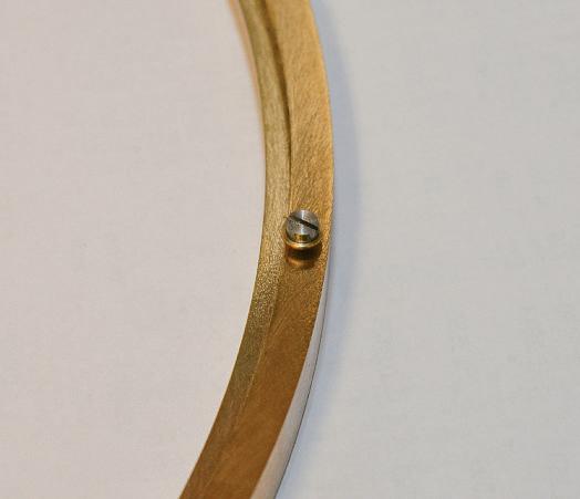
The rear face ofthe bezel has astep into which the face is mounted.This is securedby 8BAscrews(still to bepolished andblued in thephotograph).Take carewhendrilling forthese screws- do nottogotodeep and ruinyour bezel!
Readers! We want to hear from you! Drop us aline sharing your advice, questions or opinions. Whynot send us apicture of your latest workshop creation, or that strange tool youfoundina boot sale?Email your contributionsto meweditor@mortons.co.uk.
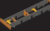
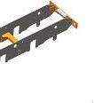
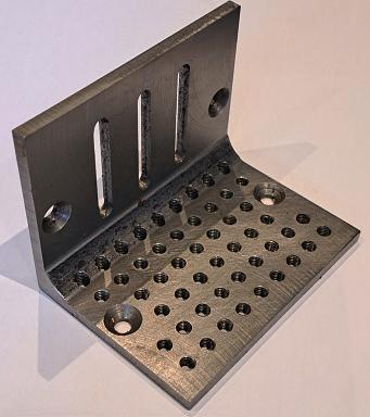
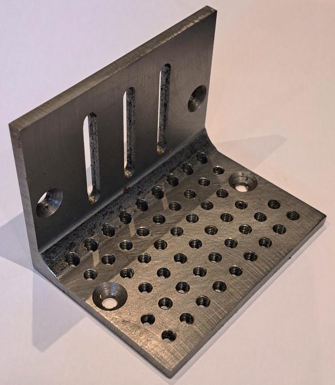
Dear Neil, it wasinteresting seeing the use of angle iron in “A Workshop Diary”,Sept24issue of MEW.The attached photo is of asimple angle plate thatsimilarly started life as apieceofangle iron and wasbrought to shape by milling and fy cutting. It canbe bolted to afaceplate, themill bed or heldinthe vicefor mounting awkwardparts andhas proved its worth anumber of times now. The countersunk holes allowedit to be bolted to themillbed whilst fy cutting the inside surfaces. The other thing worth notingis thatwhilst angle ironistypically around 6mmthick,8mm isalso obtainable and givesincreased rigidity.
ere’s areminder that avid rith’s latestInde for odel ngineers’ orksho can be downloaded on from the orum at www.model engineer.co.uk ustsect orumsand then the odel ngineers’ orksho to ic. lternativelyscan the ad acent code. If you referthe a er inde es, don’t worry, avid willbe roducing these in thefuture, carrying on Barry Chamberlain’ssterlingwork.

Dear Neil, with winter nowfast a roaching Iwonder if thereare any books (engineering)thatyour readers could recommend my reading through the coming dark evenings?To“return the favour Ican recommend ives of the Engineers” by Samuel Smiles. ong out of rint but suretobein ibraries or on sale on the web, Ifound this biographyofBoulton and Watt a fascinating read.
All the best, “WingNut”, by email
Hi Neil, the recent article onthread millingbyBob Reeve, reminded me of atask setbymy“inventive”boss back in 1978. The requirement wastoproducealong lead (about 1.5inch lead and about0.5inch diameter)s uaremulti start thread to be art of a rototy e rotary actuator. he setu tomachinethis, em loyeda yford ftted with atoolpost millingattachment, with asmall throw away cutter. Due to the arrangement of changewheelstogeneratethe long lead, the headstock wasactually driven by handusing atailstock handwheel.Iguess oldage is also kicking in as Ican vividly remember making the male thread buthavenorecollection of howthe matching nuts were produced
Dave Fenner,byemail
DearNeil, Smarting alittle still, Icongratulated myself on the preservation of my composure. The only outwardsign of any distress or annoyancemay have been the palm of my handpassing overmybalding pate to smooth down the fewremaining hackles.
“Oh it’salright foryou playing aboutinyourshed, you’vegot all the time in the world nowthatyou areretired.”
The word “playing”,used to describe activities in my shed, having caused the gravest o ence Idecided thatattack froma di erent uarterwould form the strongest line of defence. To the delightofthe othersstood at the barI addressed my interlocutor “Better to staysilent and be thought afool than to speak out and confrm it. uttered a roval from the morematureclientele confrmed Ihad the su ort of back up forces. My opponent returned apathetic parry to my
hammer blow with asolitary “How so?”
t length Ie lained thatwith timepassing as it does,and that oncepassed it irrevocably was nevertoreturn, the very fact that he had acknowledge thatI had retired and thatthereforealarge portion of my time had passed ow the devil could Ihaveall the time in the world?” Applause and “Collapse of stout party” to quote the doctorswaiting room magazine Punch.
Ona slightly moreserious note, with time nowata remium, I have found thatthereisacertain pleasure to be had in the careful lanning out of a ob before sallying out to the bench and tools to carry it through. We all remember the chant from management that“Timer is money” Well nowitisevenmore precious, and abit of planning can paydividends.Well,not actual dividends but time fora second
biscuit with your morning cuppa. y lanning Isim lymean your approach and methodology forcom leting the ob in hand Forinstancesupposeyou are required to maketwo identical components in the lathe, the direct straight forwardway would be to makeone and then repeat the process to makethe second. But whatifyou could machine both items at oncewithout removalfromthe chuck and then sim ly art them o oun chucking and re chucking, and no setting and re setting of tools. ust asilly e am leI grant you, and the time savedminimal but if and when youdopuzzle out some cleverwheezefor working, the muttered “You cleverold sausage” is areal bonus.
To followers of PatienceStrong who note elf raiseisno raise at all ,tothem Isay i e .
Paul Tiney, by email.
h s o th s s o th s p pto o st p t
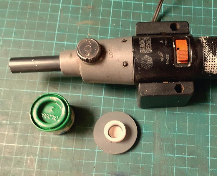
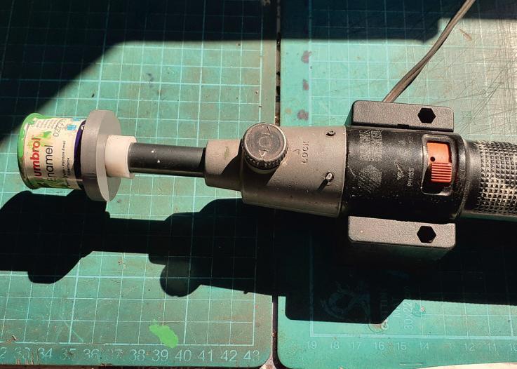
Iwanted aquick waytostir some Humbrol paint so riggedupwhat yousee in the pics thereisabutton magnetinthe centre of the nylon paint tin holder
o
h 30 o h s
o t s o s pp s h st h oo s o h o th s op p Email your workshop tips to to o to s o marking them 'Readers Tips',and youcould be a winner.Try to keep your tip to no morethan 400 wordsand a pictureordrawing. Don’t forget to includeyour address! Every month we'll choosea winner for the TipoftheMonth will win 30 o h s o h st h oo s.Visit h st ho sto o to plan howtospend yours!
lease note thatthe frst prizeofChester Vouchersis only availabletoUKreaders. Youcan makemultiple entries, but we reservethe right not to awardrepeat prizes to the same person in order to encourage newentrants. All prizes areatthe discretion of the Editor


Some yearsback Iwas having trouble with thebelt driveon my Myford ML7. The Vbelts would heatupthe pulleyonthe main s indleand the ress ft between the pulley and the back gear would come loose. This happened enoughtimes thatI decided it wastime forsomething better.Poly-V belts were an obvious answer, photo 1,and in fact my late father,who ownedthe lathebeforeme, had thought about thisand gotasfar as buying some pieces of continuous cast iron bar to makethe pulleys from. There is akit from Hemingwaytoperform this modifcationona u er , but a arently thereissufcient di erence to makethis notapplicable to the ML7 o Iwas on my own.
Abit of research convinced methat Ishould be able to ft in four ste s instead of the original three, and that sincethe poly-V belt will happily wrap around asmaller diameterthan the original Vbelt, Ishould also be able to geta slightly wider s eed range. ince the ML7has plain bearings, higher speeds need to be considered with a bit of care, but an increase of maybe 10% is notgoing to cause too much of aproblem. The belt is tensioned in the same wayasthe Vbelts were,by the lever, and this also acts as before to disconnect the drivesothatwhen setting up the chuckcan be turned by hand without trying to turn the motor The advantage of the poly-V beltis thatitismorefe ible so transmits the powerwith less heating of the beltand pulley. It also needs less tension, so thereisless loading on all the bearings. The belt Ihaveused is aPJ660.The PJ refers to the belt’ssection, and the 660 is the length in millimeters. These belts aremade as alarge width and then the supplier cuts them to the width you need, which in ourcase is 6ribs. This
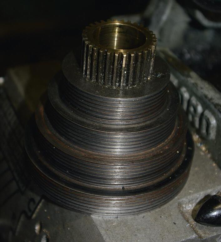
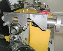
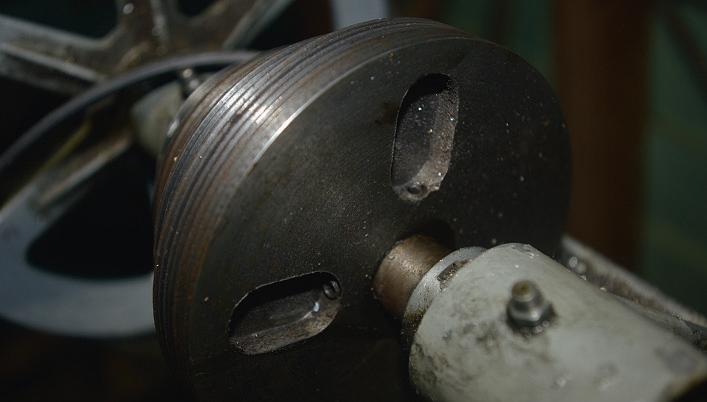
Themainspindlepulleywith the bronzebackgear slee eftted.
seems tobeplenty,atleast in over ten yearsI haven’thad to replaceone yet. he waythatthe e traste is ftted in is by counter boring the largest step on the s indle ulleytoallowittoftover the s indle bearingatthe le handside. This allows it to line up with the small ulleyonthe countersha , which is also counter bored over the plain bearingat thatend. This leavesaboutthree eights of an inch at the right hand end of the countersha clear of the bearing, which is just enough to allowtwo grub screws which areangled in from recesses on the
end face of the pulley, avoiding the need to have holes in the belt running faces. Akey would be nicebut would be abit of awangletoft, since the countersha has to be fedthrough the bearing at one end, then through the pulley, and then through the other bearing. This means thattherewould only be about 3/8” available to ft the keyinto lace. he grub screwsturn out to be sufcient, rovided theyare each given asmall fat to bear on the countersha .
As mentioned above,Iused continuous castironbar to makethe
Ea sy ru nn in gf it on ma in sp in dl e
pulleys,although other materials likealuminium couldbe perfectly satisfactory.The Vgrooves arecut with asinglepoint tool ground by handto matchthe belt. ome care is needed in actuallycutting the grooves, since the spacing is an awkward number,and youdowant the groovesonall steps to line up with their opposite number accurately.The tool used is asingle point cuttergroundtocut a40-degree V. Theside of the tool needs to clear the ne t ste ofthe ulleywhen you aredoing the smaller steps, so the point of the Vshould only be about .0 0 from thatside. small fatisle on the pulleybetween eachV groove since the belts have aslightradius on the inside. Ifound0.030”about right forthis. Trytokeep thegrooves centred on each pulleyfaceand correctly spaced.
The ideal waytodoajob likethisisto takethe s indle and countersha out of your lathe, takeall the material around to another machine, and do the job there. Ididn’t have the lu uryofaccess to another machine at the time, so had to rely on takingaccuratemeasurements with themachine apart, then reassembling it to do the turning, then taking it apart againtoassemble the job.Ican giveyou the dimensionsthat work with my machine, but it might be worth your while to check these against your own, sinceitisnot uncommon for manufacturers to change thingsoverthe years. o frst letusdismantle things. he countersha should be no roblem, takethe collar o one end and the set screw out of the ulley and the sha should pull out through the bearings. Forthe spindle, the gear on the end is going to have to come o . hisisa
featurethatshows thatthe Myford was built down to aprice,since it is secured by meansofa grub screw tapped into the side of the gear so thathalf the hole is in the gear and half in the sha . his is acheap and nasty wayofdoing things, sinceonreassembly youhavetotweak thegear around untilthe screw will go in, which is noteasysince the gear is a ress ft. houldyou ever have to re lace the gear,you will have to drill and tap anew hole in adi erent lace, sinceit is impracticable to tap half ahole in the new gear. e ttothe gear is ascrewed collar which allows adjusting the end foat. his is locked by agrub screw which should be loosened, and then the collar can be unscrewed.Between it and the bearing housing is athrust collar, which is made to rotate with the sha by avery small pin. Trynot to lose the pin. On mine the grubscrew on the collar
Diametersapplyfor both pulleys Allsteps arethe same width0.617”
has atinybrass pad inside whereitbears on the spindlethread. This is to prevent damage to the spindlethread, which would makeithardtounscrew the collar
Nowyou can undo the capscrews thathold down the bearing ca s. i the ca s o and ut themaside,kee ing withthem anyshims theyhad under them. Make sureyou canput anyshims back in the same placetheycamefrom. Idon’t knowfor sure if such shims area standardfeature,but mine has some. The bearings themselves can be ad usted by eelinglayerso them, but Iamnoe ertindoing thatand willnot go into it here. Trynot to lose anyofthe small parts, especiallythe pin andthe grub screw.The grub screw is probably ,which might be abit hardtofnd these days
o by nowyou should be able to li thespindle out of the lowerbearings and
disentangleitfromthe belt. The Thrust bearing should be removedfromthe sha , and a er thatthe e isting belt pulleyand small back gear should come o the sha as aunit.
Nowyou need to remove the bronze back gear from the pulley. Mine was loose, so no problem, butifyoursis atight ft youmay need to heatthe whole assembly.The aluminium pulley will e andmorethan the bron e gear and sleeve,and youshould be able to persuade it out. At thispoint, youneed to measurethe outside of the sleeve, sincethis is one dimension Idonot have. My sleeve is nicely attached in the new ulleyand would be difcult to remove In anycase, since youwill want agood ft, it is better to check thisdimension against your ownone. Youwill need to borearecess in your newpulleytotake the sleeve,which wants to be either
areasonable ress ft, or failing thata good enough ft for octite to retain it. his ft takes all the drive from the ulley to the back gear,and from thereeither directly to the spindle or through the back gear sha ifthatisengaged. o you don’t want this to come loose as mine wasdoing.
Nowwecan start to turn the pulleys, or at least we can if we have access to aworking lathe! At thispointI had to reassemble mine enough to enable me to turn all the parts, and then disassemble and reassemble with the newparts. Thepulleyblanks arequite big lumps, but notbeyond the capacity of the Myford.Itisa while sinceIdid mine and Idon’t have photosofthe setups Iused, but thereare acouple of possible ways to proceed. Figure1 shows the details of the counter bores in the main spindle pulley. Thegrooves areonly shown on one step but will appear on all four Figure2 shows the diametersofthe steps forbothpulleys The width of each step is 0.617inches, and of course the total width is 4times that, or 2.468 inches. If your blanks are only about the length needed, youcan grip one end in the chuck,and turn the large end fatand make the recesses in it. Youcould the gripthe recess in the end with the internal jaws, and proceed to turnall the outside diametersand groovesand borethe main bore and the counterborefor the sleeve all at one setting. If thatseems tooprecarious youcould do the mainborewhile you aredoingthe recess, then makeup atemporary mandrel to holdthe job by whileyou turn the outside. uch a mandrel could be held between centres. Iwould suggest using the mandrel a roach forthe countersha ulley at least, sincethatonly needs apiece of bright mild steel bar.The important thing is thatthe internal bores and the outside pulleydiametersshould be concentric to each other.I’veo en had blank looksfromguyswhen Isuggest turning jobs between centres, but it is areally goodway to go when youwant things trulyconcentric. Photograph 1 (earlier)shows the mainspindle pulley with the bron e gear ftted to it. he rocess forthe countersha pulleyissimilar,but it is simpler sinceithas aplain bore with only a short counterboreatone end. This
counterboreisneeded to allowthe pulleytooverlap the end of the plain bearing. The counterbore is at the end with the smallpulleyand should be 1.125 inches diameter by 0.400 deep. The largeend needs the recessesmilled forthe twogrub screws. Figure3 shows this face of the pulley. The holes then need to be drilled and tapped at an anglethatclearsthe end of the recess. Iused M4 grub screwshere. Photograph 2 showsthe largeface of the countersha ulleywith the recesses forthe grub screwswhile fg. 3shows the dimensions forthe slots Iused. Figure4 showsthe details for cutting all the grooves.
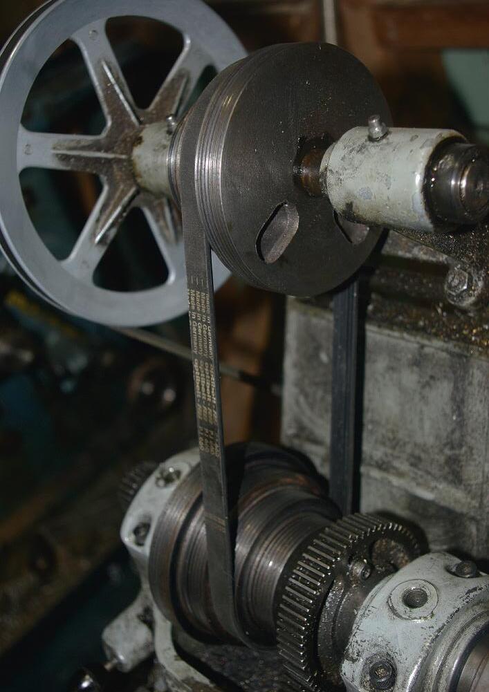
Oncethe parts aremade youshould be able to reassemble it all, remembering to put the belt in. Photograph 3 shows the assembled drive. Before anyone comments, yes, the guardisnot in place. It wouldfoulthe small end of the countersha ulley. It is also uicker to change stepswithout it. It could be modifed to allowreftting it if you wish. Also the oilershad notyet been reinstalled when the photo wastaken. Incidentally,aswell as the four-step pulleys,mymachine has avfd driveonit. Both these methods of speed changing have their place. The vfdisgood for changing speed quickly when doing things likescrew cutting.A slowcut towardsperhapsashoulder,then aquick reverseback to the start of the cut. It is also handy fortweakingthe speed by just asmall amount to see if chatter can be eliminated. The belt steps aregood forchanging the overall torque/power/ speed relationship,sothatthe lathe is runningslowfor large diameter jobs and fast fortiny obs. lowing down for large diameter jobs simply by reducing the vfdspeed also reduces the available power, so it is better to step down on the pulleys to allowheavier cuts on the larger jobs. This becomes important when youfnd youneed to takea fairly heavy cut on something likea cast iron fywheel to getunder ahardskin. hile we arediscussing changingspeeds, it is quite easytochangethe poly Vbelt from one step to another in much the same wayasthe old Vbelt.
It should be possible to align the groovesonthe twopulleys by adjusting the countersha ulleya little le or right. Give all the running parts agood