Talk Media, TheGranary,Downs Court, Yalding Hill, Yalding,Kent ME18 6AL
PUBLISHING
Sales &Distribution Manager: Carl Smith
Head of Marketing: Charlote Park
Commercial Director: Nigel Hole
Publishing Director: Dan Savage
Published by: Mortons Media Group,Media Centre, MortonWay,Horncastle, LincsLN9 6JR
SUBSCRIPTIONS
Full subscription rates(see inside forofers): 12 months, 12 issues, inc. post &packing- UK £71.40. Export ratesare also available, see www.classicmagazines.co.ukfor moredetails. UK subscriptions arezero-rated forthe purpose of Value Added Tax.
Enquiries: subscriptions@mortons.co.uk
PRINT ANDDISTRIBUTION
Printedby: Acorn WebOfsetLtd, WYorkshire.
Distribution by: Seymour Distribution Limited, 2East Poultry Avenue, London, EC1A 9PT Telephone: 020 7429 4000
EDITORIAL CONTRIBUTIONS
Acceptedphotographs and articles will be paid forupon publication. Items we cannot use will be returned if accompanied by astamped addressed envelope, and recordeddelivery must clearlystatesoand enclose suficient postage In common withpractice in other periodicals, allmaterialissent or returned at the contributor’sown risk, and neither Model Engineer &Workshop Magazine, the editor, the staf,nor Mortons Media Group Ltd can be held responsible forloss or damage, howsoevercaused.
Theopinions expressed in ME&W arenot necessarily those of the editor or staf This periodical must not, without the writen consentofthe publishers, be given, lent,resold, hired out, or otherwise disposed of in amutilated condition or in anyunauthorized cover, by wayoftrade, or annexedtooraspart of any publication or advertising,literary or pictorial mater whatsoever.
This issue waspublished on: 19 March 2025
The next issue will be on sale: 18 April 2025
I’d liketooffer my thankstorea ders fo rw hat has, on the whole, been a positiverece pt ion fo rt he first issue of Mo de lE ngineer &Wor ks hop. Natura lly therewerea fewt hings we didn’t getq uiter ight and the re are cha nges in this issue and no doubt fine-tuning to takep lace .I wo uld par ti cularly apprecia te yo ur fe edback on the sor tofc ontent yo uwant to
On theEditor’sBench
see, esp ec ia lly comp ared to ME W and ME .You ca ng ivet his by vi siting our re ade rs urvey (a nd pote ntially win a ye ar’ss ubs cr iptio n to o) .J ust visit: www.surveymonkey. com/r/VKQJJ93 where youwill findthe survey andfullterms andconditions
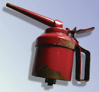
In the last issue Imentioned PCBWayand their metal 3D printing service. Inow have aremarkable litle crosshead forone of my stationary engine modelsonmybench.I will be doing some finish machiningand fiting it to my model in time forthe next issue, watchthis space.
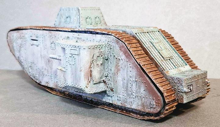
I’ve alsobeen down something of arabbit hole, researching the WW1 GermanA7v tank. Only twentywere made, and asurprising number of photographs as well as military records exist. Eachhas its owndistinguishing features, but, as always, information from the internetisnot to always accurate. Ihavefound acopyofthe second edition of SturmpanzerA7v: First of thePanzers by Strasheim, Rainer and Hundleby. I’vespent much time cross-referencing photosto my ownexcel spreadsheet and the datasheets on individualtanksinthe
book. My initialaim is to design and make aseries of resin-printed models of notable examples, the photo shows my model of the A7Vu variant. I’m increasingly thinking that a1:16 scale model in metal couldbeanexcellent workshop project.
Neil Wyat Editor
Diane Carney Deputy Editor
Neil Wyat
Contents
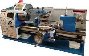
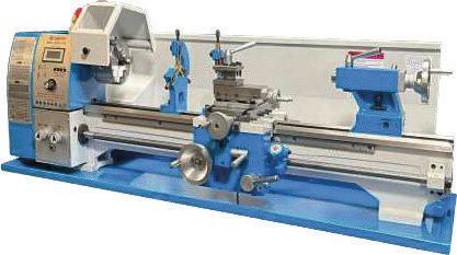
9 CoverStory: Milling in the Lathe It wasonce rare to find milling machines in amateur workshops, RodJenkins has found the skills and equipmentfor milling in the lathe still have theirplace.
14 Meetthe Editor
Following thereunification of two magazines intoone, manyreadersmay be unfamiliarwith Editor,Neil Wyat Here’sabriefoverviewofhis journey in the hobby
17 AGWR Pannier Tank in 31/2" Gauge Gerald Martyn continueshis construction guide with the valvegear.
44 How(Not) to Build aLocomotive for Someone Else.
Jim Woods and JonathanBregazzi conclude their storywith the completion
of 2-4-0Beyer Peacocktank locomotive, Loch.
47 Extrac tin gaB ro ke nStud
To con clude our drillin gc hal le nges, Ala nD onova nm akes ag uid eb ush to assist with ex trac ting as tud from a cylin d er ca stin g.
52 The St at io na ry Steam En gi ne Ro nF itzgerald con tinues his note s on t he earl iest steam locomotives.
54 Making Small Threads
Notd ril ling,b ut stil lo nt he to pic of avoiding breaking delic atetoolin g, Stewa rt Hart sh ares des igns fo rs ome smal le rt apping and threadin gtools .
Your magazine is growing and changing into Model Engineer &Workshop.Find out more and letusknowwhatyou wouldliketosee in the new, larger magazine at: www.model-engineer.co.uk/forums
Visit the forum to download files forDavid Thomas’ beltjoining jig. htps://www.model-engineer.co.uk/787489/belt-joining-jig/
Hottopics on theforum include:
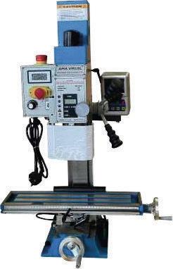
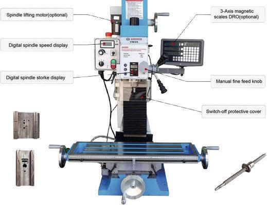
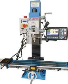
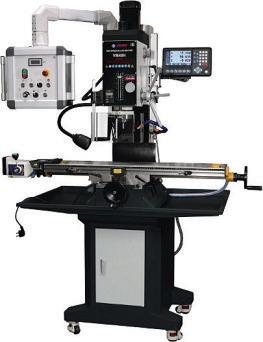
•Warco WM18B CNCconversion started by Tomek. Aneatly executed conversion and some photographs of the results.
•Clarkson Tool and CuterGrinder Operator’sManual started by Derek Toller 1. If youneed amanual foranold machine tool theForum is agreat place to ask forhelp!
•A"Weaver"1CC Diesel Engine started by KeithBeaumont.
Afantastic litle engine and some great machining and anodising work.
As well as plenty of engineering and hobbyrelateddiscussion, we arehappy for forum memberstouse it to shareadvice and support. Come and join us –it’s free to all readers!
On theCover Next Issue
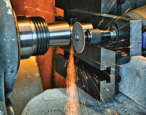
Our coverfeatures the use of arotarytoolwith acutof wheel, alessconventional approach to milling onthe lathe. Read morefromRod Jenkins starting on page 9.
In our next issue, Graham Meek presents his design fora screwcuting clutch to fitthe Emco Compact5 lathe.
Millingin theLathe
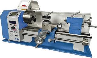
Up until the Millennium,milling machines were nota common sight in our workshops, thereare still many readersthathave only alathe. RodJenkins shares some of hisexperiences.
“Good griefRod, whyon earth would youwantto mill in the lathe,you’vegot aperfectlygood milling machine?” Well, it wasnot always so, but it is agood question.
Ithink it is generally agreedthatif youonly have one machine tool then the mostversatile is the lathe. The addition of avertical slide allows the user to hold acuter in the lathe spindle to achieve somesimple milling tasks, ofen enough to makea small stationary engine or,indeed,those milling tasksrequired to make even a5-inch gaugelocomotive, such as cuting steam ports forslide valves These days asmall millingmachine is available foronly three or four times the costofa good vertical slide and will be infinitely morecapable. Ihave, however, been on ajourneywith lathe milling so perhapsyou cancome with me while Iexplain my obsessionand youcan decide if this is a good answer…
Milling or drilling in the lathe by holding
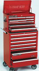
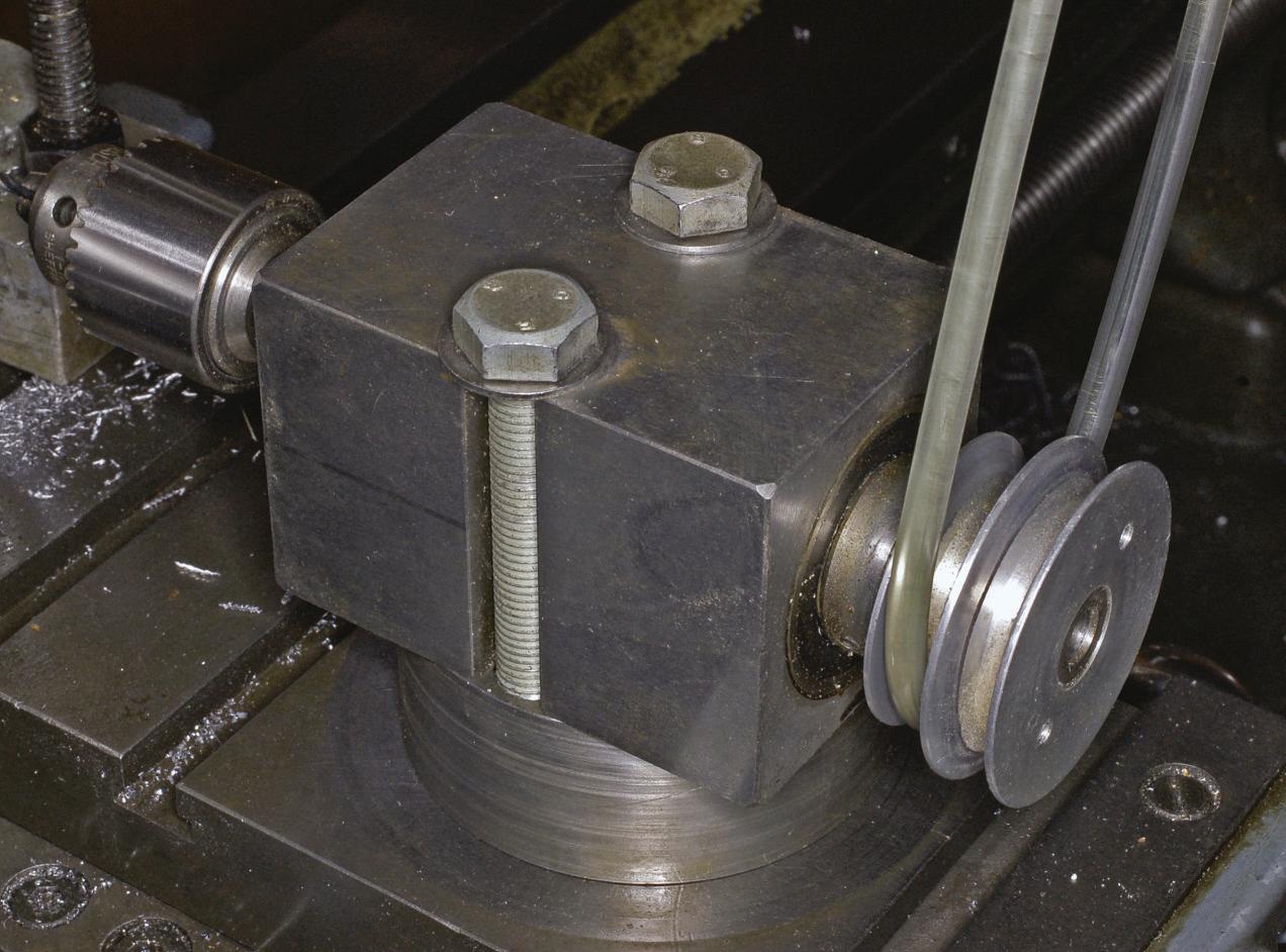
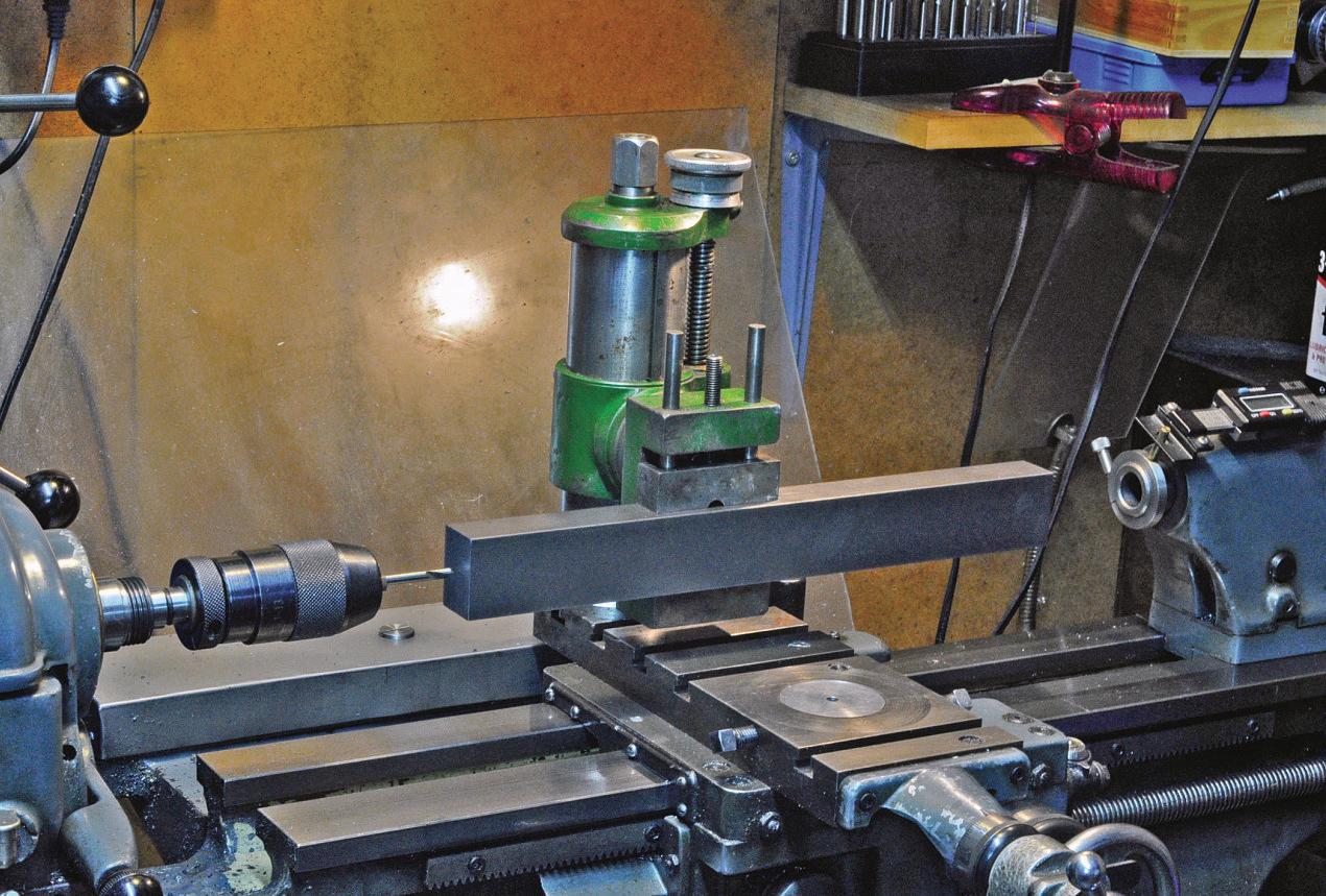
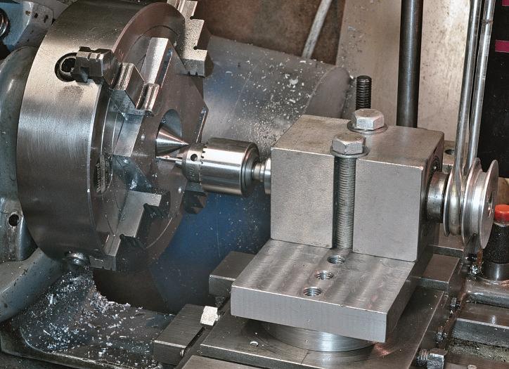
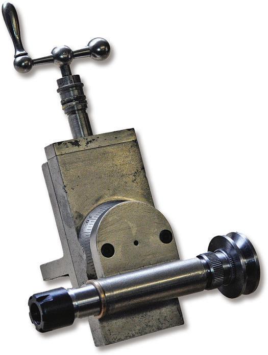
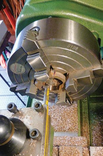
acuter in the chuck andpackingup the job on the crossslide is aprety poor substitutefor apropermilling machineofany size, but it will do the job forsmallitems. Addinga vertical slide greatly enhancesand eases this approach.Insomecases, though, the vertical slide will help oneachieve somethingthatcan’t be doneany otherway,atleast in my workshop Oneproblem thatoccurred wasdrilling holes in the endofa 1.5 x1inchmild steelbar forthe George Thomas bendingrolls. At thirteeninchesthey were fartoo long to fit under the spindle of the mill anditwould have beendificult though (I must add) not impossible to contrivea fitmentover the edgeofthe drill table.The simple solutionwas to fit avertical slide to the lathe crossslide anddrill the holes as shown in photo 1. This slide waspicked up at alocal steamfair for£25 –my thoughts beingthatI woulduse it to modify my Worden tool grinder to have an adjustable heightgrindstone,an idea nowabandoned. This particular
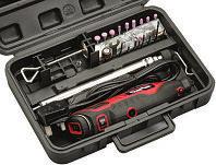
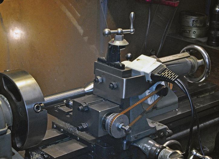
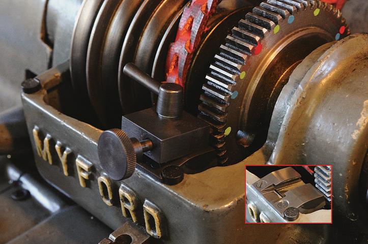
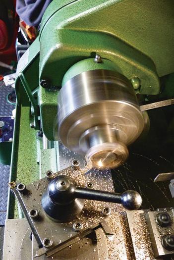
vertical slide is quiteinteresting in thatitisvery similar to the design for the Pots millingspindleversion butis ratherbigger andhas Tbolts thatare sized forfiting the slotsinthe Myford crossslide. Theintegral vice is auseful time saver. Avertical slide can also be useful forholding othertools such as the Dremelshown in photo 2 Amongst the boxofbits thatcame with my second hand MyfordSuper 7lathe were the castingsfor the George Thomas Headstock Dividing Atachment(HDA).This is arefinementonthe design of JARadford thatusesa worm on the bull wheel to turn the lathe into adividing head. Havingmade the HAD, Ihad asophisticatedindexingsystemfor the lathe so Ithoughtitwould be nice to cut my owngearsfor smalli.c.engines. So,if the lathe spindle is doing the dividing work,I wouldneedsomething to turn the millingcuters. Which bringsme to the real pointofthis discourse: The MillingSpindle Readingthe modelengineeringbooks
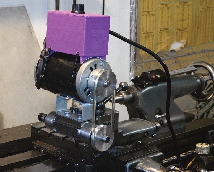
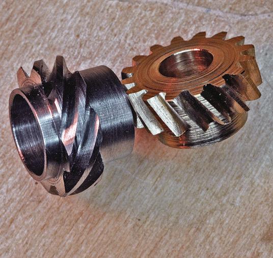
Photo 3: Arrand milling spindle.
from ageneration or twoago there arereferences, with somereverence, to the Pots milling spindle.The Pots wasavailable in severalversions,one of which could be bolted to avertical slide and my lathe came with aMyford
swivellingvertical slide. But the Pots wassadly longout of production. However, at thattime in the 1980s, ArrandEngineeringwereadvertising their waresinthe ModelEngineer magazine andamongst which wastheir
millingspindle. Ipurchasedone of these, photo3,and Iwas pretymuch setupfor gear cuting. Ijustneeded a methodofdriving the spindle. Theconceptofhaving aseparatespindle formillingand drilling on the lathe
Photo 1: Drilling the end of along beam.
Photo 2: Holding aDremel.
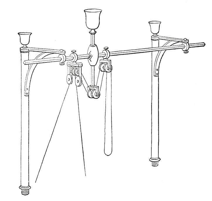
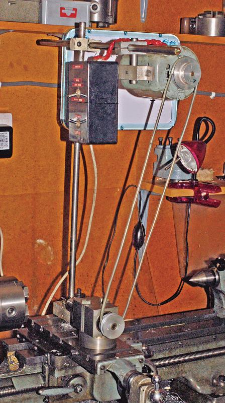
is very old and probably had its genesisonthe early 19th century ornamental turning lathes, such as those made by HoltzapfelorBirch. Some quite complexoverhead drivesystems for these spindles have beendescribed–an example is shown in photo4.The need forthis complication wasdue to the requirementtokeep aleather or cotondrivebelttensioned while allowing movementofthe milling spindle. Fortunately modern polymer drivebelts with somestretch in them and compactelectric motors allowus to use asimpler design. My overhead gear is shown in photo 5.Itconsists of a1/6hp induction motortogetherwith abox thatcontains astartingcapacitor, on/of and reversing switches. The whole thing hangsfromsome½”steel bars connected with old laboratory clamps. Forgear making with homemade carbon steel cutersIcan put a countershafpulley in the system to bring down the cuting speed. One of the problems with my Sharp milling machine is thatitdoeshave restricted headroom.Mounting a chuckonarotary table in order to drill apatern of holes in the face of adisk isn’t astraightforwardoption and the combination takesupmost of the available space. Using amilling spindle in the lathe overcomesthis issue and without having to move the job to the mill. Over the yearsIhave found thatwell over 90%ofdrilling and milling using the spindle on thelathe is done at centreheight.So Imade a fixture forthe milling spindle thatfits into the top-slide hole in the crossslide and, when bolted to the fixture, the milling spindle is at lathecentre height. Depending on howthe spindle is orientatedthis is perfect formilling keywaysand drilling cross holes However, my first design didn’t allow the cuter to getclose enoughtothe centreline of the lathe when parallel to thataxis. Themodifieddesign with severalmounting optionsisshown in photo 6.
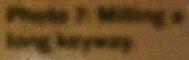
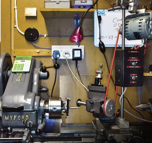
While keeping an eyeonthe internet, Inoticed aMyfordfixed (non-swivelling) verticalslide together with ahome-made millingspindle, thatIrecognised as an Arrand, being ofered by one of the well-known model engineering suppliersand whichI wonfor acheeky bid. My thoughtwas thatthe slide and spindle could allbemotorised in one package, thatcould be quickly installed on the lathe cross slide instead of the top slide and would avoid havingtoset up the overhead drivegear.The spindle is driven by a120 Watsewing machine motorand the twoare mounted together on the verticalslide with abit
of bent3/32inchsteel plate, photo 7.Myslide doesnot have azero-able indexonthe leadscrew which actually turns outtobeanadvantage since Iknowthe readingfor the centre line of the spindle to be on the lathe centrelineand Ihavemarked this with ared line. TheMyfordslide is designed to be fited to the Myford Super 7 cross slide either with 2bolts straddling apair of Tslots or with both bolts in thesameslotsothatthe face of the slide is either perpendicular or parallel to the lathe axis.I have an ER111MT collet chuckmounted in the Arrand spindle anda setof1 to 7mmcollets in 0.5mmsteps.With this configuration, notonly can Idrill or mill items held in the lathe chuckI can,byrotating the slide 90°,drill across hole or mill akey waydownthe length of ashaf. The sewing machinemotor will cope with milling cuters up to ¼”/6mm or will drilluptosimilar diameters although it does prefer to have apilotholefor drilling holes largerthan3/16inchor 4.5mminsteel
Some yearsago,amillingspindle with anintegrated motor, the Payne Quick-Step, became available. This device couldbemounted on atoolpost,evenaquick-change tool-post, but the cost wasthe priceofa new milling machine! Always on the lookout foraneasier setupand an excuse to makemoretooling Iwas atracted to
Photo 4: Victorian overhead drive
Photo 5: Overhead gear.
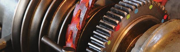
the conceptand contrived something similar formyself.The Quick-Stephad abuilt-in movement in the vertical axis but, as stated, Irarely need this capability.Onmyversion Ihaveused an ER11colletchuckwith a12mm plain shankmountedbetween apair of angular contactbearings in asteel body.These plain shank colletchucks areprety tough, andI had to anneal the endbeforeIcouldcut afine thread forthe endfloatadjustmentnut. The spindle body hasa flatmilled on either side so thatitcan be atached to aMyford-Dickson quick change tool-holder whichallowsprecise heightadjustmenttothe lathe axis. Themotor is a200W DC unit bought togetherwith an accompanying AC/DC converter andspeed control, photo8. TheMyfordSuper 7lathe lends itself to direct indexingonthe lathe spindle becausethe bullwheel, which is used when utilising back gear but is normally locked to the spindle, has 60 teeth; this gives many options for direct dividing by using aspringloaded detent to locate in the gapbetween the gear teeth. Usingthis method 2,3,4,5,6,10 andmoredivisions are available. Onenotable and sometimes needed exception is eight divisions since 60÷8 is 7.5teeth foreach division. This can be overcome by having adetentwith anotch in it, thatcan be rotatedtostraddle agear toothaswell as the toothgap.Myversionofthe bull wheel detent is shownin photo9 and is closely based on adesign by Harold Hall. Ihavemodified Harold’sdesign to giveaquickrelease and setcapability by havingapermanentmount on the lathe into which the detent device can be quicklylocated. Together,the tool postmounted milling spindle andbullwheel indexerlet me rapidly setupfor mostofmymilling in the lathe requirements.
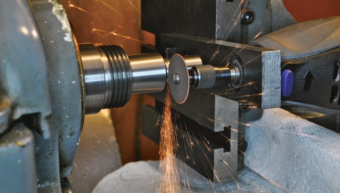
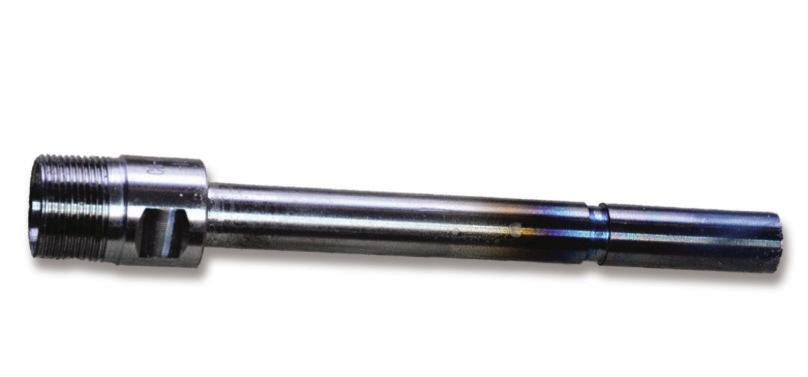
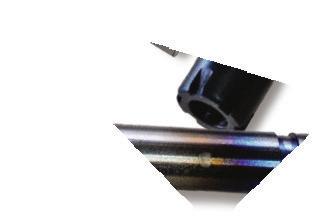
At this pointthe reader will have noticed thatIhavemorevertical slides thanany sane person should possess but, actually,thereisone more. Photo10 showsaLorch verticalslide thatIrefurbished and fited with amillingspindle foruse on my Pultralathe.This spindleismade from an 8mmstraightshank ER11chuck. Photo11 showsthe spindle with the heat afectedregionresulting from the annealI hadtodotocut the threads. In this case the bearingsare Oilite, pressedintothe housing. WhenI hada go at making Edgar T. Westbury’s Wyvern open crank engine, Iwantedtomakethe gears myself.These helical gearsdrivethe sideshafwhich controls the cams andtherefore include a2:1 ratio.ETW’s design callsfor gearsofthe same diameter, anot immediately obvious
Photo7:Millinga long keyway
Photo 8: Tool post spindle.
Photo 6: Arrand spindle on centreheight mount.
solution thatrelies on the phenomenon thata pair of helicalgears at right angles will mesh if their helix angles add up to 90°. Thediameterofhelical gearsofthe same DiametricalPitch (or MOD)isdependentonthe helix angle so by choosing the correctangles the same diameterefect canbeachieved The“magic angles”togivea right-angledrive, for8 and 16 toothgears respectively are63.4° and26.6°, in this case. To makethese Ihad to go back to my basic milling setupinthe lathe forusing Brown&Sharpe typegear cuters.The milling spindle wasset up at the helix angle on the swivelling vertical slide, the lathe change-wheels (and gear box) were settogivethe correct lead, and the overheadgear drove the spindle. Thelathe carriage wasdriven by the lead-screw handwheel to rotate the gear blank under the cuter as it travelled towardsthe head-stockfor eachtooth, photo 12.The finished gearsare shown in photo 13
That is my milling spindle journey to date.Ifyou’vetravelled this farwith me; Ihope Ihavegiven someideas forwaystouse amilling spindle in the lathe. Second hand spindles likethe Pots or Arrand do turn up forsaleon the webfromtime to time,and Isee thatthe Sherline catalogueincludes aNo1 Morsetaperheadstockwhich would seem to makea very nice milling spindle. Thereare,ofcourse,many small routing type motorised spindles available forthe CNC community in all sorts of sizes. Ihavenoexperienceof these, but my fear is thattheir design speed is rather toofastfor thesort of work Ihavedescribed and thatthey will have insuficienttorque when sloweddowntoperhaps200rpm if used forgear cuting
Readers of Model Engineermay be less familiar with former
Model Engineers’ Workshop editor, Neil Wyat.
Meet the Editor
ito
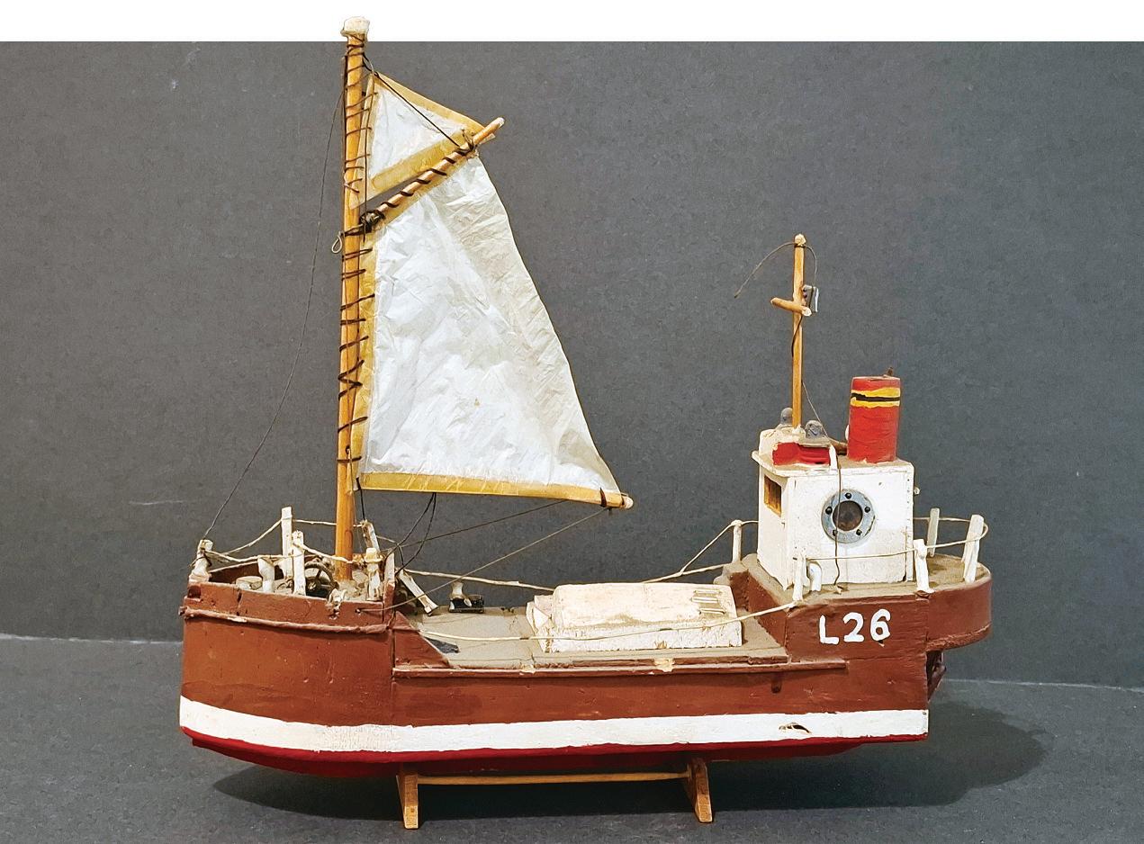
Ican’tremember atimewhen Iwas notmaking models of somesort or other.Igrewupwith Meccano (mostly passed down from my Dad) and Lego, and graduatedtoAirfix kits as soon as Icould be trusted withamodelling knife. In my childhood, Dad had the entire ‘middle room’asa workshop and it was full of radio controlaeroplanes,boatsand accessories. My equivalentofProust’s madeleines is the smell of nitrocellulose dopeand castor oil. It wasimpossible nottobecome modeller in suchan environment,and my interests expanded tomodel boats, and Istill have acrude balsawood Clyde Pufer that Iremember proudly taking to Junior school to give atalkinfront of my classmates, photo 1.Another talkwas on the principles of flight, aided by an aerofoil cross section from one of Dad’scrashes. Eventually Dad’sworkshop ended up in ashed, then a big garage andhis interests movedto very large model boats. Somehow, Iwas allowedtomakea small conservatory intoa workshop,inwhichIplayedradio controlboats, electronics, basic metal bashingand, ahem,a fewpyrotechnics… Iread the odd copyofModelEngineer
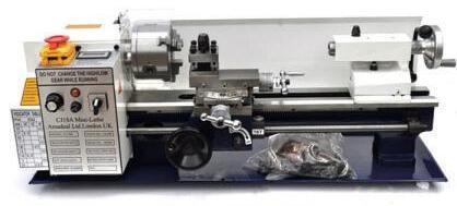
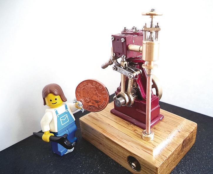
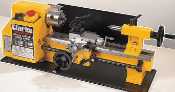
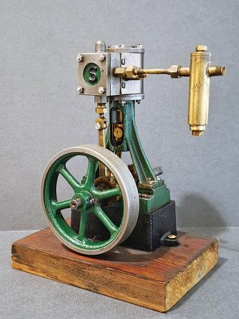
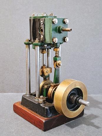
thatsnuck in alongside the usual fare of Model Boats, Aeromodeller and, ofcourse, Military Modelling.The work Isaw in ME seemed totally beyond whatIcould do,unfamiliar with power tools beyond ahanddrill. Career wise, my ambition wastobeanengineer –specifically,anair accidentinvestigator forthe RoyalAircraf Establishmentin Farnborough. Possibly seeing so many crashed model aircrafwas an influence? It wasnot to be, Ifollowedacareer that sawmebecomeaChartered Environmentalist, including twenty-fiveyears working with the WildlifeTrusts. Along the way, in my late 30s, Iwas able to establish my firstengineering workshop This wascentred around aClarkeCLM 300 mini lathe.Myfirst majorproject was, aStuart Turner (now Stuart Models) 10V Itran well, although perhaps it deserves a beterbase, photo 2.Asecond stationary steam engine, from Reeves 2000 castingswas the EdgarT.Westbury Trojan, photo3
Ifound making accessories and modifying my equipmentwas as satisfying as making models, which led to aseries on‘TheMini Lathe’inModel Engineer
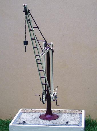
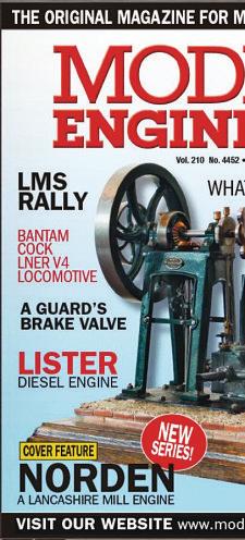
followedbyshorter articles on modifications to the long-sufering machine, photo4.Thereare thirty items on my incomplete listofmodifications! It wasonly when twoofmymodels made it into the pages of Model Engineer,thatI felt Ihad finally ‘made it’.The first wasmymodel of the Fradley Canal Crane, photo5.I considermystationery engine Norden, photos 6and 7,built
Photo 1: Abalsa Clyde Pufer, made when aboy
from asketchinanold issue of ME to be my bestmodel. Ihad castingsmade frommyown paterns, and Ihaveseen afew models made to my design,which is very satisfying.Ilater discoveredthat it is aChadwick engine, and one significanterror wasfollowing the oldsketch inataching the slide barstothe cylinder not the frame.
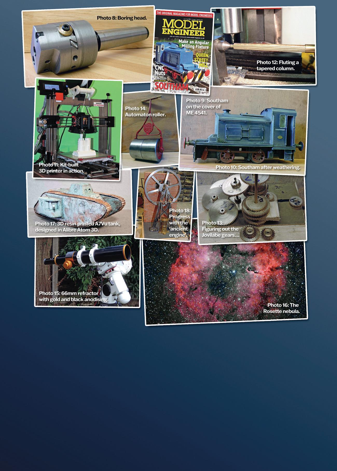
Ilater had some articles, notably aquick changetoolpostand improvements to my X2 mill, in ModelEngineers’ Workshop.In2014,I took on the role of editing MEW, from issue 215. Likemypredecessors, thatled to quitealot of my own work being writen up ofen to cover missing topics, such as my boring head, photo 8,and aseries on Lathework for beginners
Iwas still thrilled when my 3½”gauge diesel outline electric shunter, Southam, appeared in Model Engineer, photo9 Ilater weathered it, and personally think
Photo 4: Much modified minilathe, in alater incarnation.
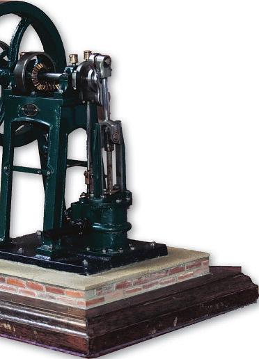
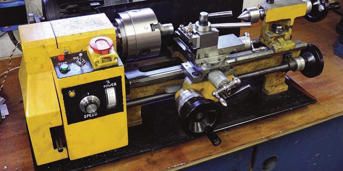
it looksmuch less toy-like, photo10. In 2017,I wasasked to trial and review aDremel 3D printer, and this opened a whole newworld of modelling forme. If nothing else, it led to me developing my skills in 3D CAD. Istill find the waythat 3Dprintedmodels appear out of almost nothing quitefascinating, photo 11 I’vecontinued to work on avariety ofmodels, and my workshop now boasts an SC4 lathe, and is quitewell equipped. Iam, very slowly,moving forwardwith Tubal Cain’s (Tom Walshaw) Lady Stephanie beam engine, photo 12, but my stationary engine fascination got taken over by another designfromanold engraving of an ‘ancientengine’. Aminor obsession with gear cuting found memaking manyparts fora Jovilabe, photo 13.Completion of this ambitious mechanism is dependentonmefinding a satisfactory waytocut and engrave a
gear some teninches in diameter.A less ambitious but very satisfying project was a miniatureRansomeSimms and Jefries Automatonlawnroller, photo 14. One, morerecent, completedproject wasa telescope specifically designed for astrophotography, photo 15.Built aroundacommercial lens cell, it includesaCrawfordfocuser with a 10:1 epicyclic speed reducer.Aspart of constructing the scope, Ihad to delve intothe dark arts of anodising,with surprising success. Thescope proved tobeexcellentfor astrophotography, photo16,(one of my other hobbies, along with playing bass guitar).The scope wonanunexpected silver medal at the NationalModel Engineering Exhibitionin2019.
In 2020,Imoved in with my fatherand although I’vebuilt anew workshop, various thingsmeant Ihavenot been as activeasI would likefor awhile.Over this time, designing scale models in AlibreAtomand 3D printing themhas provena lifeline, photo 17.Sadlymy Dad,the inspiration and encouragement formymodelling hobbies,passedaway late in 2024.The ironyisthatI will now havemoreworkshop time, but another changeofworkshop is likelytobeinthe ofing.Nonetheless, Ihopetocomplete my ‘ancientengine’overthe next few months, photo 18.Ihope youhave enjoyedthis briefreviewofmymodelling interests as much as Iappreciate leters andphotographs from readerssharing their achievements.
Gerald Martyn builds a locomotive he canlif, continuedfromModel Engineer issue 4761.
AGWR PannierTank in 3½InchGauge
ValveGear
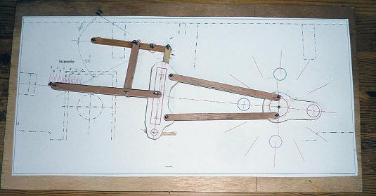
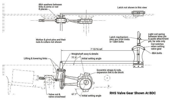
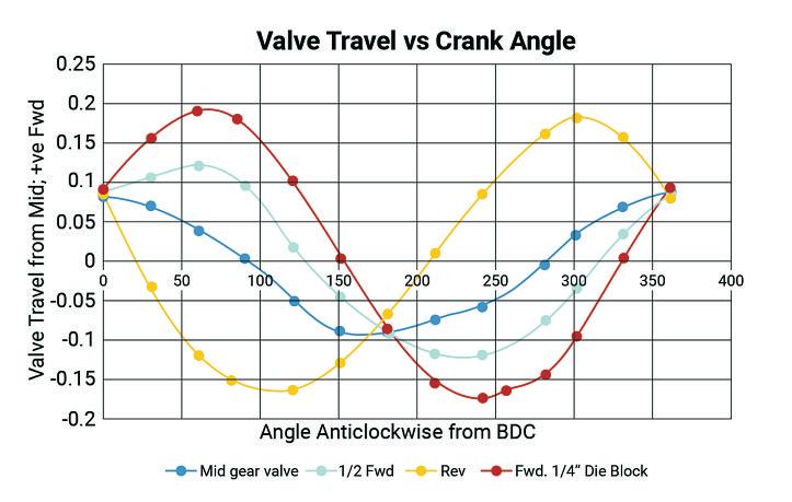
The valvegear is Allan straightlink type andfollows the full-size layout in mostrespects. The general arrangement drawing is shown in fig. 26.The model valve gear difersfromthe original in some notable respects. As youalready know, the valveproportions come straight from RobRoy,soport opening is 3/32”, lap is 3/32”,and we need atotal valve travel of 3/8” whichissomewhat over scale. Alaunch type expansion link is used to achieve this travel withouttoo much angularity in the link and much bigger eccentrics. Aslight change, too, is that the lowering links areasa pair, likethe lifinglinks,rather than one on centreline as per the original.This is beterfor lateral stabilityand forlaser cuting.I’vedonea bit of work to get agood design, with atwice full-size model foraid, photo 72.This wasused to produce thevalvemotions shownin fig.27.Infull gear this is areasonable sine waveform and stays pretygood as it’snotched-up. Steam inlet occurs close to the required topdead centre
points in all gears, and cutofisconsistent. We neverseem to lookatwhen the steam is released to exhaust, just the openings on the pressureside.With this gear the steam cut-ofinfull gear is 75% pistontravel, about as expectedbut the exhaust port opens at 87% so the much-vaunted expansionisjust 12% At 55% cut-of the expansionimproves to around 25%travel(and 31% by steam volume),but release comes forwardto 80%. At the release point the exhaust closes at the other end so what is lef in that end of the cylinder is nowbeing compressed. These things areinherent in anyvalvegear with sinusoidalmotion and forany given valvetravelcan only be changed by altering the valveorports. Theblue line in the middling height area is drawnfor mid-gear and is the sum of the eccentric ofsetfrom90º and
the shif caused by diference in the angularity of the rods in crank forward and crank af eccentric positions. This is roughly equal to twicethe valvelap,as it should be, and is the equivalent of the more easily understood motion from the combination leverinWalschaerts’ gear.I’m no valvegear expert, by the way. Theabove observations come
from my reviewofthe motion generated by this gear and the efect it has onsteam inletand release. Ifound the plotedwaveformsfar easier to interpret than the sort of valveevents diagrams published in bookswhich are, in any case, aderivation of these.
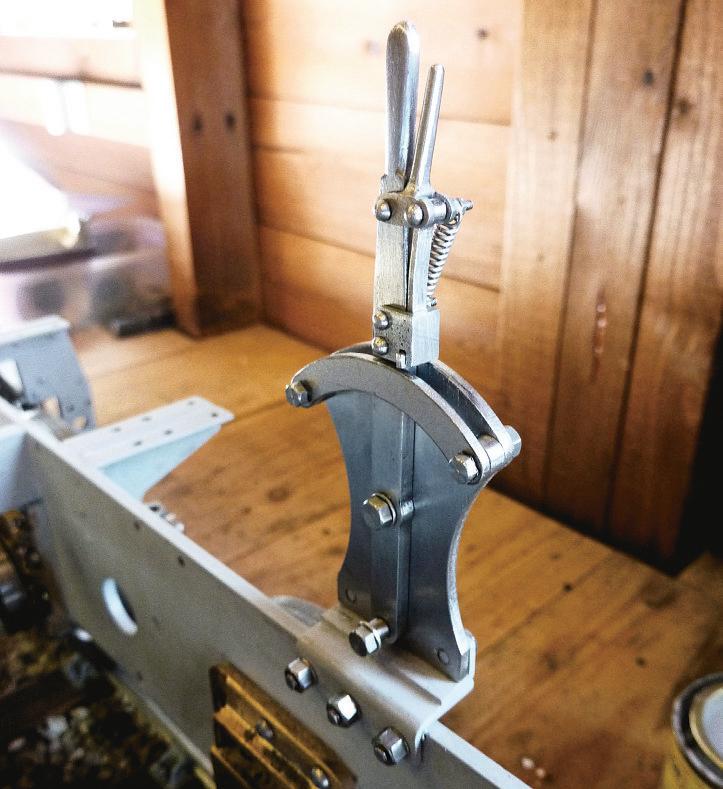
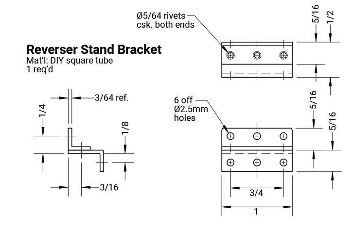
On with thejob.The gear makes full use of laser cut parts, with waterjet cuting used forthe expansion link. Thereverser is agood place to start, anditrepresents highly visible progress whencomplete.The stand is ofset rightwards on alitle bracket made from twopieces of that DIY shop square tube previously purchased, fig. 28.The rivetsholdingthe twopieces together need to be countersunk on both faces of the joint, and of course countersunk
bolted to the mounting bracket, and herethe bolts must be cut of flushon the inside face. Forthe sector twolitle spacersare needed and remember the bit about tolerances; these should be justa bit thicker than the reverser lever to allowittowork freely.The levercan nowbetried in positionand thesector bolted on with the spacersbetween using 8BAnuts and bolts. Note that quadrant notches should notbecut until valveseting time.
rivetsare on the unobtainium parts and materialslist. Just clip alength from the shank of adomehead rivetand bash it down intothe countersunk holes at both ends. File of flush. Ireinforced with alitle sofsolder forluck. My angle had asmall internal corner radius so to fit it neatly and squareonthe frames then asmall chamfer on the frame edgewas needed. Thedrawings forthe reverser components are fig. 29.The laser cut parts just need cleaning up and some holes sorting out. Thepivot pins aresimple turning and canbefited, one in the stand and one in the lever, with Loctite and peened over intosmall countersinks. Theone in the botomof the reversing levermust be filed flush on the rear face. Thestand cannow be
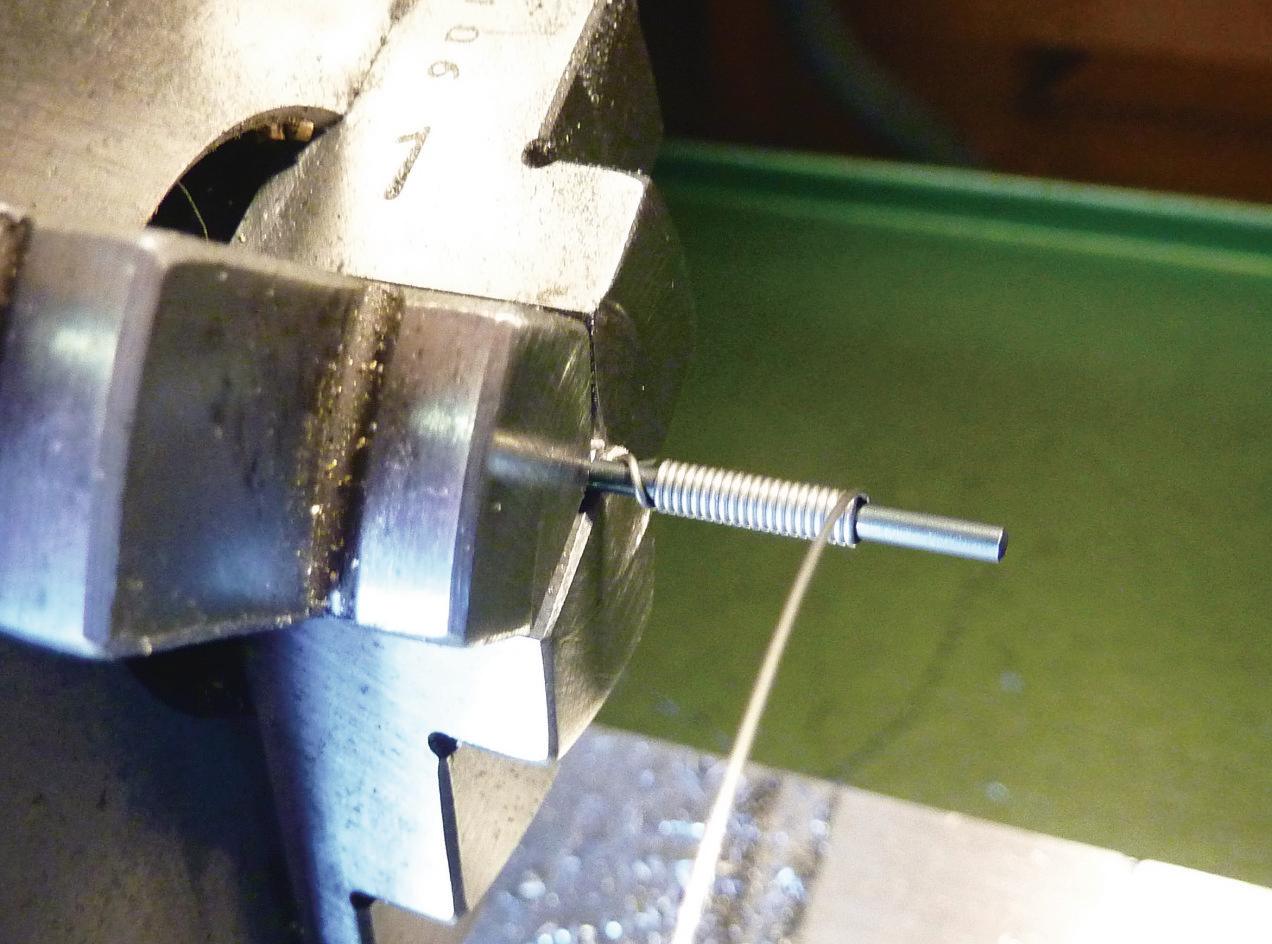
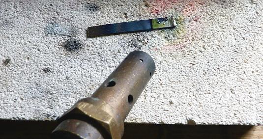
Afer thisrapid progress thelatch mechanism is abit of ashock. Not exactly watchmaking but close, and mostly hand tools areused. Theguide block is cut from 3/16”x anywidth mild steel bar.The trigger,too,comes from 3/16” bar.Notethereare slotstomake afork at each end of the base section, with anarrow uncut section between. Without thisthen there’sprecious litle holding the leverarm piece on. My method wastomark-out the profile, drill the holes, including twotoform the radii to the arm,then carefully saw out and file to shape. Slotthe forks and finish by thinning and rounding the leverarm.The latch blade is madefrom apiece of 0.9mmsheet, withasmall turned and drilled hingetube silver soldered on, before cuting to shape. This soldering is justdone on afirebrick with no holding required. Thefluxwill pushthe bits apart but as it melts push them back together with apointy steel scratching rodand then thesurface tension in the solder willhelppull them intoclose alignment photo 73.Try not to getsolder in the hole!The latchcan then be carefully cuttofit;the dimensions arefor guidanceonly in this case. Theassembly can be done with3/64” rivets, or 3/64” rivetsthreaded 12BAor it will be found that 12BAbolts canbe justtapped through with litle lossof thread, and nuts canthen be put on the back. One on the leverand one on the guide block mustbelef longtocarry the spring.For thislater Iused 27 SWG stainless wirewound round adrillshank, photo 74.Thinner wirewould have been beterbut that wasthe best Ihad There’snomystery to making this sort of light duty spring.Wind wireround arod, pull it out abit, trim to length and bend
Photo 72:Valve gear model
Photo 73: Soldering the reverser latch.
Photo 75:Finished and assembledreverser
just fit in the width, and Ifound that 8BA washersfited well toowithout anyextra work.Ifthe hole is notpositioned quite right and the bolt head overhangsthe edgeofthe eccentricjust abit,then don’t panic. Theother sidewillbeOK and so long as the OK sides face each other on each eccentricpair on the engine then no scoring of theadjacent eccentricwill occur
With the strap in the 4-jawchuck, with the already faced side running square and the hole centred as faraspossible, then borethe hole to size, photo 77.Toturn the eccentrics to thickness, asimple mandrel canbemade, just a couple or three thou oversizeondiameter, photo 78.Aferuse and without removing from the chuck,then skim the mandrel down to eccentric diameter, drill and ream fora centrelocation pin, and part it of.This will be used on the jig whichisessential when joining the rods to the straps to getthem allthe same length. My parting-ofworkedfine this time, by the way! Thestrap outer profile need notbeterribly accurateand is best done with hand tools. Those files kept foruse on brass will have themetal of quicker than youcan say'rotary table and special fixtures', and theolderones used forsteel notmuch longer.
the end coils up into loops. Thefinished reverser is shown in photo 75
Thereach rod, is along thinlaser cut part which mayneed straightening and then just aclean-upand ream the holes 1/8” diameter. Done in minutes, and so obvious I’venot shown the drawing. If straightening, then youmay notice howeasily therod can be bent. The material is CR4steel, theysay.Ithas a yield strength(when it starts to bend) of less than 210 MPa, or about 30,000 lbf/in2.Areasonable aluminium alloy would have ayield strength around 500 MPa(at one thirdthe weight), and amid-grade steel foraerospace use around 880 MPa. Steel has an amazingrangeofproperties. In our case CR4isuseful stuffor cuting,shaping and forming,but something beter is needed forhigh strength or high
wear applications.
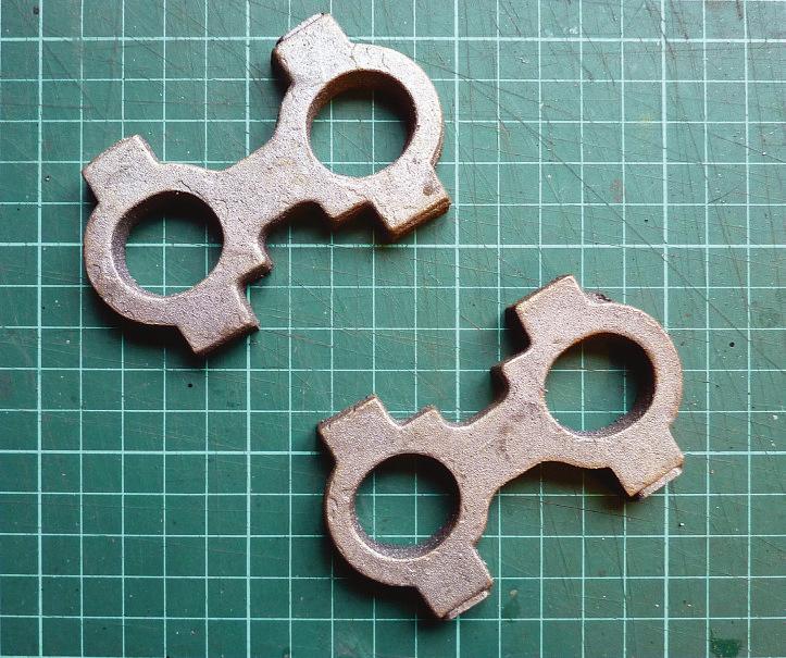
Thedrawings forthe eccentric straps androds and forthe valverodsare fig. 30.I started with the straps, which use the RobRoy castings and aresimilar exceptthe thickness is reduced to 3/16”, which reduces the rodofsetand is a value used by LBSC formodels this size, and the bolts aremoved apart slightly to improve clearances. It should be possible to sitthe bolt heads down flat without resorting to spotfacing My castings cameastwo pairs, photo 76,and Istarted by milling the topand botomedges to near sizetoget some metal of and createadecent datum. Split intosingle straps and popeachin the 4-jaw chuck on the lathe to clean up one face. Therest is much as previously describedfor RobRoy.The 7BAbolts with one sizesmaller8BA heads will
Ways of making eccentric rods arediverse. In the RobRoy book it is proposed to machine from solid, but there’salot of metal fora smallmachine to remove.Laser cut to profilethen machine would makeiteasier but, as we nowknow, in thickmaterial theprofile will comeoversize, so it also needs filing all around. My methodissilversoldered fabrication. Forthis modelthereare laser cut shapes which reduce the efort. Theparts arethe rod, which has ahole at the eyeend just forlocating the other parts, twospacersand two eyeends (lugs), and theycan be loosely assembled with a3/32” and a1/16” rivet. The3/32”one through theeye end needs to comeout aferwards,so should be well oxidised and coatedwith typing correction fluid to discourage the solder from ataching,but the1/16” one needs to be cleaned and soldered in properly.Flux the jointsupwelland arrangeona firebrick forsoldering with Silveflo 55 or similar.When thesolder runs through then gently close the joints up with pliersorforceps, photo 79,and allowtocool.
Remove the 3/32” rivet and check things out and then cutout thecentre locating eye(piercing saw).Ifthe fork ends arenot quiteright then in this rather sofapology forsteel it’s easyto correct. When drilling and reaming the eyeend holes, careisneeded as there’s notmuch sparemetal. Theone Idid while holding the job by hand didn’t work toowell. Photograph80 shows
Photo 76:Eccentrics straps castings
abeter way. My fork eyeends were reduced to 7/32” diameterand though this should be strongenough thereis litle marginfor error.One slip of the fileand all is lost. Forthe final design, then, Ialtered theoverall geometry slightlytoallow¼”diametereyeshere and at thevalverod. Photograph 81 shows my finished eccentric rods.
Ilef the slotinthe front of the eccentric straps until Iwas sureofthe thickness of the rods, and then didthe cuting by repeated plunging to full depth with a3/32” slotdrill before finally skimming to width. Thedepth is just withinthe limits of astandardcuter. Therods areone sizefitsall as the bent ones needtostart out slightly longer than the flat to allowfor the bending So,some metal will need filing of the spade end to getthe finished length justright, and this should be done in conjunction with ajig to getthem all the same length, photo 82.Myjig hasbeen used afew times and the bush inthe topright of thepicturewas formylast5” gaugeengine usingthe same fork-end pinasthis time. Thebent rodiseasyto do in this steel, providedapacker is put between the fork end eyes so they’re notsquished. As abreak with tradition,I fixed my rods to the straps using only Loctite603. This mayseem chancy, but calculated strength of the joint is around 600 lbfsoshould be adequate. I’ll letyou know when theyfall apart.
Thevalverods aremade in muchthe same wayasthe eccentric rods except that, because the packersare so small, thereare litle side extension pieces to takealocating rivet that ensures alignment. These arecut of afer soldering Thevalvecrossheadis made from ¼” or 6mm squarebar and looksnicer if theshank is turned to circular with just aslight lip at thefront end, as shown, but this is notessential. Thecrosshead screwsagainst ashoulder on the valve rodand should be fixed with adab of Loctite, alongwith the valvenut, on final assembly
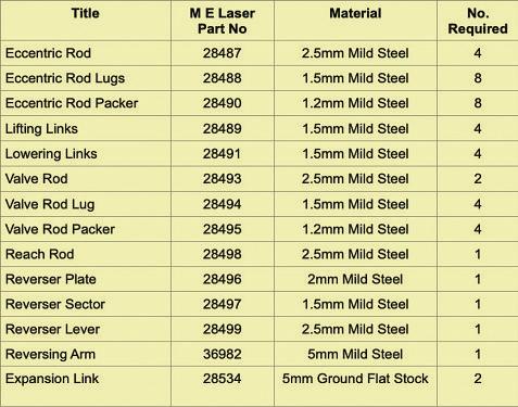
Theexpansion linksshould be made from gaugeplate, forwear resistance. They areavailable from Model EngineersLaser as rathersuper waterjet cut parts, but these come at aprice andthe 5mmthick metric steel will need reducingjust abit in order to fit. Forthese reasons I’veprovided afully dimensioneddrawing so youcan make at home if youwish, fig. 31.Ineither casethe holes need to be reamed and the slotcarefully finished to sizeand made nice andsmooth, forwhich a clean-up allowanceismade in the water jetcut part. It’sinteresting that our usual suppliersonly ofer imperial sizes of gaugeplate, whilst Model Engineers Laser only metric. Hence retaining an Imperial thickness, as 5mm can be