
32 minute read
Where extrusion and industry
from MPN EU Issue 53
by MPN Magazine
WHERE EXTRUSION AND INDUSTRY 4.0 MEET
CHRISTIAN HERRILD, DIRECTOR OF GROWTH STRATEGIES FOR MANUFACTURER TEEL PLASTICS, EXPLAINS THE POTENTIAL OF INDUSTRY 4.0 WITHIN THE EXTRUSION PROCESS.
It’s no surprise that the advent of interconnected devices and advanced computing are affecting common manufacturing processes like extrusion. This shift has been going on in extrusion for longer than most people realise, driven by the demanding medical device market. Automatic online gauges with limited feedback loops have been common for more than twenty years, however, most of these devices still required significant operator interaction and were only capable of simple adjustments to correct for one variable. This is no longer the case.
New extruders typically have Human Machine Interface (HMI) control units in addition to Programmable Logic Controllers (PLCs) that are able to digitally control multiple variables on the machine simultaneously. They are generally capable of network connectivity and can send and receive data with proper IT integration. The same is true for the other pieces of equipment typically on an extrusion line. With a sufficiently skilled IT department, it is possible to log this data, analyse it, and transmit instructions both back to the equipment it originated from and to other equipment on the same line - the critical step to take an automatic feedback line and transform into an industry 4.0 capable line.
There is still no standardised language from PLCs, which creates the need for an integration program that can talk the language of each piece of equipment on the line. This data then needs to be translated into a format that is capable of analysis by both software and recognition by the HMIs human beings use to control the system.
Once the data is translated and aggregated, software needs to be able to analyse and direct the data. This information can be further mined with proper analytics to go from reaction to prediction. However, moving from reaction to prediction requires significantly more computing power and a better understanding of the process. Unfortunately, there is no off-the-shelf solution for this type of data analysis and integration which leads to further issues in validation of software controls and tracking as updates are released.
Taking a sample case from our factory, we have a line with online OD and ID measurement and a fully network capable extruder, blender, puller, and cutter. The line is capable of tracking material usage and automatically issuing material as it is consumed. It is also capable of varying the screw speed or the puller, depending on the product, to maintain the target for the OD and wall. This same measurement information can then be sent electronically to populate a Certificate of Analysis for the product, showing the customer the product meets quality requirements without the need for secondary measurement by operators or technicians. This level of interconnection allows an extrusion process to run with very little operator interaction – but even with this level of sophistication, there is more that can be done.
Additional sensors added to lines can control and predict things beyond the ordinary running conditions. The sensors can translate data into a targeted preventative maintenance system instead of using run hours or calendar days to approximate when failure is likely to occur. They can also send a signal to alert an operator when more material is needed as part of a scheduled delivery, instead of just turning on a light.
It is important to understand that industry 4.0 is more of a journey than a check-the-box upgrade or option package for equipment. You can’t buy an industry 4.0 line off-the-shelf because of the amount of integration needed both between difference pieces of equipment and with things not on the extrusion line.
The future is integrated, and it will be full of information that will make parts both less expensive and more reliable. That is where extrusion and industry 4.0 meet.
Extrusion with high consistency rubber silicone: What to consider
JOHN FREEDMAN, BUSINESS UNIT DIRECTOR, BIOMATERIALS, AND ALEX SANTAYANA, APPLICATION ENGINEER, BOTH FROM NUSIL – PART OF AVANTOR, EXPLAINS IMPORTANT FACTORS TO CONSIDER WHEN USING HIGH CONSISTENCY RUBBER (HCR) SILICONE IN MEDICAL DEVICE EXTRUSION PROCESSES. H CR silicone is a versatile material with a long history of use in medical devices and other industries. Used to fabricate various articles, such as tubing, balloons, sheeting and moulded parts, HCRs consist of a high-molecular-weight polymer combined with silica to produce a silicone that has a clay-like consistency in its uncured form. Medical device manufacturers often choose HCR because of its demonstrated biocompatibility, various processing techniques and excellent physical properties. When compared to other silicones, one of the most unique properties of HCRs is ‘green strength.’ Uncured HCRs can be shaped into a given dimension or form and will hold that shape until cured. In addition, due to their relatively low overall cost, HCRs provide an excellent material for low-volume devices or parts production, using different fabrication methods, such as calendaring, compression or transfer moulding and extrusion. HCRS IN EXTRUSION PROCESSES: KEY CONSIDERATIONS Tubing for catheters and other medical devices are the most common products produced via HCR extrusion, although extrusion can also be used to produce forms, such as ribbon and rod. HCR silicone parts produced through extrusion can have wall thicknesses ranging from less than 0.01 inches up to three inches. Extruded HCR offers a wide range of elastomeric performance, with most having a durometer in the range of 30 to 80 type A. There are several factors to consider when extruding medical device components using HCRs. The first has to do with curing the HCR - the process by which the gum-like, rubbery material is formed and hardened into a final shape. Obviously, the material needs to remain soft enough to be extruded through a die, so curing occurs after extrusion. catalysed curing systems. They can be supplied either catalysed, where the catalyst is included, or uncatalysed, where the catalyst is sold separately and requires combining prior to extrusion. A key advantage of peroxide-catalysed systems is that their curing mechanism is not initiated until the HCR is exposed to heat. This translates into a very long work time which is beneficial for moulding or extrusion. It should be noted that peroxide-catalysed systems often require a post-curing process to remove residual byproducts. Platinum-catalysed systems typically consist of two components: One contains the platinum catalyst, and the other contains hydride functional crosslinkers and cure inhibitors. When combined, the HCR retains its pre-cure consistency for one to two hours and no undesirable byproducts are produced in the curing process. A key advantage of platinum-catalysed HCRs is the ability to heataccelerate the cure for increased throughput. Before extrusion, HCRs need to be processed with a two-roll mill to soften the material and to blend two-part systems. This also modifies its consistency so it can flow more easily through the die. This processing step, as well as extrusion itself, generates heat; if too much heat is generated, the HCR can begin to cure, so it is common for this equipment and processing area to be cooled to prevent curing prior to or during extrusion. Once the HCR has been milled, it is fed into the extruder. Extrusion is a steadystate process designed to continually produce a high volume of finished parts with the exact same dimensions and properties. Many extrusion systems use a screw mechanism to force the HCR through the die since this provides a highly controllable feed system. This is important to ensure uniform production of the finished extrusion and to control factors like wall thickness. After extrusion, the HCR parts need to be vulcanised or heat cured. WORKING WITH HCR SUPPLIERS Since no two medical devices or extrusion processes are exactly the same, silicone providers will have solutions that provide greater flexibility for the manufacturing process. Suppliers with robust-quality systems and ISO 9001 certification, deep knowledge of ISO 13485 quality requirements for medical systems and experience with the U.S. Food and Drug Administration (FDA) MAster File submissions (MAFs) can help ensure that the medical devices you produce using HCRs can be more easily and readily supplied to the marketplace.
High consistency rubber silicone is a versatile material with a long history of use in medical devices and other industries.
24 ADHESIVES
A RACE AGAINST THE CLOCK
PETER SWANSON, MANAGING DIRECTOR OF ADHESIVES SPECIALIST INTERTRONICS, EXPLAINS TIME-BASED CONSIDERATIONS WHEN WORKING WITH ADHESIVES IN MEDICAL DEVICE APPLICATIONS.
There are numerous considerations when specifying an adhesive for medical devices. In a demanding industry, manufacturers are looking for an adhesive that is compliant (often satisfying biocompatibility requirements evidenced by ISO 10993), bonds well to the substrates, and meets other functional requirements of the application. However, there are also time-based considerations at play.
SHELF LIFE The shelf life of an adhesive is the length of time from the date of manufacture during which the material is under warranty to behave according to the technical data sheet, assuming the storage conditions have been met. It often appears on the label as the expiry date - referring to the date that the shelf life ends - or as a manufactured date. If the data sheet lists a manufactured date, you can find the shelf life and calculate the expiry date.
An adhesive that remains unused in the original packaging and has been stored under recommended conditions, may still begin to see negative effects beyond the shelf life.
Medical device manufacturers should be aware that the effects can be nearly immediate or be part of a slow decay in performance. Changes in the adhesive may include longer cure time, failure to cure, gelling in the package, changes in viscosity, syneresis/separation or a decrease in performance. After the shelf life, the risk is entirely up to the user.
Past the expiry date, a quick test (if only an indicator) would be to check cure speed under your exact process/cure conditions and compare it with your original process evaluation test records. A more rigorous way would be to do as many functional tests on the expired products as you can to see if it still meets the needs of your medical device. A guide would be the testing you did initially to validate the adhesive in the application - the ultimate arbiter of suitability of the adhesive for your application.
The conditions the adhesive is stored in can affect the shelf life. For best results, store your adhesives according to the manufacturer’s recommendations. Choosing an adhesive with a limited shelf life will mean working with a supplier with an appreciation of the inevitable supply chain challenges.
WORKING LIFE AND POT LIFE While pot life and working life are often taken to mean the same thing, there are distinctions between the two. Both, however, refer to the period of time after mixing or preparing an adhesive for use during which the material remains suitable for application.
Adhesives based on chemistries like epoxy, polyurethane and methacrylate are often two-part systems; once mixed, the clock starts ticking, cure commences and the material starts to thicken, meaning viscosity increases. In this case, pot life is a data point liked by chemists, as it is defined as the amount of time it takes for an initial mixed viscosity to double and it is something they can measure. There are variations on this theme - the test is affected by the mass of the material mixed and the temperature, so these factors should either be standardised or detailed (e.g. 100 grams mixed at 25ºC) if you want to make comparisons.
Many thermoset materials will generate heat (exotherm) and increase the temperature during cure. Since this exotherm is related to the mixed mass, the more you mix, the shorter the pot life. UV curing adhesives, which are typically single part and require no mixing, might be said to have an indefinite pot life.
Working life on the other hand, is the amount of time a mixed material remains low enough in viscosity so that it can still be readily applied to a part or substrate in your application, with the appropriate accuracy and tolerance - it is application dependent. Size and shape of bondline, geometry, orientation, and even dispensing/dosing methodology will all come into it.
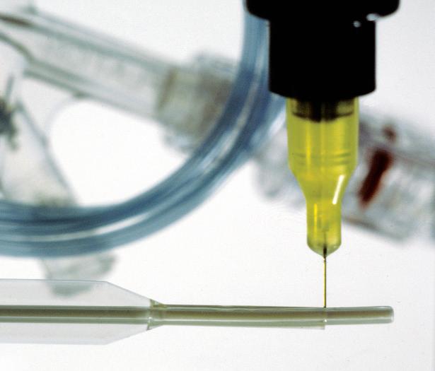
Pot life can act as a guide in figuring out your working life, but some practical experimentation will be useful. Working life is generally shorter than pot life. There are risks in using a material beyond its stated pot life, even if it is still thin enough to apply, because if the cross linking has gone too far, then adhesion and other physical characteristics may be compromised.
Not all manufacturers quote pot life or working life in the same way, so be careful of making data sheet comparisons and use the figures as a guideline. Always test the material in your application and talk to an authoritative supplier. If, for performance reasons, you must use a material with a shorter pot life than ideal for your process, then one likely ramification is increased material wastage from frequent mixing nozzle replacement or auto-purge functions on metering, mixing and dispensing machines.
CURE TIME Cure time can vary from almost “instant” (cyanoacrylate adhesives), seconds (UV curing adhesives) to hours or even days (two part ambient temperature epoxy or single part silicone RTV adhesive sealant). There is a distinction to be made between “handling time” or “fixture time”, and cure time. The former terms refer to the time it takes for the adhesive to cure enough so that the parts can be moved with moderate care - perhaps to a holding area for full cure to occur, or to the next stage of the manufacturing process.
In an ideal world, adhesive cure time would fit in with the production line speed as determined by the takt time. Adhesive specification is about compromises, however, so other selection factors may have trumped the ideal cure time factor. This may mean production bottlenecks, off-line curing, increased WIP, and the resultant required resources (space, time, energy). If assembly jigs or fixtures are required, then longer adhesive handling times invariably mean more jigs, with the associated costs.
If circumstances allow, then fast curing adhesives like cyanoacrylate adhesives or UV light curing adhesives can offer production efficiency. Applications such as bonding surgical instruments and crutches may require a two-part structural adhesive based on epoxy or methacrylate chemistry. In this situation, there is often a balance to be drawn between working life and cure time.
Medical device manufacturers require their processes to be highly efficient and repeatable. However, fast cure time after mixing also implies a short working life, and this may present a number of processing challenges. Higher volumes of continuous production can cope with this, but smaller volumes of inconsistent production will require careful planning in order to reduce material waste. Some of these two-part structural adhesives have cures readily accelerated by heat, although this may need to be done off-line in batch ovens unless volumes allow costly in-line ovens, or for example, by induction heating.
Faster is not always better as it is possible for an adhesive to cure too quickly. For example, if you are working on a very large laminating job, where it takes 10 minutes to apply and spread the adhesive before applying and positioning the laminate, you will need an adhesive with a working life longer than 10 minutes. CONCLUSION Shelf life, working life and cure speed are selection factors to consider when specifying an adhesive for your medical device. It is worth noting that the cost of processing the adhesive is often more than the cost of purchasing the adhesive, so using these features to gain production efficiency will save both time and money, reduce material wastage and enhance productivity while meeting the industry’s regulatory requirements.
WHEN SPECIFYING AN ADHESIVE FOR A MEDICAL ASSEMBLY APPLICATION, SHELF LIFE, WORKING LIFE AND CURE SPEED ARE SELECTION FACTORS TO CONSIDER. A GOOD UNDERSTANDING OF THESE FACTORS CAN HELP MEDICAL DEVICE MANUFACTURERS TO IMPROVE PRODUCTIVITY AND REDUCE WASTE WHEN BONDING, COATING OR MASKING CATHETERS, TUBE SETS, PROSTHETIC JOINTS, BLOOD FILTERS AND MORE.
Realize your vision. Partner with the most innovative team in the industry. Innovative solutions. Engineered to your specific requirements.

MicroLumen.com
BIOCOMPATIBLE EPOXY for bonding, sealing, coating & encapsulation Toughened Adhesive System EP30DPBFMed

• USP Class VI approved • Elongation at break, 75°F 20-40% • Dielectric strength, 75°F 450 volts/mil • Complies with RoHS3 Directive (EU) 2015/863 • USP Class VI approved • Elongation at break, 75°F 20-40% • Dielectric strength, 75°F 450 volts/mil • Complies with RoHS3 Directive (EU) 2015/863
Design
Development
Mould Tooling
Injection Moulding
Beyond the Mould


Your technical experts for Toolmaking and Plastics Injection Moulding
www.pentagonplastics.co.uk websales@pentagonplastics.co.uk Tel: +44 (0) 1403 264 397 |
The GREEN light
MARTIN GADSBY, DIRECTOR AT OPTIMAL INDUSTRIAL TECHNOLOGIES, LOOKS AT HOW PROCESS ANALYTICAL TECHNOLOGY (PAT) CAN SLASH THE ENVIRONMENTAL IMPACT OF MEDICAL PLASTIC MANUFACTURING ACTIVITIES WHILST CREATING VALUABLE OPPORTUNITIES FOR PROCESS IMPROVEMENT.
Growing ecological awareness and stricter environmental regulations are driving positive changes towards greener, more sustainable practices when it comes to manufacturing with plastics. PAT offers a key tool to keep up with these trends and realise even the most ambitious green manufacturing initiatives, especially with plastic which has recently come under scrutiny due to its environmental impact.
PAT can improve the efficiency of raw material production, manufacturing and recycling processes whilst increasing the quality of the final products. This is a system for designing, analysing, and controlling Critical Process Parameters (CPPs) in manufacturing through timely measurements of Critical Quality Attributes (CQAs) defining Quality Target Product Profiles (QTPP).
Ultimately, by using MultiVariate Analysis (MVA) and chemometric models to link CQAs and CPPs, PAT aims to optimise industrial processes by offering an indepth understanding of the manufacturing processes involved. This PAT process knowledge is presented in an easily accessible manner to plant operators via software platforms, such as Optimal’s synTQ knowledge management suite, allowing on-the-fly adjustments of CPPs to meet CQA targets.
The result can be greener manufacturing with lower energy usage, and less waste.
SOLVENT USE Key targets of PAT-led process improvement include reducing energy consumption, waste generation and substandard material production. These goals are some of the main objectives of green chemistry, a movement founded in the 1990s.
In addition to the general resources being used in the manufacturing of medical plastic, there are other resources whose use, and waste treatment can be heavily reduced by PAT-led production, such as hazardous chemicals
PAT offers a key tool for medical plastic manufacturers interested in reducing the environmental impact of their activities.
and solvents. Consequently, by using lower amounts of these chemicals, manufacturing facilities can minimise the environmental impact of their processes.
GREENER PROCESSES PAT acts as the ideal gateway to continuous processing. This is inherently more sustainable than batch manufacturing due to lower energy expenditure. Advanced PAT knowledge management platforms, such as synTQ, also offer ‘digital twin’ functions. These further reduce the volume of resources used, waste generated, and energy consumed, by allowing medical plastic manufacturers to develop, run and test a process data flow before an actual, physical process is started up.
GREENER QUALITY TESTING PATs contribution to developing a cleaner industrial environment does not solely influence the medical plastic manufacturing process, but also encourages the development and implementation of eco-friendly analytical practices in quality control.
The in-line testing procedures at the core of PAT greatly simplify the testing workflow. By doing so, test sample packaging, transport, storage and preservation activities are no longer taking place, as analysis is performed in-line. As a consequence, waste production and energy usage resulting from these tasks are completely eliminated.

A GREEN WAY AHEAD It is clear how medical plastic manufacturers that have not yet implemented a PAT strategy are missing out not only on an opportunity to improve the environmental profile of their production processes and quality testing, but also the associated economic benefits resulting from resource and waste minimisation or avoidance. References 1 Original “manifesto”: Anastas PT, Warner JC. Green Chemistry: Theory and Practice. New York: Oxford University Press; 1998 2 Hosam El-Din Mostafa Saleh and M. Koller (February 28th, 2018). Introductory Chapter: Principles of Green Chemistry, Green Chemistry, Hosam El-Din M. Saleh and Martin Koller, IntechOpen, DOI: 10.5772/intechopen.71191. Available from: https://www.intechopen.com/books/green-chemistry/introductory-chapter-principles-of-green-chemistry
WEBINARS CREATE | ENGAGE | INSPIRE
Our webinars offer an insightful and professional means of connecting you with your target audience through thought leadership and direct interaction.
Our fully managed and hosted webinar service allows you to: • Showcase your expertise and industry knowledge • Raise brand awareness • Transform the way you engage with customers • Run a cost-effective and convenient alternative to conventional seminars • Gain more insights into your target audience • Attain clearly defined and qualified sales leads
To find out more contact Sarah Livingston tel: +44 (0) 1244 952 358 sarah.livingston@rapidnews.com
@MPN_Magazine
One step ahead
Medical device manufacturers are at the forefront of driving industry 4.0, demanding end-to-end control of every aspect of manufacturing visibility and performance and, whether you know it or not, that starts with tooling. For the purposes of this article, tooling is defined as the moulds, dies/jigs and fixtures that facilitate the conversion of raw materials into finished goods. Why is it important? There exists an assumption on the corporate side that as long as the tooling is maintained, it will last indefinitely. However, tool life cycle has come to the surface as a significant factor that directly affects profit and loss, and there is no industry standard, and no quantitative measure for tool life cycle. The corporate executive has visibility into product life cycle. After all, it’s the corporate side where orders are placed and where the finances are managed. Meanwhile, the operations side is charged with managing an open-ended tooling life cycle, with the added complication of trying to find steadily increasing repair funds for ageing tooling that no longer has an asset value. Over a period of time and usage, once the tooling has some “mileage” on it, it’s not hard to imagine that something so critical - yet which is not visible to the stake-holders - can become the catalyst for numerous problems including, but not limited to, tooling asset management, transfer tooling, constant break-downs, spiralling maintenance costs, supply-chain issues, recurring part quality problems etc. The highest specification for mould tooling is class 101, which is guaranteed to last 1M shots/cycles. Many well-maintained tools can last upwards of 10M shots, but once over 1M shots there is a grey area where it is near impossible to predict longevity. How can you bridge the gap between corporate management and manufacturing operations management, and create global visibility of these high value assets? Tooling Pulse, a US-based start-up, has developed a reliable method to quantify tool life cycle, and bridge the gap between corporate management and manufacturing operations by delivering real-time tooling metrics right to the fingertips of all corporate stakeholders.
Founder Paul Mulville explains: “Until now, no-one has been able to accurately define a point in the future that says: “That’s where the tool will fail”, or “that’s when the tool needs to be replaced or phased out”. He added: “We are a real-time global tooling audit and predictive analytics platform that lets you know: What you have, where it is, what condition it’s in and whether it’s sustainable - essentially by quantifying risk using a sophisticated formula of fixed, variable and dynamic inputs to generate tangible outputs that will enable mitigation decisions to be made.” What makes Tooling Pulse different? According to Mulville: “It’s the only product in the space that proactively delivers data (key performance indicators) that allow you to see issues on the horizon, before they become a problem”. In an ideal world we would like to see every area of manufacturing as a module, however, one might argue that tooling is neither a consumable or a tangible and is most often managed by off-site suppliers. Ironically these same off-site suppliers have difficulty communicating the current condition of tooling to non-technical purchasing agents, and the issue becomes almost perpetual. Tooling Pulse aids both the original equipment manufacturer and the supplier with transparent data that allows proactive decisions to be made. In summary, industry 4.0 is as relentless as the tide, and it’s simply unacceptable in 2020 for manufacturing leadership to be driven by failures, fallout, anomalies and breakdowns when predictive analytic technology exists to prevent these issues. Tooling Pulse’s method of capturing data directly from the tool provides the missing link in the chain of manufacturing control and accountability, thereby enabling strategic planning decisions. PAUL MULVILLE, FOUNDER OF TOOLING PULSE, EXPLAINS WHY CAPTURING DATA DIRECTLY FROM THE TOOL ENSURES MEDICAL MANUFACTURERS CAN MAKE PREDICTIVE AND PROACTIVE ACTIONS.
TOM HOOVER, SENIOR MEDICAL BUSINESS DEVELOPMENT MANAGER – AMERICAS, ASSEMBLY TECHNOLOGIES, AT GLOBAL TECHNOLOGY AND MANUFACTURING COMPANY, EMERSON, EXPLAINS HOW ULTRASONIC PLASTIC WELDING IS IMPROVED THROUGH IMPROVED FORCE CONTROL.
The latest advances in ultrasonic welding for medical devices are driven by the need to assemble plastic parts that tend to be smaller and lighter in weight, thinner-walled, and often more contoured than in the past. A growing number of these parts also contain embedded electronics and sensors that require special care in the ultrasonic welding process.
Meeting the medical device industry’s demand for repeatable, strong and consistent welds in these smaller and more delicate components has required the development of improved ultrasonic welding technology. Perhaps the most important recent improvement has been the development of new, more precise methods of force control. This has required a series of changes to the ultrasonic welding actuator and its microprocessor controls.
To achieve the greater and more precise levels of force control required, the developers of Branson ultrasonic welding technology considered not only the capabilities of pneumatic actuators— which remain an industry standard—but also the rapidly advancing capabilities of servo control and technology.
Their solution was a new electromechanical actuation system, recently introduced in Branson GSX welders from Emerson. A key attribute of this new welding platform and its advanced actuation system is substantially more precise and responsive force control through the entire weld process. Downforce is necessary to maintain horn/part contact and ensure the smooth, efficient transmission of ultrasonic energy into the mating parts. Managing downforce more rapidly and precisely has important implications for weld quality.
THE ROLE OF WELD FORCE CONTROL For a given set of weld parameters, variations in force control that result in applying too little force reduce compression of the mating surfaces, reduce the heat generation needed for plastic melt, and result in cold or weaker welds. Similarly, force variations that result in applying too much force can cause part joints or energy directors to deform, deflect or break and may not provide enough time for proper melt flow and polymer entanglement to occur.
Applying just the right amount of force at just the right time results in quality welds with highly consistent characteristics and strength. Ideal force control requires rapid, dynamic changes in the clamp force/downspeed applied by the actuator following the melt of the plastic. This adjustment, called ‘dynamic follow through,’ enables each weld cycle to adapt to part-to-part variances and other factors such as the type of plastic, joint style, and part geometry.
As the speed and precision of force control and dynamic follow-through increase, the strength, quality and consistency of plastic welds follow. For example, the strongest ‘pull force’ for a part weld results from a controlled force profile that allows for complete and random polymer chain entanglement that makes the weld as strong as the parent material (As shown in figure 1).
As seen in the right-most illustration in Figure 1, ideal force control adjusts downforce milliseconds after the melt, allowing polymer chains to extend vertically across the part interface and entangle with each other across the bond line as melt and compression occur before cooling. By contrast, weaker welds, characterised by partial or no polymer chain entanglement, show polymer chains that reassemble parallel to the bond line without entangling across the part interface. The centre weld shows the impact of inadequate force control, while the ‘cold’ weld at left could be caused by too little or too much downforce in too short a weld time.
More consistent and complete polymer chain entanglement and stronger welds are a direct result of technical improvements in force control. By evening out even small force variations very quickly, the process control and actuator in the GSX welder maintain more consistent contact.
RESULTS OF IMPROVED FORCE CONTROL In a series of laboratory tests and and customer trials, the advanced process controls and electromechanical actuator in the GSX-E1 welder reportedly consistently outperformed pneumatically actuated welders, enabling the latest ultrasonic welding platform to:
• Produce welded parts with more consistent and repeatable levels of strength. In a head-to-head comparison of welding performance on identical parts, the GSX-E1 was matched against an excellent pneumatically actuated legacy welder. Results showed that while both welders produced strong welds, the GSX-E1 was able to produce parts with an even higher average pull strength and more consistent and repeatable levels of break force (e.g., lower standard deviation in results), as well as physical characteristics that more closely matched those of parent material.
• Change downforce on a weld within milliseconds as part-to-part melt occurred, resulting in more precise closed loop control over heat generation and dissipation, weld-collapse depth, and weld quality. In another example, a customer evaluated the performance of the GSX-E1 welder when its legacy welder, a pneumatically actuated welder, was unable to change weld downforce quickly enough to avoid bubble formation in the weld zone between two polycarbonate parts. The result was an unacceptable level of scrap parts. The customer found that the more rapid, precise action of the electromechanical actuator and control on the Branson GSX-E1 eliminated the bubbles, producing consistently high-quality welds.
• GSX-E1 repeatability across multiple welders. A customer with a low weld clamp force (~40N) application required a torque test specification on their welded parts maintaining a tight torque value test range of between 0.2Nm and 0.65Nm across multiple welders. Their trial with GSX-E1 welders exceeded the requirement, holding torque values to within a nominal range of approximately 0.2 Nm over a run of
50 production-quality welds—a feat impossible with the customer’s
pneumatically actuated ultrasonic welder.
• Complete challenging part welds with exceptional consistency. The force control capabilities of the GSX-E1 were also proven in applications involving long, delicate, and thin-walled parts. In one application, a customer using a competitive,
servo-actuated ultrasonic welder
struggled to consistently produce welds with high break-push
No entanglement Partial parallel entanglement Complete entanglement Cold Weld Weak Weld Strong Weld
Polymer Chains Bond Line
Figure 1: Polymer chains in cold, weak, and strong welds
strength (>80 lbs) on parts with a very thin (~0.5 mm) plastic shear joint. An extended production trial with the GSX-E1, working at 500 parts per hour, delivered 3,000 parts with an average break force of 152 lbs (nearly double the customer requirement). In addition, the GSX-E1 produced 100% good parts.
In another example, this time involving far-field welds of a long, thin (0.070” wall thickness) tube with a shear joint into a moulded base, a customer was able to produce strong welds with its legacy welder, but sometimes had quality problems including part marking and inconsistent weld depth, resulting in flashing. A weld trial set up in less than fifteen minutes with the new intuitive Branson GSX quickly resolved the problems. Its responsive process control and electromechanical actuator delivered weld amplitude consistently and smoothly, resulting in parts free of markings and flash with higher average pull strength.
The improved force control capabilities built into the new GSX ultrasonic welding platform from Emerson typically enable GSX welders to produce these and similar results while reducing weld cycle time, peak power input, and total weld energy consumption compared to welders with less-responsive and precise actuators.


32 New Product Launches Dynamic Features Technology Pavilions 3 Conference Stages 1-2-1 Meetings Programme Start-Up Zone





MED-TECH INNOVATION EXPO
FURTHER BY SHARING SKILLS HUB UP
Join the fastest growing event in medtech. We’ll see you there!
NEC | BIRMINGHAM | UK FREE TO ATTEND #MedTechExpo @MedTechOnline
PLATINUM PARTNER
UP TO SCRATCH
Whether you are manufacturing parts for use in class III medical devices or class II products, such as syringes or catheters, it is necessary to have a quality management process in place to ensure your products meet industry standards, customer specifications and your own quality benchmarks. be measured for compliance. These criteria need to be considered carefully when planning an efficient quality control procedure. An instant Field of View (FOV) measuring system can be used in cases where 2D measurements are acceptable. In addition, multiple small components can be placed within the FOV and accurately measured within moments - ideal for small medical devices. The use of a telecentric lens will further improve accuracy through the elimination of any distortion in the FOV due to curvature of the lens. STEPHEN SANDERSON, GROUP INSPECTION PRODUCT MANAGER AND GUVEN TUREMEN, GROUP METROLOGY PRODUCT MANAGER, BOTH FROM MANUFACTURER VISION ENGINEERING, DISCUSSES HOW MANUFACTURERS CAN ENSURE THE QUALITY OF PLASTIC COMPONENTS.
A quality control process must be reliable and easily documentable to provide proof of compliance. The detail of the quality management system will be dictated by the customer’s product specification which, in turn, will guide the choice of inspection and measurement systems used within the quality infrastructure.
VISUAL INSPECTION Visual inspection checks are undertaken to ensure parts meet specific requirements in terms of colour and surface finish. It also makes sure that there are no residual material fragments left over from the manufacturing process.
In many instances, due to the size of the components, a microscope will be required to conduct the inspection.
Visual inspection checks alone are not always sufficient to assess product compliance. In instances where there are tight-tolerance standards, a series of measurements may be included in the quality management process.
MEASURING COMPONENTS There are varying degrees of accuracy when it comes to measuring components, from basic comparison against a reticule to measuring distance in terms of micrometres. The need to measure a variety of components can make the process more complicated. To maintain accuracy and efficiency a variety of measurement types may need to be incorporated into the quality protocol. The solution may be to combine an optical measurement system with a video measuring system. Video measurement offers speed of measurement, making it ideal for components where edges are clearly visible.
Where parts are more complex or have difficult to view features, the intricacies are better seen with the aid of an optical system. This is particularly useful in cases where the plastic is black or transparent. This ability to switch seamlessly from a video to an optical view maintains accuracy whilst offering time saving benefits.
Measurement procedures for complex parts may also require measurements in three axes or measurement of 3D forms, where a mixture of non-contact and contact (touch-probe) measurement methods can be combined.
With such a system, features that can be displayed clearly via the digital camera are measured using the non-contact method and others with poor edge definition or concealed features can be measured with a touch-probe.
Switching between probe and non-contact measurement will reduce measurement time, maintaining accuracy without compromising speed of checks. Inclusion of a motorised zoom lens further optimises the process offering the ability to incorporate magnification changes into the assessment process.
SELECTING THE APPROPRIATE EQUIPMENT A successful quality control process is reliant on utilising the appropriate equipment to ensure not only accuracy but efficiency. The simplest way to select the best system for your business is to share your requirements with the experts. They will then be able to advise you, and tailor the inspection and measurement system in order to deliver the ideal solution for you.
When creating the protocol for a quality management system, the degree of accuracy will need to be taken into consideration.
Quality managers will also need to review the measurement range which will dictate whether a two or three axis measurement system should be used.
High value, safety critical devices will often be made up on a number of components, all of which will need to


