25 minute read
..................................................... 49 © Mark Barnes | Vice President, Des-Case

GESTION LUBRICACIÓN

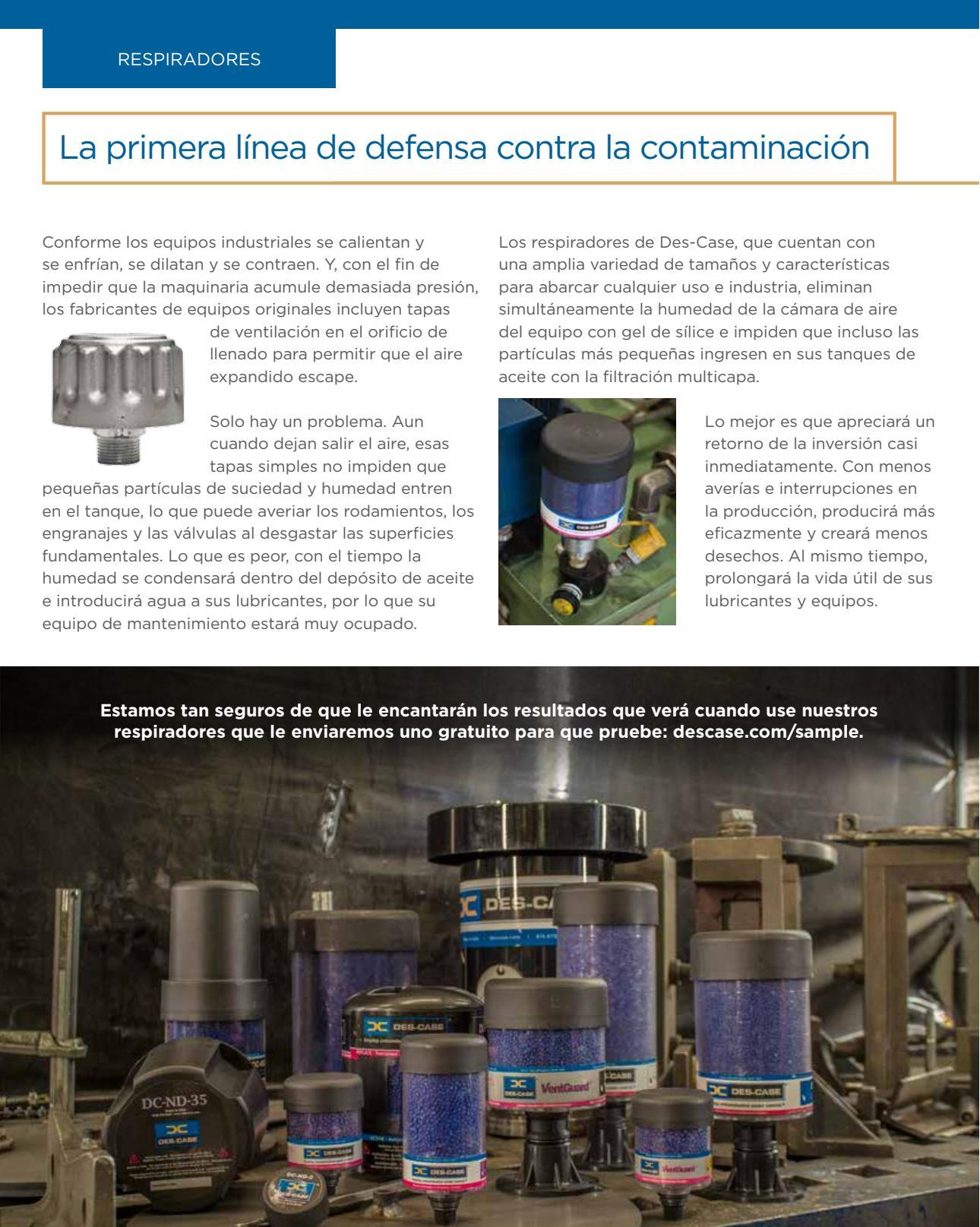
Advertisement

© Mark Barnes | Vice President, Des-Case
I. INTRODUCTION
THE IMPORTANCE OF LUBRICATION TO PUMP RELIABILITY
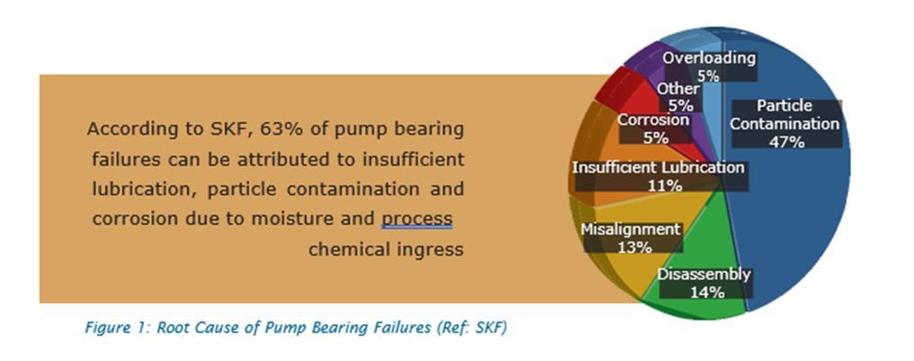
According to SKF, a leading bearing and seals manufacturing company, there are many different causes of pump bearing failure (Figure 1). But a closer look at the data will reveal a much simpler picture. Looking at just three categories; particle contamination, corrosion, and insufficient lubrication, it’s clear that issues related to the correct application, health, and cleanliness of the lubricant account for as much as 63% of all pump bearings failures, making lubrication arguably the most important aspect of maintaining centrifugal pumps.
3 Fuente: Mark Barnes – VP Des-Case - https://www.cbmconnect.com/maximizing-pump-reliability-through-precisionlubrication/ 49
BEARING TYPES AND LUBRICATION
Most small ANSI pumps come equipped with single row deep groove ball radial bearings and either paired or double row ball angular contact thrust bearings. The bearings are lubricated by means of a wet-sump or slinger ring. For very small ANSI pumps it’s not uncommon to use grease and while grease offers some advantages, particularly with leakage control and stop-start applications, oil lubrication is generally preferred in order to control heat and contamination within the lubricant, particularly as pump size increases.
For API pumps, radial and thrust bearing selection varies based on energy density (Power x Rated Speed). For lower energy densities, radial bearings are typically double row deep groove ball bearings, while the thrust bearings are often angular contact ball bearings. However, for larger pumps with higher energy densities, cylindrical roller or even sleeve bearings are used for radial support while thrust bearings are commonly paired with tapered roller bearings or tilting pad bearings. Just like ANSI pumps, API pump bearing lubrication is commonly via wet-sump where tilting pad bearings are used. It’s recommended to employ a small external circulating lubrication system, either via a shaft driven pump or separate lube oil pump.
LUBRICANT TYPE AND SELECTION
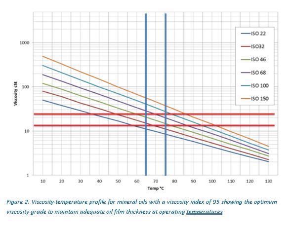
Most oils used in centrifugal pumps are either rust and oxidation inhibited (R&O) mineral oils or antiwear mineral oils (AW). R&O oils are formulated with approximately 95-97% by volume of base oil with the balance being a careful blend of antifoam, antioxidants, corrosion inhibitors, and demulsibility agents. In some cases, either for consolidation purposes or where thrust loading is expected, antiwear additized (AW) oils are recommended. While both work effectively, AW additives can sometimes impair the oil’s ability to shed moisture if the lubricant becomes contaminated with water. When selecting the correct oil for a pump, the most important factor is the oil’s viscosity at operating temperature. For rolling element bearings used in pumps, the minimum viscosity recommend is typically around 13 cSt (1). However, for optimum reliability it is generally recognized that having a viscosity that is 1.5-2.0 that of the minimum (Kappa=1.5-2.0) is preferred. Using the chart shown in Figure 2 which illustrates the viscosity temperature profiles for conventional minerals oils with a viscosity index (VI) of 95, the recommended lubricant for a pump operating between 65-75 C (150-165 F) would be an ISO VG 46, while for operating temperatures from 75- 82 C (165-180F) an 50
ISO VG 68 should be used. For oil temperatures above this, either ISO VG 100 mineral oil or preferably PAO synthetic oil should be used. Where grease lubrication is preferred, the grease selected should have a base oil viscosity at operating temperatures that is 2.0-2.5 times the minimum (Kappa=2.0-2.5). Typically an NLGI grade 2 grease should be used with a thickener that has a low oil bleed rate and high resistance to changes in consistency due to mechanical shear. In practical terms, it is often possible to use the same grease used for electric motor lubrication in smaller direct coupled process pumps since most electric motor greases have a base oil viscosity grade around 100-120 cSt at 40 C, resulting in Kappa values of 2.0-3.0 for typical pump operating temperatures.
MAINTAINING CORRECT OIL LEVEL
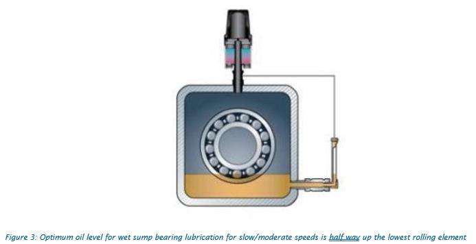
For pumps, oil level is critical. For wet sump rolling element bearing applications operating at moderate speeds (<1800 RPM), the optimum oil level is half way up the bottom element of the bearing (Figure 3). Too low and the risk of lubricant starvation is high; too high and increased viscous drag can cause bearing temperatures to rise and increase energy consumption. For small ANSI pumps this can be a very real challenge, since smaller bearing dimensions can mean trying to maintain oil level to ±1/4”.
51
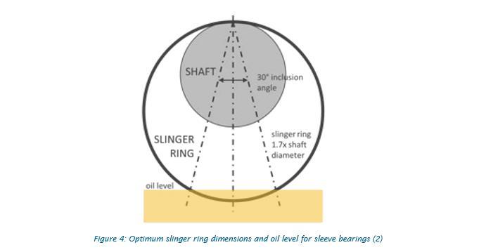
For higher speeds, lower oil levels should be maintained to avoid excessive viscous drag and subsequent increases in oil temperature (2). Under these conditions, a slinger ring, flinger disc, or other means of force feeding oil to the bearings should be used. For sleeve bearings, oil rings must be used unless a force fed lubrication system is deployed. The optimum dimensions of the slinger should be 1.7x the shaft diameter with the oil level maintained to ensure a 30° inclusion angle for the oil, as shown in Figure 4 (2). It has been shown that the oil’s viscosity and immersion depth has a profound impact on slinger ring rotation and stability as does the horizontality of the shaft. Because of this, some pump manufacturers have replaced conventional metallic slinger rings with non-metallic slingers (3), while the use of flinger discs that cannot migrate are also recommended (2).
52

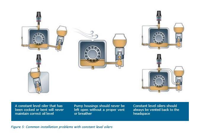
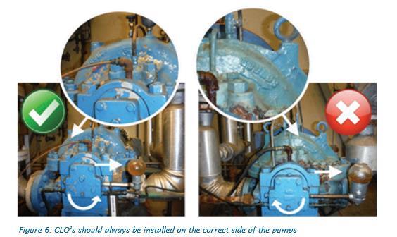
Because of the importance of maintaining oil level, it is not uncommon to use a constant level oiler (CLO) on pump housings. While these can be effective, a few simple precautions should be observed. When the CLO is first installed, the level should be set carefully (remember, ±1/4” can make a big difference). When installing a CLO, it should never be cocked or bent out of position as shown in Figure 5. It is also important that a proper breather is used and that the CLO is vented back to the headspace. Because of the Bernoulli Effect (the same effect as the “pull” a high speed train has when passing by a station platform), having an open vent can cause oil levels to fluctuate with changing ambient conditions. In fact, in one paper mill it was reported that whenever an outside door was opened, the oil level in all the CLO’s dropped by 1/2″ due to changes in air flow patterns! Another common mistake with CLOs is installing them on the wrong side. It is not uncommon to walk down a row of pumps and find two pumps side-by-side, one pump having the CLO installed on the correct side while the pump right next to it has the CLO installed incorrectly. This is particularly important in higher speed pumps where the oil level is higher on one side than the other due to the “wake” created by the bearing rotating in the oil. The result can be a significant increase in oil temperature and can impact the effectiveness of the slinger ring as viscous drag causes the ring to rotate slower, potentially starving the bearing of oil. The easiest way to determine the correct side to install a CLO is to stand looking along the shaft and picture an arrow in the oil sump with the head of the arrow pointing in the direction of shaft rotation. With the imaginary arrow in mind, the head of the arrow not only depicts the direction of shaft rotation but also the correct side to install the CLO (Figure 6).
53
In order to ensure correct oil level, a visual level gauge should always be installed. The presence of oil in the oil bulb of a CLO should never be taken as an indicator that the pump is full. Any blockage in the line connecting the CLO to the oil sump can prevent oil from flowing into the bearing housing, while sunlight and time can cause the bulb of the LO to stain such that the “bathtub ring” left behind might make it appear 54that sufficient oil is present when in actualityit could be completely empty. Care should also be taken when
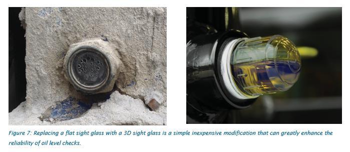
filling a CLO. If the bulb is filled beyond 60-70% full, there may be insufficient headspace within the CLO to permit oil to flow into the bearing housing. To ensure correct oil level, many pump housings are equipped with a sight glass. But while these are effective when new, over time the glass can become stained making it very difficult to ascertain if the correct level of oil is in place, particularly in low-light areas. A simple solution tothis problem is to replace the flat sight glass with a 3D sight glass as shown in Figure 7. A 3D sight glass offers viewing from any angle making visual level checks easier and more accurate.
CONTAMINATION CONTROL
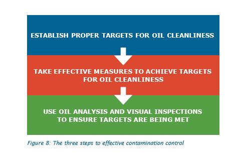
With the single largest contributing factors to pump bearing reliability being contamination (Figure 1), it stands to reason that this should be a major focus for any reliability centered lubrication program. Major sources of contamination related failures include 3-body abrasion, particle induced fatigue, and corrosion. For the purposes of this paper, we’ll limit it to the two most common – particles and moisture – though in some settings and applications, the impact of contamination with process fluids cannot be overlooked. Contamination control can be achieved through a three-step process (Figure 8).
55
STEP 1: ESTABLISH PROPER TARGETS FOR OIL CLEANLINESS
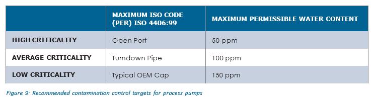
Targets need to be set such that the probability of a contamination induced failure is minimized. In doing so, we need to look at the consequence of failure on three fronts; the potential financial impact of a failure (both in terms of lost production and repairs costs), any safety hazard that would occur in the event of an expected failure, and any potential for a spill or other environmental non-compliance that might result from a failure. The input from these three areas should, to a large extent, drive how clean (or dirty) you can or should run the pump. While it is almost impossible to provide a definitive set of targets for every user, Figure 9 provides some reasonable and pragmatic targets for process pumps based on criticality. These limits should be set as warning limits for routine oil analysis, with condemning limits set at a 100% increase in water (i.e. an increase from 100 ppm to 200 ppm of moisture for average criticality pumps) and an increase of two ISO codes (i.e. from 15/13/10 to 17/15/12 for critical pumps). The goal should be to maintain the oil’s cleanliness at all stages of the fluid’s life: from storage and handling, during introduction into the pump, and finally while the oil is in service until it’s time for an oil change.
56
STEP 2: TAKE EFFECTIVE MEASURES TO ACHIEVE TARGETS FOR OIL CLEANLINESS
Controlling contaminants requires a two-step process: exclusion followed by removal. These will be discussed below:
Contamination Exclusions
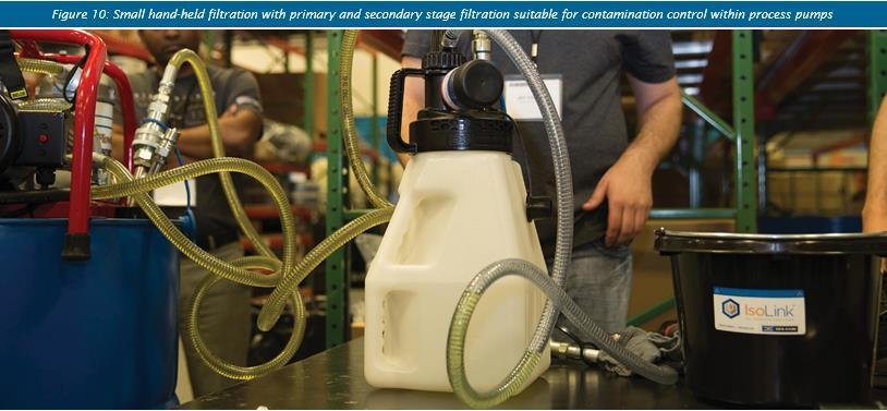
Simply stated, it is far better to prevent contaminants from getting into the pump in the first place than to try to remove them after the fact. This is particularly true since most experts recognize that the cost to exclude contaminants is about one tenth the cost to remove it once inside the oil sump. Contamination exclusions require a holistic focus on fluid management from how the oil is stored and dispensed, to how it is introduced into the pump, and how that oil is kept clean during normal operations. Without exception, all new oils should be pre-filtered prior to introducing them to any critical pump. The goal should be to ensure that the oil within the pump housing is maintained at or below the target cleanliness levels indicted in Figure 9. In order to achieve this, it is likely that most new oils will need to be filtered to 1-2 ISO codes lower than the targets indicated in Figure 9 using a filter with a beta rating at 3 microns of at least 200 or better. Even at this level of filtration, it is advisable to pass the oil through the filter a minimum of 3-5 passes to achieve the targeted fluid cleanliness levels. Depending on the amount of water present in new oils, it may also be necessary to use a water removal element in series with a fine particulate filter. One of the major sources of contamination ingress is when the oil is being transferred from the oil container into the pump. Since by definition this is occurring out in the plant, opening the oil transfer container or pump to the ambient operating environment may be sufficient to cause oil cleanliness levels to exceed our target. Instead, oil should be transferred in a sealed container, preferably one that is protected with a breather, and has quick connects that mate to quick connects installed on the pump (Figure 10). This ensures that oil that is being transferred never “sees” the operating environment.
57
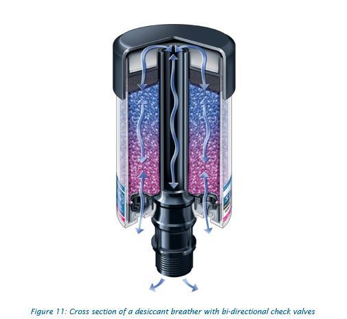
Once the oil is in the oil sump, it must be protected from contamination ingress. The best and most effective way to do this is to use a desiccant breather. During normal operations, pumps will breathe causing dirty, and often moist, plant air to enter the bearing housing. Using a desiccant breather that contains a 3 micron particle filter media in conjunction with a silica gel desiccant to remove moisture helps ensure that any air that enters the pump through the vent/breather port is both clean and dry. For most pump applications, the most effective type of desiccant breather is a vented breather. This type of breather has two sets of bidirectional check valves controlling air flow into and out of the breather (Figure 11).
With this arrangement, if the pump is at steady state (constant temperature and balanced pressure or shutdown) the check valves isolate the breather and by inference the pump from the ambient environment. Not only does this offer better contamination control but it will also helps extend the life of the breather. When using a CLO, it’s important that the CLO be vented back to the pump housing headspace to avoid any possibility of pressurization caused by the use of a vented breather. In conjunction with proper breathers, seals are also important. For the most part, pump manufacturers and reliability focused users are moving away from simple lip seals to bearing isolators, including labyrinth style seals and magnetic face seals. Properly selected and installed, these types of seals have proven to be very effective at isolating the oil sump from the air around the shaft seal interface. However, experience has shown that despite their effectiveness, a desiccant breather (as opposed to completely sealing the vent port with a pipe plug) should always be used in conjunction with proper seals since humidity will find a way into the oil sump. By sealing the sump with bearing isolators and plugging the vent port, moisture that enters the sump will remain sealed inside the headspace, causing the oil to become saturated with moisture. Since the silica gel inside a desiccant breather is in contact with the headspace, the air inside the pump housing will be dry, which as a result of Henry’s law will ensure that the oil also remains dry (4). 58
Contamination Removal
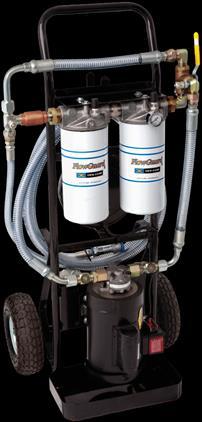
Even with the best seals and breathers installed, there is often a need to employ periodic offline filtration to maintain and achieve the desired target cleanliness and dryness levels. The easiest way to do this is to use a small portable filtration unit (Figure 12). The preferred configuration is dual stage filtration, with a coarse particle or water removal element in the first stage and a fine filter with a beta 200 rating at 3 microns as the second stage of filtration. In order to effectively deploy portable filtration, each pump should be adapted to include quick connects so the filtration system can be easily connected and disconnected without exposing the oil to the ambient environment. If multiple grades or types of lubricants are in use, a different filtration system should be used. Flow rates should be selected so that the effective rate of flow through the filter cart does not exceed 5% of the total volume (i.e. no more than 1 GPM flow rate for a 10 gallon sump) to prevent the possibility of foaming. For smaller pumps, an effective way to achieve this is with an air driven rotary pump, where air flow to the air motor can be regulated to lower flow rates to comply with the 5% flow rate restriction. For very small pumps, it may not be possible to lower flow rates enough requiring that offline filtration be done while the pump is shut down. In order to effectively decontaminate the sump, the oil should be filtered with sufficient time for the total volume of oil within the pump to be passed through the filter cart a minimum of 5-7 times. Oil analysis (step 3) can be used to validate that the selected filter combination and total time for filtration is sufficient to meet the desired target cleanliness and dryness targets.

STEP 3: USE OIL ANALYSIS AND VISUAL INSPECTIONS TO ENSURE TARGETS ARE BEING MET
For critical pumps, the value of predictive maintenance (PdM) cannot be overstated. Particularly for production critical assets, knowing that a pump is starting to fail months in advanced allows for appropriate planning for corrective action to be taken. When starting a pump PdM program, most reliability focused companies start with vibration analysis and often with great success. The reasons for this are quite straightforward; With high speeds and fairly simple mechanical design, even the most basic 59
vibration analysis program can effectively diagnose impending bearing failure as well as a number of other potential failure modes. Unfortunately, few companies choose to perform oil analysis on pumps. While there are several contributing factors such as cost and the ability to obtain a representative sample, perhaps one of the primary reasons is sump size. Since most ANSI and smaller API pumps only use a few gallons or less of oil, the conventional wisdom is often, “we could change the oil for the same cost as an oil sample; why bother?” Under the assumption that the primary purpose of oil analysis is to time oil changes, this philosophy makes total sense. Why would you spend $20 sampling and analyzing the oil when the oil can be changed for only $15? However, this is missing the purpose of oil analysis. Oil analysis is about validating the health of the system as a whole. As stated earlier, one of the main causes of premature bearing failure is contamination with particles or moisture. And while vibration analysis will provide an indication once the bearing starts to fail, oil analysis can proactively warn of the potential for a contamination induced failure through careful monitoring of particle and moisture contamination within the oil. Likewise, other failure modes such as the correct oil or slinger ring wear are far better identified using oil analysis. Figure 13 provides a summary of the more common failure modes and which technology is best suited as a primary and secondary detection method.

60
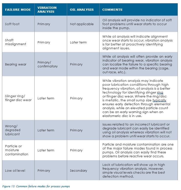
The take home from Figure 13 is that both vibration analysis and oil analysis are necessary to successfully identify problems, with studies indicating that problems show up first in either vibration analysis or oil analysis in almost equal proportions (5).
61
In addition to vibration and oil analysis, preforming a basic daily or weekly visual inspection of pumps is an easy and effective way to identify emergent issues. For pumps with slinger rings, it’s common to have a sight glass through which the ring can be observed “lifting oil”. These should be checked for normal operation. Likewise, oil level should be checked using a 3D sight glass or oil level indicator. Also, remember to not trust the constant level oiler as an indicator that the pump is full of oil. If a constant level oiler is in use, it should be checked and refilled as necessary, noting any sudden change in oil level/usage. The color of the oil in the bulb should also be observed.
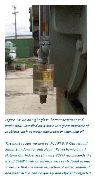
While it’s not uncommon for oil color to change slowly over time due to the photocatalytic effect of sunlight, a sudden darkening or change in color may indicate an issue that requires closer inspection. The desiccant breather should also be checked. While the breather is designed to change color as the silica gel becomes saturated, a sudden change can indicate a more serious problem. It’s also good practice to observe the direction in which the color changes. A color change from the bottom up is simply the breather doing its job by removing moisture as air is pulled into the pump, while a color change in the opposite direction (top down) indicates that moisture has entered the oil sump through a seal or other source. Finally, one simple yet effective tool to help diagnose lubrication problems is to install an oil sight glass, commonly referred to as a bottom sediment and water (BS&W) bowl. These simple devices installed on the drain port can warn of issue such as excessive wear (shiny particle appearing in the bottom of the bowl), water (free or emulsified water) or a color change indicating oil degradation (Figure 14).
STANDBY VS DUTY PUMPS
In some industries such as petrochemical and refining, it is common practice to have two pumps for each critical application, often referred to as the standby and duty pumps. While having redundancy for specific applications may seem like an excellent way to ensure process reliability, it also creates some maintenance challenges. Specific to lubrication is the impact of the stop/ start cycle on the ability of the oil to lubricate. First, when a pump is first started up, the oil in the sump will likely be at a lower temperature and hence have a higher viscosity. As stated earlier, the effectiveness of slinger rings, and to a lesser extent flinger discs, is influenced by the oil’s viscosity, so some degree of dry start is likely. Second, is the impact of contaminants; both particles and moisture. Whenever a pump is shut down, the oil will cool as will the headspace above the oil. As this occurs, the pump will need to draw in air from the outside to compensate for the change in internal pressure with temperature. In doing so, it is important that any particles and moisture are removed from the ambient air before it enters the pump housing, making it even more important to protect stop/start equipment with desiccant breathers. Where this does not occur, it is not 62uncommon to see fretting corrosion
on bearing raceways when equipment has been shut down for extended periods of time. While standby pumps and redundant assets may appear to need less of a focus on precision lubrication, it could be argued that the opposite is true.
CONCLUSIONS
For any plant that relies on centrifugal pumps for critical production process, there should be no greater focus than on pump reliability. Though simple in design, there are many aspects to effective lubrication of pumps, which if followed, will help ensure a long and sustainable life in even the most severe applications.
REFERENCES
1. SKF MRC Bearing Solutions for Pumps Catalog 2. Heinz Bloch “Centrifugal Pump Cooling and Lubrication Application”, Proceedings of the 22nd
International Pump Users Symposium, Turbomachinery Laboratory, Texas A&M University, College
Station, Texas 2005. 3. Simon Bradshaw “Understanding the Causes of Black Oil”, Proceedings of the 17th International
Pump Users Symposium, Turbomachinery Laboratory, Texas A&M University, College Station,
Texas, 4. Mark Barnes “Mixing Oil and Water Part 2: Strategies for Removing Water” Uptime Magazine,
April/May 2011, 5. Bryan Johnson “Oil Analysis Success at a Power Generation Station” Practicing Oil Analysis
Magazine, July-August
REFERENCIAS LO MEJOR DE LA WEB:
https://www.cbmconnect.com/maximizing-pump-reliability-through-precision-lubrication/
THE AUTHOR: MARK BARNES VICE PRESIDENT, DES-CASE
Mark Barnes serves as Vice President of the Des-Case Reliability Services team. In this role, Mark and his team of lubrication experts help educate end-users on the value of precision lubrication to asset reliability and provide support to help asset intensive company’s change the way they perform lubrication.
63
¡LO LOGRAMOS GRACIAS A TI! Todo es posible…
El Equipo de LubricarOnLine, RDL Lubricación y Mantenimiento Industrial, LubricarOnLine Centro de Excelencia, gracias totales por aprender con nosotros en este 2021 ... A los más de 300 estudiantes capacitados por nuestros 15 programas desarrollados durante este año, 5000 lectores de nuestra RDL, 5 socios mundiales en 6 países este año, gracias por elegir continuar su educación con nosotros (ya sea a través de la pantalla de su computadora con aprendizaje a distancia, clases en vivo, en sus instalaciones). Presentamos nuestro Website de la RDL LMI, nuestra plataforma de entrenamiento se actualizo para mejorar la experiencia de los participantes con el objetivo de Generar Habilidades y Competencias.
64
TOMADO DE: https://www.descase.com/resources/what-is-a-breather/
65
ENTRENAMIENTOS Y SEMINARIOS VIRTUALES INTERNACIONALES: TRIBOLOGÍA Y LUBRICACIÓN, GESTIÓN DE MANTENIMIENTO, GESTIÓN ACTIVOS, GESTIÓN DE LA SEGURIDAD DE PROCESOS. Felicitaciones a todos los participantes Gestión de la Lubricación, Gestión de Seguridad de Procesos, Gestión de Paradas de Planta de Mantenimiento de Colombia, Ecuador, Perú, Chile, México. ¡¡¡Muchas gracias a todos los participantes!!!

66

¡Contáctanos!
https://bit.ly/ComercialTecnicana
67

68
Reciban un cordial saludo de parte del equipo de trabajo, de la primera revista digital iberoamericana especializada en Lubricación, Confiabilidad e Integridad Activos y Seguridad de Procesos Industriales. Próxima Edición Febrero 15 del 2022.
Es una publicación abierta y por invitación, con una misión clara: Construir el Conocimiento desde una sólida base de creatividad, innovación, investigación y desarrollo, integrando las Nuevas Tecnologías de la Información al servicio de la comunidad iberoamericana de estudiantes y profesionales involucrados en las áreas de Lubricación, Mantenimiento, Confiabilidad e Integridad, Gestión de Activos, Dirección de Proyectos, Gestión de la Seguridad de Procesos. ¿Eres Gerente o Director de Mantenimiento, Analista de Integridad Mecánica, Ingeniero de Confiabilidad, Director Proyectos, Asset Manager?; nos encantará tenerle entre nuestros autores. https://revistalubricaronline.org/envie-su-articulo-aqui/, https://www.lubricaronline.com/.
Instrucciones a los autores y condiciones de publicación de los trabajos originales e inéditos
Formato: archivo de Word
Fuente: Arial 10
Interlineado: sencillo
Máximo de cuartillas (hojas): 10
Las ilustraciones y gráficos deben ser en formato JPG y resolución mínima de 500 x 500px. Si son de otro autor, colocar los créditos
Colocar las direcciones de correo electrónico, empresa, cargo y país de origen del autor
Las citas bibliográficas en cursiva y citar al autor de estas al final del texto
Colocar la bibliografía y/o cibergrafía consultada
Síntesis curricular del autor, no mayor de cuatro líneas.
Nuestra Junta Editorial se reserva el derecho de publicación, luego de una revisión exhaustiva de los trabajos enviados. RDL Lubricación y Mantenimiento Industrial ® no se hace responsable de las opiniones emitidas por los articulistas.
69
Los usuarios pueden presentar sus trabajos, con las ventajas que les ofrece la Revista:
Los autores conservan los derechos de autor y la posibilidad de publicar en otros medios, siempre y cuando se reconozca a RDL Lubricación y Mantenimiento Industrial ® como el primer medio en el cual fue publicado. Difusión a más de 5000 suscriptores directos alrededor del mundo, especialmente en Iberoamérica.
CONFIRMEMOS SU PARTICIPACIÓN Nain Aguado Q. I.M, Esp., MBA Dirección Proyectos Director General RDL L&MI https://revistalubricaronline.org/ https://www.lubricaronline.com/index.php https://lubricaronlinecentrodeexcelencia.sabionet.com/
70