Hydrogen Storage Technologies
Edited by Mehmet Sankir and Nurdan Demirci Sankir
This edition first published 2018 by John Wiley & Sons, Inc., 111 River Street, Hoboken, NJ 07030, USA and Scrivener Publishing LLC, 100 Cummings Center, Suite 541J, Beverly, MA 01915, USA © 2018 Scrivener Publishing LLC
For more information about Scrivener publications please visit www.scrivenerpublishing.com.
All rights reserved. No part of this publication may be reproduced, stored in a retrieval system, or transmitted, in any form or by any means, electronic, mechanical, photocopying, recording, or otherwise, except as permitted by law. Advice on how to obtain permission to reuse material from this title is available at http://www.wiley.com/go/permissions.
Wiley Global Headquarters
111 River Street, Hoboken, NJ 07030, USA
For details of our global editorial offices, customer services, and more information about Wiley products visit us at www.wiley.com.
Limit of Liability/Disclaimer of Warranty
While the publisher and authors have used their best efforts in preparing this work, they make no representations or warranties with respect to the accuracy or completeness of the contents of this work and specifically disclaim all warranties, including without limitation any implied warranties of merchantability or fitness for a particular purpose. No warranty may be created or extended by sales representatives, written sales materials, or promotional statements for this work. The fact that an organization, website, or product is referred to in this work as a citation and/or potential source of further information does not mean that the publisher and authors endorse the information or services the organization, website, or product may provide or recommendations it may make. This work is sold with the understanding that the publisher is not engaged in rendering professional services. The advice and strategies contained herein may not be suitable for your situation. You should consult with a specialist where appropriate. Neither the publisher nor authors shall be liable for any loss of profit or any other commercial damages, including but not limited to special, incidental, consequential, or other damages. Further, readers should be aware that websites listed in this work may have changed or disappeared between when this work was written and when it is read.
Library of Congress Cataloging-in-Publication Data
ISBN 978-1-119-45988-0
Cover image: Mehmet Sankir and Russell Richardson
Cover design by Russell Richardson
Set in size of 11pt and Minion Pro by Exeter Premedia Services Private Ltd., Chennai, India
in the USA
987654321
Łukasz Gondek, Joanna Czub, Alicja Klimkowicz, Antoni Żywczak and Konrad Świerczek
4.2 Production of Ti/Zr-Based Amorphous and Quasicrystals Alloys
4.3 Hydrogen Storage in T-Zr-Based Amorphous Alloys
4.3.1 Gaseous Hydrogenation
4.3.2 Electrochemical Hydrogenation
4.4 Hydrogen Storage in the Ti/Zr-Based Quasicrystal Alloys 130
4.4.1 Gaseous Hydrogenation
4.4.2 Electrochemical Hydrogenation
4.5 Comparison of Amorphous and Quasicrystal Phases on the Hydrogen Properties
4.6 Conclusions
5 Electrochemical Method of Hydrogenation/Dehydrogenation of Metal Hydrides
N.E. Galushkin, N.N. Yazvinskaya and D.N. Galushkin
5.1 Introduction 148
5.2 Electrochemical Method of Hydrogenation of Metal Hydrides 151
5.2.1 Hydrogen Accumulation in Electrodes of Cadmium-Nickel Batteries Based on Electrochemical Method 151
5.2.2 Hydrogen Accumulation in Sintered Nickel Matrix of Oxide-Nickel Electrode 155
5.2.2.1 Active Substance of Oxide-Nickel Electrodes 155
5.2.2.2 Sintered Nickel Matrices of Oxide-Nickel Electrodes 157
5.3 Electrochemical Method of Dehydrogenation of Metal Hydrides 161
5.3.1 Introduction 161
5.3.2 Thermal Runaway as the New Method of Hydrogen Desorption from Hydrides 164
5.3.2.1 Thermo-Chemical Method of Hydrogen Desorption 164
5.3.2.2 Thermal Runaway: A New Method of Hydrogen Desorption from Metal Hydrides 164
5.4 Discussion 166
5.5 Conclusions 172 References 173
6 Activated Carbon for Hydrogen Storage Obtained from Agro-Industrial Waste
Yesid Murillo-Acevedo, Paola Rodríguez-Estupiñán, Liliana Giraldo Gutiérrez and Juan Carlos Moreno-Piraján
6.1 Introduction
6.2 Experimental
6.3
6.4
7
R. Pedicini, I. Gatto, M. F. Gatto and E. Passalacqua
7.1
7.3
7.2.3
7.2.4 Graphene
7.2.5 Carbon Nanotubes (CNTs) and Carbon Multi-Walled Nanotubes (MWCNTs)
7.3.1 Polyaniline (PANI), Polypyrrole (PPy) and Polythiophene (PTh)
7.3.2 Hyperbranched Polyurea (P-Urea) and Poly(Amide-Amine) (PAMAM)
7.3.3 Microporous Polymers (PIMs)
7.3.4 Conjugated Microporous Polymers (CMPs) 208
7.3.5 Hyper-Cross-Linked Polymers (HCPs)
7.3.6 Porous Aromatic Frameworks (PAFs)
7.4 Composite Materials Made by Polymeric Matrix
7.4.1 Composite Poly(Amide-Amine) (PAMAM)
7.4.2 Polymer-Dispersed Metal Hydrides (PDMHs)
7.4.3 Mn Oxide Anchored to a Polymeric Matrix
7.5 Waste and Natural Materials
7.6 Conclusions
8
8.2.1.2
8.2.1.3
8.2.1.4
8.3 Beneficial Effect of Graphene: Key Results with Light Metal Hydrides (e.g., LiBH4, NaAlH4, MgH2)
8.3.1 Borohydrides (Tetrahydroborate) as HS Material
8.3.1.1
8.4
8.5
8.5.1 Catalytic Effect of Graphene on Sorption Behavior of Mg/MgH2
8.5.2 Nanoparticles Templated Graphene as an Additive for MgH2
9.2.1
Preface
Our heavy dependence on fossil fuel resources, which is the cause of worldwide problems, has to be reduced in order to improve the environment and, in turn, the impact it has on human health. Hydrogen has drawn great attention as a nonpolluting energy carrier due to its diverse methods of production and storage. In the first volume of our series, Advances in Hydrogen Production and Storage, we thoroughly introduced hydrogen production technologies. However, since hydrogen storage is considered a key technology for stationary and portable power generation, especially for transportation, the second volume of the series is devoted to hydrogen storage technologies. This volume covers the novel technologies used to efficiently store and distribute hydrogen. Discussed are the underlying basics, as well as advanced details, of hydrogen storage technologies, which is highly beneficial for science and engineering students as well as experienced engineers and researchers. Additionally, the book was written to provide a comprehensive approach to the area of hydrogen storage for readers from a wide variety of backgrounds. The intent of the book is to satisfy the need for a broad coverage of the hydrogen storage technologies. Therefore, it was written by distinguished authors with knowledge and expertise in areas of hydrogen storage, whose contributions can benefit readers from universities and industries. The editors wish to thank the authors for their efforts in writing their chapters.
We have separated the book into two major parts: Chemical and Electrochemical Hydrogen Storage and Carbon-Based Materials for Hydrogen Storage. In Part I, hydrogen storage technologies within the context of chemical and electrochemical methods are clearly discussed in five chapters. Chapter 1 focuses on a multistage compression system based on metal hydrides for hydrogen storage. It also includes the development of a validated numerical analysis of a three-stage compression system. Chapter 2 discusses metal-N-H systems and their physicochemical properties for hydrogen storage. Mg-based nanomaterials with enhanced sorption kinetics for hydrogen storage are thoroughly introduced in Chapter 3. Next, in Chapter 4, evaluation of gaseous and electrochemical hydrogen
Preface
storage performances of Ti-Zr-Ni alloys are analyzed. The final chapter of Part I, Chapter 5, deals with the electrochemical methods for hydrogenation/dehydrogenation of metal hydrides. The five chapters in Part II are devoted to carbon-based materials for hydrogen storage. Chapter 6 covers the activated carbon obtained from agro-industrial waste for use in hydrogen storage. Chapter 7 introduces the concept of hydrogen storage with carbonaceous materials. Next, Chapter 8 provides a fairly comprehensive introduction to hydrogen storage characteristics of graphene addition in hydrogen storage materials. Part II concludes with a discussion in Chapter 9 of the crucial features of hydrogen adsorption of nanotextured carbonbased materials.
Series Editors
Mehmet Sankır, PhD. and Nurdan Demirci Sankır, PhD. Department of Materials Science and Nanotechnology Engineering, TOBB University of Economics and Technology
Metal Hydride Hydrogen Compression Systems – Materials, Applications and Numerical Analysis
Evangelos I. Gkanas* and Martin Khzouz
Hydrogen for Mobility Lab, Institute for Future Transport and Cities, School of Mechanical, Automotive and Aerospace Engineering, Coventry University, Coventry, UK
Abstract
In this chapter, an analysis of the usage of hydrogen storage technologies for the design and construction of effective thermally driven hydrogen compressors is presented. A discussion on the available technologies for compressing hydrogen is presented; followed by an analysis of the combination of metal hydrides to design a metal hydride hydrogen compression (MHHC) system. The physicochemical and thermodynamic aspects of the metal hydride formation is introduced and the most suitable materials for compression processes are considered and analyzed. The necessity for the development of an accurate numerical analysis to describe a multistage MHHC system is explained, analyzed and discussed.
Keywords: Hydrogen storage, metal hydrides, hydrogen compression, thermally driven compressor, intermetallic compounds, numerical analysis, renewable energy
1.1 Introduction
In the current chapter, the topic of hydrogen compression by utilization of metal hydrides will be discussed and analyzed. Initially, the importance of using hydrogen technologies will be introduced, followed by an analysis
*Corresponding author: evangelos.gkanas@coventry.ac.uk/egkanas@gmail.com
Mehmet Sankir and Nurdan Demirci Sankir (eds.) Hydrogen Storage Technologies, (3–38) © 2018 Scrivener Publishing LLC
and comparison between the most dominant ways to compress hydrogen such as mechanical compression, electrochemical compression and metal hydride hydrogen compression. The case of operating metal hydrides connected in series to compress hydrogen will be further analyzed in terms of the available metal hydride families, the physicochemical nature of hydrogen sorption by metallic materials, the thermodynamic aspects of metal hydride formation and the heat management of metal hydride tanks during the compression. The challenges for the proper material selection will be identified and analyzed, followed by a detailed analysis of the most promising materials for such application. The final part of the chapter will present a detailed mathematical analysis during the operation of a multistage MHHC system by introducing the necessary assumptions for the study. Furthermore, the heat, mass and momentum conservation equations for the needed numerical analysis will be introduced for the hydrogen-metal system in a step-by-step analysis, whereas a detailed case of a three-stage compression system will also be considered and analyzed.
1.2 Adoption of a Hydrogen-Based Economy
1.2.1 Climate Change and Pollution
The uncontrolled emissions of carbon dioxide (CO2) through human activities are subject to global concern regarding energy sustainability, global climate and quality of human life [1]. Carbon dioxide is an essential component for life; thus, the CO2 concentration in the atmosphere in either low or elevated levels can lead to global climate change, including all the side effects of this process [2, 3]. To achieve reduction in energyrelated greenhouse gas emissions, several improvements must be achieved in terms of the energy supply sectors; conversion towards different energy sources is mandatory [4].
1.2.2 Toward a Hydrogen-Based Future
For the establishment of a globally hydrogen-based economy, safe and efficient ways of producing, storing and compressing hydrogen are mandatory for both stationary and mobile applications; small and/or large scale [5, 6]. Theoretically, hydrogen and electricity are enough to satisfy global energy needs, and can form an energy system that would be independent of energy sources [7]. Hydrogen does not normally exist naturally; it can be used as an energy vector to store/extract energy from fossil fuels and/or renewable energy sources (RES) and then convert to electricity and heat by using fuel
cells or combustion engines [8, 9]. Thus, hydrogen will play a key role in integrating future energy systems and bridging the transition from a fossilbased to a more RES-based energy economy. Furthermore, there are other certain technological obstacles for the full implementation of the hydrogen economy in the next years; effective, green and economically viable hydrogen production [10], further development of the PEM fuel cells in terms of reliability, efficiency and cost [11] and the effective storage of hydrogen [12].
1.2.3 Hydrogen Storage
For successful application of hydrogen as an energy carrier, hydrogen needs to be stored safely for variable periods of time as efficiently as gasoline [13], while simple handling and low costs should also be ensured. Under normal temperature and pressure conditions, 1 kg of hydrogen will occupy a volume of 12.15 m3 and an energy content of 33.5 kWh, whereas for the same energy content, the volume that gasoline occupies is 0.0038 m3. Thus, for hydrogen to become a competitive energy carrier, its volume density must be increased [14]. As a result, three separate ways for hydrogen storage are identified: Compressed hydrogen storage, hydrogen storage in liquid form, and solid-state hydrogen storage
1.2.3.1 Compressed Hydrogen Storage
The storage of hydrogen at high pressure cylinders is probably the most common way for storing hydrogen; however, for both transportation and stationary applications the amount of hydrogen that can be stored in a reasonable volume is small [15]. Even at really high pressures (700–800 bar), such technology suffers from low volumetric density and the energy content is lower than that of the gasoline energy content under the same conditions. Furthermore, safety issues are also a drawback due to the possible embrittlement of the cylinders. Finally, the large cost of the (mechanical) compression and the large pressure drop inside the gas cylinder which is necessary when hydrogen is released (e.g., during the charging of the tank within a hydrogen fuel cell vehicle), are other factors that need to be considered.
1.2.3.2 Hydrogen Storage in Liquid Form
The storage of hydrogen in liquid form offers double capacity comparing to the high-pressure hydrogen storage. However, the volumetric storage capacity is still low; half of the capacity required by the Department of Energy (DOE) [16]. The high cost of liquefication is an issue that must be
Table 1.1 Comparison between the most common technologies for hydrogen storage in terms of volumetric capacity and technological drawbacks [15].
Storage technology
High-Pressure Gas (800 bar)
Volumetric capacity (kgH2 m 3)Technological drawbacks
40Safety, Cost, Pressure drop during use, Embrittlement
Liquid Hydrogen (21 K)71Safety, Cost, Thermal Losses
Solid-State Storage
80–160–
taken into account and also the safety regarding the handling of cryogenic tanks and the loss due to evaporation must be considered.
1.2.3.3 Solid-State Hydrogen Storage
The storage of hydrogen in solid-state form with the formation of metal hydrides (intermetallics and complex hydrides) is a very attractive technology to store hydrogen in an efficient and safe way. This technology is characterized by large volumetric capacities which do not suffer from the drawbacks of pressurized and liquid hydrogen. The storage of hydrogen in solid form is based on the specific properties of several metals that can adsorb hydrogen due to their capability to accept hydrogen atoms in their metal lattice [17]. Also, due to the relative low pressures of operation, the hydrogen storage in solid form is considered a relatively safe technique. Table 1.1 presents a comparison of the above-mentioned technologies in terms of the volumetric capacity and the technological drawbacks.
1.3 Hydrogen Compression Technologies
The first step towards the understanding of hydrogen compression is the detailed analysis of the pressure-density diagram for hydrogen, as presented in Figure 1.1 at six temperatures [18]. At lower pressures (up to 15 bar) the pressure is almost proportional to the density (straight line). For high pressures, the hydrogen density does not increase linearly with the pressure. A hydrogen density of almost 20 kgm 3 is reached at 300 bar (30 MPa) for the temperature of 30 °C. At a pressure of 800 bar (80 MPa) the density
Density-pressure diagram for hydrogen
can be increased to around 41 kgm 3 and at very high pressures (2000 bar) the density can reach 70 kgm 3. However, the later pressure is technically not feasible. When operating a hydrogen refuelling station, the pressure of hydrogen does not exceed 700 bar. High-pressure storage of hydrogen allows volume reduction of 5 kg to 0.125 m3 at 700 bar [19]. There are several types of hydrogen compressors available; reciprocating piston compressor, ionic liquid piston compressor, electrochemical compressor, metal hydride hydrogen compressor and piston-metal diaphragm compressor.
1.3.1 Reciprocating Piston Compressor
The reciprocating piston compressor is based on two principles; the highpressure cylinders with small area piston(s) and the hydraulic drive cylinder with large area piston(s) [20]. The hydrogen compression is achieved by using hydraulic power to deliver low-pressure hydrogen to the lowpressure hydraulic cylinder. The cylinder has a piston of a relatively large area. Thus, the pressurized hydrogen will initiate a force on the large piston surface, that will result in a balanced force against the smaller surface piston in a high-pressure cylinder. The pressure at high-pressure cylinder will be increased due to the difference between the surfaces of the two pistons. The movement of the hydraulic piston during the stroke is the major parameter that affects the discharge rate; furthermore, the cycle can be self-maintained by reversing the direction of the piston movement. One
Figure 1.1 Density of the compressed hydrogen as pressure function at six different temperatures [18].
drive cylinder with large area piston
pressure cylinder with small area piston
Figure 1.2 Schematic of a two-stage mechanical compressor.
of the major issues in mechanical compressors is that the working fluid should be moisture free to avoid any damage or corrosion of the piston surface. Another drawback is the cooling of the hydraulic drive to prevent any unexpected heat increase during compression and to achieve high compression efficiency. Figure 1.2 illustrates the compression cycle during a two-stage mechanical compression system.
The mechanical compressors should be installed in vibration free areas, on solid supports and using isolation pads. An integrated control system is essential to be installed when hydrogen is compressed. The control system will monitor the inlet hydrogen temperature, the outlet hydrogen temperature, the cooling fluid flow and the temperature. The most important safety feature with hydrogen compressors is to install hydrogen leak vent ports which are used during maintenance and purging of the entire compressor system during maintenance [21].
1.3.2 Ionic Liquid Piston Compressor
The ionic liquid compressor is an alternative approach to the solid piston compressors. The advantage of this technology over the piston approach is the lack of issues that are related to mechanical moving parts. The liquid can extract the heat from the gas during the compression process [22]. Thus, the cost of liquid compressor is reduced due to simplicity of the components and the sealing system. The entire system has longer life operations with significant improvement in efficiency. However, the type of the
ionic liquid is crucial for the operation of such compressors, as the liquids can decompose at elevated temperatures [23]. The ionic liquid also plays a major role in reducing the mechanical losses, and as a consequence, the efficiency improvement. The liquid has low compressibility and low solubility of gases [24]. The most important aspect of designing such compressors is the correct selection of ionic liquid and construction materials with which to overcome possible corrosion issues, by including materials with high corrosion resistivity [25]. Figure 1.3 shows an example of a hydraulic liquid ionic compression system [26].
1.3.3 Piston-Metal Diaphragm Compressor
Piston-metal diaphragm compressors are also known as metal diaphragm compressors, where the compression is achieved by using a metal diaphragm. The operation of such devices is based on the reciprocating motion of a piston inside the cylinder. The diaphragm is usually a thin metal membrane which isolates the gas from the hydraulic fluid [27]. Figure 1.4 illustrates the schematics of a diaphragm compression system, where the piston motion causes pull (piston moves downwards) and push (piston moves upwards) for hydraulic fluid leading to the hydrogen inlet and the outlet at high pressures [28].
1.3.4 Electrochemical Hydrogen Compressor
The working principle of an electrochemical compressor is based on an electrochemical cell, consisting of an anode, a membrane electrode assembly
Figure 1.3 Schematic of a hydraulic liquid ionic compressor (LINDE) [26].
in Hydrogen out
1.4 Schematic of a diaphragm compression system [28].
Excess H2 contamination e – Electrical power source Compressed H2
Figure 1.5 Basic components and the operational principle of the electrochemical compressor.
(MEA) and the cathode [29]. The basic components and the principle of operation of the electrochemical compressor are presented in Figure 1.5. The compression process is simple and no moving parts are necessary. Furthermore, such compression systems are used when a small quantity of
Figure
Hydrogen
Diaphragm
Hydraulic fluuid outlet
Piston
Hydraulic fluid inlet
hydrogen needs to be compressed, insofar as that regime is more efficient. When a potential difference is applied, the hydrogen is oxidized on the anode side. The ions are transported through the membrane to the cathode side where the proton is reduced at a higher pressure [30]. To achieve such performance, the cathode compartment must be hermetically sealed. To achieve higher compression ratios, a cascade must be installed (a series of membrane electrode assemblies). The electrochemical compression is very efficient [31, 32]. By using this technology, hydrogen can be compressed from ambient pressure to 16 MPa [33]. Also, the power demand follows the isothermal compression. For compression to 700 bar, almost 10 MWkg 1 is expected [34]. A main parameter that affects the efficiency of the electrochemical compressor is the humidification of the membrane; the membrane has to be saturated with water to present excellent ionic conductivity. In the past years, several endeavours for commercialization of such technology have been reported [35–37], claiming the development of both a single-stage compressor that reaches 800 bar [37] and 200 bar [36], and a three-cell stack compressor reaching 170 bar [35].
1.4 Metal Hydride Hydrogen Compressors (MHHC)
The operation of a metal hydride hydrogen compressor can be simply explained as follows: Hydrogen is first stored in the metal hydride at a low supply pressure and temperature; the hydrogen remains in the hydride until it is exposed due to an increase in temperature or pressure drop; then, the stored hydrogen exits the hydride. If the temperature increase is sufficient and the final storage volume is smaller than the supply volume, the hydrogen exits the metal hydride at pressures that range from approximately 3–10 times the original supply pressure [38]. A multistage metal hydride hydrogen compression (MHHC) system uses a combination of different metal hydrides to increase the final compression ratio while maximizing the hydrogenation process from the supply pressure of each stage [39].
1.4.1 Operation of a Two-Stage MHHC
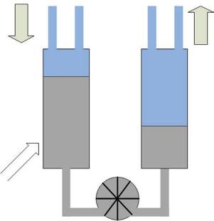
A simplified two-stage MHHC system is illustrated in Figure 1.6. The compression cycle can be summarized as follows:
Step 1: Valve No.1 opens and the low-pressure electrolyzer is attached to the first-stage reactor. When Valve No.1 opens, the first stage absorbs hydrogen in low pressure from the
supplier until the hydrogenation process ends. Then Valve No.1 closes and the first-stage reactor is in equilibrium.
Step 2: A sensible heating process of the first stage reactor occurs at a predefined high temperature (TH) in order to increase the pressure inside the tank and prepare the system for the upcoming coupling.
Step 3: Valve No.2 opens between the tanks of the first stage and the second stage, where the temperature of the firststage reactor is high (TH) and the temperature of the second stage is low (TL); thus, the released hydrogen from the first stage enters the second stage and is absorbed by the secondstage alloy. At the end of this process, Valve No. 2 closes.
Step 4: Another sensible heating process takes place at a predefined high temperature (TH) to increase the pressure inside the second-stage reactor.
Step 5: Valve No.3 opens and pressure hydrogen is stored in a high-pressure tank, while reactor 1 is prepared for the next compression cycle.
The above steps can also be described by the van’t Hoff diagrams for the first- and second-stage materials, as depicted in Figure 1.7a. The red lines correspond to the sensible heating process for each reactor, the black dashed line to the hydrogenation process for both stages and the black solid line to the dehydrogenation process respectively. It is essential that the material selection should fulfill certain criteria in order to ensure that the operation of the compression system will be safe and efficient. According to Figure 1.7b, the plateau pressure for the hydrogenation process of the first-stage material should be sufficiently low in order for the material to be able to absorb the hydrogen from the low-pressure hydrogen supplier.
Figure 1.6 A simplified scheme of a two-stage metal hydride hydrogen compression system.
High delivery pressure
high temperature
low temperature
Supply pressure
Delivery pressure
Sensible heating
Coupling process
Second stage dehydrogenation
First stage dehydrogenation
Second stage hydrogenation
First stage hydrogenation
Figure 1.7 The van’t Hoff diagram describing the operation steps of a two-stage metal hydride hydrogen compressor (a) and P-c-T plot describing the operation steps of a twostage metal hydride hydrogen compressor (b).
Furthermore, it is important that the plateau pressure of the dehydrogenation process for the first-stage material should be higher than the plateau pressure for the hydrogenation of the second-stage material in order to ensure the presence of the pressure difference between the two reactors, which is going to act as the driving force to lead hydrogen from the first tank to the other. Finally, to achieve the highest compression ratio, the plateau pressure of the final stage must be as high as possible.
Table 1.2 Overview of solid hydrogen storage options.
Carbon and high surface area materials
Chemical hydrides
Activated charcoalsEncapsulated NaH
Nanotubes –Graphene
Graphite Nanofibers
Rechargeable hydrides
Alloys –Intermetallics
Chemical hydrides
Ammonia Borozane
LiH and MgH2 Slurries NanocrystallineAluminum Hydride
CaH2, LiAlH4, etc. Complex
1.4.2 Metal Hydrides
The first step for the understanding of the operation of a multistage MHHC system is the detailed analysis on the background of the metal hydrides. The storage of hydrogen in solid materials has the potential to become a safe and efficient way to store energy for stationary, mobile and portable applications. There are four main groups of suitable materials for solid-state hydrogen storage applications: carbon and other high surface area materials; H2O-reactive chemical hydrides; thermo-chemical hydrides; and rechargeable hydrides. Table 1.2 summarizes the potential materials of these groups. Special attention has been given to the rechargeable hydride family of materials [40]. Metal hydrides can store atomic hydrogen in the metallic crystal structure. In the case of interstitial metal hydrides, the molecular hydrogen in the gas phase splits into atomic hydrogen on the surface of the material and then it diffuses into the atomic structure of the host metal [41]. Many different metallic compounds exist that can absorb hydrogen in this manner. In most cases, however, the storage does not occur at moderate temperature and pressure for practical storage purposes and the mass of the absorbed hydrogen is only a small fraction of the mass of the host metal [42].
1.4.3 Thermodynamic Analysis of the Metal Hydride
Formation
1.4.3.1 Pressure-Composition-Temperature (P-c-T) Properties
The thermodynamic aspects of the hydride formation and information related to the thermodynamic properties of solid hydrides can be
Figure 1.8 P-c-T curves at different temperatures (a) and van’t Hoff plot (b). The upper left lattice represents the solid solution phase ( -phase), the lower left lattice represents the co-existence of the solid solution and the hydride phase (in the cycle) and finally the middle right lattice represents the hydride phase ( -phase).
extracted from the pressure-composition-temperature curve (P-c-T) [43].
Figure 1.8a illustrates typical isotherm curves of a reversible hydride. By measuring the changes in the hydrogen pressure and the corresponding changes of the hydrogen concentration in the metal at a predefined temperature, the P-c-T curve is constructed. Ideally, the P-c-T curves should present a flat plateau. The plateau results from the co-existence of a solid solution ( -phase) and the hydride phase ( -phase). The effect of temperature on the behavior of the isotherm curves is also depicted in Figure 1.8a. When the temperature increases, the plateau pressure also increases to higher levels until a critical temperature Tc. At temperatures higher than Tc, the plateau region disappears and the -phase coverts to the -phase continuously.
Initially, the metal dissolves only a small amount of hydrogen (<0.25 wt%), which creates a solid solution of hydrogen in the metal matrix and is called “α-phase” [44]. As the hydrogen pressure increases, the interactions between the atomic hydrogen and the metal atoms dominate locally and the nucleation of a new phase is initiated (β-phase). In the plateau region, the solid solution (α-phase) and the β-phase co-exist [45]. The length of
T3>T2>T1
the plateau region determines the amount of hydrogen that can be stored reversibly with a small pressure variation. This phenomenon is explained from the Gibbs phase rule [46]:
(1.1)
where F is the degree of freedom, is the number of phases and N is the number of chemical species. Thus, existence of one additional phase leads to the loss of a degree of freedom. When the stoichiometric hydride has formed, completely depleting the -phase, one additional degree of freedom is regained and the additional absorption of hydrogen will now require a large pressure increase.
The equilibrium pressure, defined as the mid-plateau pressure P eq, is related to the changes in enthalpy (ΔΗ) and entropy (ΔS) of the hydride formation/deformation as a function of temperature and is described by the van’t Hoff law:
where P is the pressure (Pa), R (J/molK) is the universal gas constant, and T(K) is the temperature. The value of enthalpy is an index of the metal hydride stability. The higher the absolute value of the enthalpy shows a high degree of stability of the hydride, low dissociation pressure and the requirement of rather elevated temperatures decomposition for hydrogen release [47]. By plotting the van’t Hoff diagram lnP vs 1/T (Figure 1.8b) the enthalpy can be calculated from the slope ( ΔΗ/R) and the entropy from the intersection with y-axis. The entropy term corresponds mostly to the dissociation from molecular hydrogen to atomic during the sorption.
1.4.3.2 Slope and Hysteresis
The hysteresis between the hydrogenation and the dehydrogenation process is a phenomenon where the plateau corresponds to the hydrogenation is at a higher pressure than the plateau for the dehydrogenation, forming a hysteresis loop, as shown in Figure 1.9.
One explanation for the hysteresis is that the accommodation of the elastic and plastic energies is not equal for the hydrogenation and dehydrogenation [48]. Another aspect explains the hysteresis in terms of coherent
Another random document with no related content on Scribd:
The Project Gutenberg eBook of The Trouvelot astronomical drawings manual
This ebook is for the use of anyone anywhere in the United States and most other parts of the world at no cost and with almost no restrictions whatsoever. You may copy it, give it away or re-use it under the terms of the Project Gutenberg License included with this ebook or online at www.gutenberg.org. If you are not located in the United States, you will have to check the laws of the country where you are located before using this eBook.
Title: The Trouvelot astronomical drawings manual
Author: E. L. Trouvelot
Release date: June 24, 2022 [eBook #68394]
Language: English
Original publication: United States: C. Scribner's sons, 1882, 1882
Credits: Laura Natal Rodrigues (Images generously made available by Hathi Trust Digital Library and Wikipedia Commons.)
*** START OF THE PROJECT GUTENBERG EBOOK THE TROUVELOT ASTRONOMICAL DRAWINGS MANUAL ***
E. L. TROUVELOT,
FORMERLY CONNECTED WITH THE OBSERVATORY OF HARVARD COLLEGE; FELLOW OF THE AMERICAN ACADEMY OF ARTS AND SCIENCES, AND MEMBER OF THE SELENO-GRAPHICAL SOCIETY OF GREAT BRITAIN; IN CHARGE OF A GOVERNMENT EXPEDITION TO OBSERVE THE TOTAL SOLAR ECLIPSE OF 1878.
CHARLES SCRIBNER'S SONS
INTRODUCTION
During a study of the heavens, which has now been continued for more than fifteen years, I have made a large number of observations pertaining to physical astronomy, together with many original drawings representing the most interesting celestial objects and phenomena.
With a view to making these observations more generally useful, I was led, some years ago, to prepare, from this collection of drawings, a series of astronomical pictures, which were intended to represent the celestial phenomena as they appear to a trained eye and to an experienced draughtsman through the
great modern telescopes, provided with the most delicate instrumental appliances. Over two years were spent in the preparation of this series, which consisted of a number of large drawings executed in pastel. In 1876, these drawings were displayed at the United States Centennial Exhibition at Philadelphia, forming a part of the Massachusetts exhibit, in the Department of Education and Science.
The drawings forming the present series comprise only a part of those exhibited at Philadelphia; but, although fewer in number, they are quite sufficient to illustrate the principal classes of celestial objects and phenomena.
While my aim in this work has been to combine scrupulous fidelity and accuracy in the details, I have also endeavored to preserve the natural elegance and the delicate outlines peculiar to the objects depicted; but in this, only a little more than a suggestion is possible, since no human skill can reproduce upon paper the majestic beauty and radiance of the celestial objects.
The plates were prepared under my supervision, from the original pastel drawings, and great care has been taken to make the reproduction exact.
The instruments employed in the observations, and in the delineation of the heavenly bodies represented in the series, have varied in aperture from 6 to 26 inches, according to circumstances, and to the nature of the object to be studied. The great Washington refractor, kindly placed at my disposal by the late Admiral C. H. Davis, has contributed to this work, as has also the 26 inch telescope of the University of Virginia, while in the hands of its celebrated constructors, Alvan Clark & Sons. The spectroscope used was made by Alvan Clark & Sons. Attached to it is an excellent diffraction grating, by Mr L. M. Rutherfurd, to whose kindness I am indebted for it.
Those unacquainted with the use of optical instruments generally suppose that all astronomical drawings are obtained by the photographic process, and are, therefore, comparatively easy to procure; but this is not true. Although photography renders valuable assistance to the astronomer in the case of the Sun and Moon, as proved by the fine photographs of these objects taken by M. Janssen and Mr. Rutherfurd; yet, for other subjects, its products are in general so blurred and indistinct that no details of any great value can be secured. A welltrained eye alone is capable of seizing the delicate details of structure and of configuration of the heavenly bodies, which are liable to be affected, and even rendered invisible, by the slightest changes in our atmosphere.
The method employed to secure correctness in the proportions of the original drawings is simple, but well adapted to the purpose in view. It consists in placing a fine reticule, cut on glass, at the common focus of the objective and the eyepiece, so that in viewing an object, its telescopic image, appearing projected on the reticule, can be drawn very accurately on a sheet of paper ruled with
corresponding squares. For a series of such reticules I am indebted to the kindness of Professor William A. Rogers, of the Harvard College Observatory
The drawings representing telescopic views are inverted, as they appear in a refracting telescope—the South being upward, the North downward, the East on the right, and the West on the left. The Comet, the Milky-Way, the Eclipse of the Moon, the Aurora Borealis, the Zodiacal Light and the Meteors are represented as seen directly in the sky with the naked eye. The Comet was, however, drawn with the aid of the telescope, without which the delicate structure shown in the drawing would not have been visible.
The plate representing the November Meteors, or so-called "Leonids," may be called an ideal view, since the shooting stars delineated, were not observed at the same moment of time, but during the same night. Over three thousand Meteors were observed between midnight and five o'clock in the morning of the day on which this shower occurred; a dozen being sometimes in sight at the same instant. The paths of the Meteors, whether curved, wavy, or crooked, and also their delicate colors, are in all cases depicted as they were actually observed.
In the Manual, I have endeavored to present a general outline of what is known, or supposed, on the different subjects and phenomena illustrated in the series. The statements made are derived either from the best authorities on physical astronomy, or from my original observations, which are, for the most part, yet unpublished.
The figures in the Manual relating to distance, size, volume, mass, etc., are not intended to be strictly exact, being only round numbers, which can, therefore, be more easily remembered.
It gives me pleasure to acknowledge that the experience acquired in making the astronomical drawings published in Volume VIII. of the Annals of the Harvard College Observatory, while I was connected with that institution, has been of considerable assistance to me in preparing this work; although no drawings made while I was so connected have been used for this series.
E. L. TROUVELOT
Cambridge, March, 1882.
INTRODUCTION LIST OF PLATES
CONTENTS
THE SUN
GENERAL REMARKS ON THE SUN
SUN-SPOTS AND VEILED SPOTS
SOLAR PROTUBERANCES
TOTAL ECLIPSE OF THE SUN
THE AURORAL AND ZODIACAL LIGHTS
THE AURORA BOREALIS
THE ZODIACAL LIGHT
THE MOON
THE MOON ECLIPSES OF THE MOON
THE PLANETS
THE PLANET MARS
THE PLANET JUPITER THE PLANET SATURN
COMETS AND METEORS
COMETS
SHOOTING-STARS AND METEORS
THE STELLAR SYSTEMS
THE MILKY-WAY OR GALAXY
THE STAR-CLUSTERS
THE NEBULÆ APPENDIX
LIST OF PLATES[1] PLATE
I. GROUP OF SUN-SPOTS AND VEILED SPOTS.
Observed June 17, 1875, at 7 h. 30m. A. M.
II. SOLAR PROTUBERANCES.
Observed May 5, 1873, at 9h. 40m. A. M.
III. TOTAL ECLIPSE OF THE SUN.
Observed July 29, 1878, at Creston, Wyoming Territory
IV. AURORA BOREALIS.
As observed March 1, 1872, at 9h. 25m. P. M.
V. THE ZODIACAL LIGHT.
Observed February 20, 1876.
VI. MARE HUMORUM.
From a study made in 1875.
VII. PARTIAL ECLIPSE OF THE MOON.
Observed October 24, 1874.
VIII. THE PLANET MARS.
Observed September 3, 1877, at 11h. 55m. P. M.
IX. THE PLANET JUPITER.
Observed November 1, 1880, at 9h. 30m. P. M.
X. THE PLANET SATURN.
Observed November 30, 1874, at 5th. 50m. P. M.
XI. THE GREAT COMET OF 1881.
Observed on the night of June 25-26, at 1h. 30m. A. M.
XII. THE NOVEMBER METEORS.
As observed between midnight and 3 o'clock A. M., on the night of November 13-14, 1868.
XIII. PART OF THE MILKY-WAY.
From a study made during the years 1874, 1875 and 1876.
XIV. STAR-CLUSTER IN HERCULES.
From a study made in June, 1877.
XV. THE GREAT NEBULA IN ORION.
From a study made in the years 1873-76.
[1]For Key to the Plates, see Appendix
Reproduced from the Original Drawings, by Armstrong & Company, Riverside Press, Cambridge, Mass.
GENERAL REMARKS ON THE SUN
The Sun, the centre of the system which bears its name, is a self-luminous sphere, constantly radiating heat and light.
Its apparent diameter, as seen at its mean from the Earth, subtends an angle of 32', or a little over half a degree. A dime, placed about six feet from the eye, would appear of the same proportions, and cover the Sun's disk, if projected upon it.
That the diameter of the Sun does not appear larger, is due to the great distance which separates us from that body Its distance from the Earth is no less than 92,000,000 miles. To bridge this immense gap, would require 11,623 globes like the Earth, placed side by side, like beads on a string.
The Sun is an enormous sphere whose diameter is over 108 times the diameter of our globe, or very nearly 860,000 miles. Its radius is nearly double the distance from the Earth to the Moon. If we suppose, for a moment, the Sun to be hollow, and our globe to be placed at the centre of this immense spherical shell, not only could our satellite revolve around us at its mean distance of 238,800 miles, as now, but another satellite, placed 190,000 miles farther than the Moon, could freely revolve likewise, without ever coming in contact with the solar envelope.
The circumference of this immense sphere measures 2,800,000 miles. While a steamer, going at the rate of 300 miles a day, would circumnavigate the Earth in 83 days, it would take, at the same rate, nearly 25 years to travel around the Sun.
The surface of the Sun is nearly 12,000 times the surface of the Earth, and its volume is equal to 1,300,000 globes like our own. If all the known planets and satellites were united in a single mass, 600 such compound masses would be needed to equal the volume of our luminary
Although the density of the Sun is only one-quarter that of the Earth, yet the bulk of this body is so enormous that, to counterpoise it, no less than 314,760 globes like our Earth would be required.
The Sun uniformly revolves around its axis in about 25½ days. Its equator is inclined 7° 15' to the plane of the ecliptic, the axis of rotation forming, therefore, an angle of 82° 45' with the same plane. As the Earth revolves about the Sun in the same direction as that of the Sun's rotation, the apparent time of this rotation, as seen by a terrestrial spectator, is prolonged from 25½ days to about 27 days and 7 hours.
The rotation of the Sun on its axis, like that of the Earth and the other planets, is direct, or accomplished from West to East. To an observer on the Earth, looking directly at the Sun, the rotation of this body is from left to right, or from East to West.
The general appearance of the Sun is that of an intensely luminous disk, whose limb, or border, is sharply defined on the heavens. When its telescopic image is projected on a screen, or fixed on paper by photography, it is noticed that its disk is not uniformly bright throughout, but is notably more luminous in its central parts. This phenomenon is not accidental, but permanent, and is due in reality to a very rare but extensive atmosphere which surrounds the Sun, and absorbs the light which that body radiates, proportionally to its thickness, which, of course, increases towards the limb, to an observer on the Earth.
THE ENVELOPING LAYERS OF THE SUN
The luminous surface of the Sun, or that part visible at all times, and which forms its disk, is called the Photosphere, from the property it is supposed to possess of generating light. The photosphere does not extend to a great depth below the luminous surface, but forms a comparatively thin shell, 3,000 or 4,000 miles thick, which is distinct from the interior parts, above which it seems to be kept in suspense by internal forces. From the observations of some astronomers it would appear that the diameter of the photosphere is subject to slight variations, and, therefore, that the solar diameter is not a constant quantity. From the nature of this envelope, such a result does not seem at all impossible, but rather probable.
Immediately above the photosphere lies a comparatively thin stratum, less than a thousand miles in thickness, called the Reversing Layer. This stratum is composed of metallic vapors, which, by absorbing the light of particular refrangibilities emanating from the photosphere below, produces the dark Fraunhofer lines of the solar spectrum.
Above the reversing layer, and resting immediately upon it, is a shallow, semitransparent gaseous layer, which has been called the Chromosphere, from the fine tints which it exhibits during total eclipses of the Sun, in contrast with the colorless white light radiated by the photosphere below. Although visible to a certain extent on the disk, the chromosphere is totally invisible on the limb, except with the spectroscope, and during eclipses, on account of the nature of its light, which is mainly monochromatic, and too feeble, compared with that emitted by the photosphere, to be seen.
The chromospheric layer, which has a thickness of from 3,000 to 4,000 miles, is uneven, and is usually upheaved in certain regions, its matter being transported to considerable elevations above its general surface, apparently by some internal forces. The portions of the chromosphere thus lifted up, form curious and complicated figures, which are known under the names of Solar Protuberances, or Solar Flames.
Above the chromosphere, and rising to an immense but unknown height, is the solar atmosphere proper, which is only visible during total eclipses of the Sun, and which then surrounds the dark body of the Moon with the beautiful rays and glorious nimbus, called the Corona
These four envelopes: the photosphere, the reversing layer, the chromosphere, and the corona, constitute the outer portions of our luminary
Below the photosphere little can be seen, although it is known, as will appear below, that at certain depths cloud-like forms exist, and freely float in an interior atmosphere of invisible gases. Beyond this all is mystery, and belongs to the domain of hypothesis.
STRUCTURE OF THE PHOTOSPHERE AND CHROMOSPHERE
The apparent uniformity of the solar surface disappears when it is examined with a telescope of sufficient aperture and magnifying powers. Seen under good atmospheric conditions, the greater part of the solar surface appears mottled with an infinite number of small, bright granules, irregularly distributed, and separated from each other by a gray-tinted background.
These objects are known under different names. The terms granules and granulations answer very well for the purpose, as they do not imply anything positive as to their form and true nature. They have also been called Luculœ, Rice Grains, Willow Leaves, etc., by different observers.
Although having different shapes, the granulations partake more or less of the circular or slightly elongated form. Their diameter, which varies considerably, has been estimated at from 0".5 to 3", or from 224 to 1,344 miles. The granulations which attain the largest size appear, under good atmospheric conditions, to be composed of several granules, closely united and forming an irregular mass, from which short appendages protrude in various directions.
The number of granulations on the surface of the Sun varies considerably under the action of unknown causes. Sometimes they are small and very numerous, while at other times they are larger, less numerous, and more widely separated. Other things being equal, the granulations are better seen in the central regions of the Sun than they are near the limb.
Usually the granulations are very unstable; their relative position, form, and size undergoing continual changes. Sometimes they are seen to congregate or to disperse in an instant, as if acting under the influence of attractive and repulsive forces; assembling in groups or files, and oftentimes forming capricious figures which are very remarkable, but usually of short duration. In an area of great solar
disturbances, the granulations are often stretched to great distances, and form into parallel lines, either straight, wavy, or curved, and they have then some resemblance to the flowing of viscous liquids.
The granulations are usually terminated either by rounded or sharply pointed summits, but they do not all rise to the same height, as can be ascertained with the spectroscope when they are seen sidewise on the limb. In the regions where they are most abundant, they usually attain greater elevations, and when observed on the limb with the spectroscope, they appear as slender acute flames.
The granulations terminated by sharply-pointed crests, although observed in all latitudes, seem to be characteristic of certain regions. A daily study of the chromosphere, extending over a period of ten years, has shown me that the polar regions are rarely ever free from these objects, which are less frequent in other parts of the Sun. In the polar regions they are sometimes so abundant that they completely form the solar limb These forms of granulation are comparatively rare in the equatorial zones, and when seen there, they never have the permanency which they exhibit in the polar regions. When observed in the equatorial regions, they usually appear in small groups, in the vicinity of sun spots, or they are at least enclosed in areas of disturbances where such spots are in process of formation. In these regions they often attain greater elevations than those seen in high latitudes.
As we are certain that in the equatorial zones these slender flames (i. e., granulations) are a sure sign of local disturbance, it may be reasonably supposed that the same kind of energy producing them nearly always prevails in the polar regions, although it is there much weaker, and never reaches beyond certain narrow limits.
Studied with the spectroscope, the granulations are found to be composed in the main of incandescent hydrogen gas, and of an unknown substance provisionally called "helium." Among the most brilliant of them are found traces of incandescent metallic vapors, belonging to various substances found on our globe.
The chromosphere is not fixed, but varies considerably in thickness in its different parts, from day to day. Its thickness is usually greater in the polar regions, where it sometimes exceeds 6,700 miles. In the equatorial regions the chromosphere very rarely attains this height, and when it does, the rising is local and occupies only a small area. In these regions it is sometimes so shallow that its depth is only a few seconds, and is then quite difficult to measure. These numbers give, of course, the extreme limits of the variations of the chromosphere; but, nearly always, it is more shallow in the equatorial regions; and, as far as my observations go, the difference in thickness between the polar and equatorial zones is greater in years of calm than it is in years of great solar activity But ten
years of observation are not sufficient to warrant any definite conclusions on this subject.
There is undoubtedly some relation between the greater thickness of the chromosphere in the polar regions, and the abundance and permanence of the sharply-pointed granulations observed in the same regions. This becomes more evident when we know that the appearance of similarly-pointed flames in the equatorial zones is always accompanied with a local thickening of the chromosphere. The thickening in the polar regions may be only apparent, and not due to a greater accumulation of chromospheric gases there; but may be caused by some kind of repulsive action or polarity, which lifts up and extends the summit of the granulations in a manner similar to the well-known mode of electric repulsion and polarity.
As it seems very probable that the heat and light emanating from the Sun are mainly generated at the base of the granulations, in the filamentary elements composing the chromosphere and photosphere, it would follow that, as the size and number of these objects constantly vary, the amount of heat and light emitted by the Sun should also vary in the same proportion.
The granulations of the solar surface are represented on Plate I., and form the general background to the group of Sun-spots forming the picture.
THE FACULÆ
Although the solar surface is mainly covered with the luminous granulations and the grayish background above described, it is very rare that its appearance is so simple and uniform as already represented. For the most part, on the contrary, it is diversified by larger, brighter, and more complicated forms, which are especially visible towards the border of the Sun. Owing to their extraordinary brilliancy, these objects have been called Faculœ (torches).
Although the faculæ are very seldom seen well beyond 50 heliocentric degrees from the limb, yet they exist, and are as numerous in the central parts of the disk as they are towards the border; since they form a part of the solar surface, and participate in its movement of rotation. Their appearance near the limb has been attributed to the effect of absorption produced by the solar atmosphere on the light from the photosphere; but this explanation seems inadequate, and does not solve the problem. The well-known fact that the solar protuberances—which are in a great measure identical with the faculæ—are much brighter at the base than they are at the summit, perhaps gives a clue to the explanation of the phenomenon; especially since we know that, in general, the summit of the protuberances is considerably broader than their base. When
these objects are observed in the vicinity of the limb, they present their brightest parts to the observer, since, in this position, they are seen more or less sidewise; and, therefore, they appear bright and distinct. But as the faculæ recede from the limb, their sides, being seen under a constantly decreasing angle, appear more and more foreshortened; and, therefore, these objects grow less bright and less distinct, until they finally become invisible, when their bases are covered over by the broad, dusky summit generally terminating the protuberances.
The faculæ appear as bright and luminous masses or streaks on the granular surface of the Sun, but they differ considerably in form and size. Two types at least are distinguishable. In their simplest form they appear either as isolated white spots, or as groups of such spots covering large surfaces, and somewhat resembling large flakes of snow. In their most characteristic types they appear as intensely luminous, heavy masses, from which, in most cases, issue intricate ramifications, sometimes extending to great distances. Generally, the ramifications issuing from the masses of faculæ have their largest branches directed in the main towards the eastern limb of the Sun. Some of these branches have gigantic proportions. Occasionally they extend over 60° and even 80° of the solar surface, and, therefore, attain a length of from 450,000 to 600,000 miles.
Although the faculæ may be said to be seen everywhere on the surface of the Sun, there is a vast difference in different regions, with regard to their size, number, and brilliancy They are largest, most abundant, and brightest on two intermediate zones parallel to the solar equator, and extending 35° or 40° to the north and to the south of this line. The breadth of these zones varies considerably with the activity of the solar forces. When they are most active, the faculæ spread on either side, but especially towards the equator, where they sometimes nearly meet those of the other zone. In years of little solar activity the belts formed by the faculæ are very narrow—the elements composing them being very few and small, although they never entirely disappear
The faculæ are very unstable, and are constantly changing: those of the small types sometimes form and vanish in a few minutes. When an area of disturbance of the solar surface is observed for some time, all seems in confusion; the movements of the granulations become unusually violent; they congregate in all sorts of ways, and thus frequently form temporary faculæ. Action of this kind is, for the most part, peculiar to the polar regions of the Sun.
The larger faculæ have undoubtedly another origin, as they seem to be mainly formed by the ejection of incandescent gases and metallic vapors from the interior of the photosphere. In their process of development some of the heavy masses of faculæ are swollen up to great heights, being torn in all sorts of ways, showing large rents and fissures through which the sight can penetrate.
Very few faculæ are represented in Plate I.; several streaks are shown at the upper left-hand corner, some appearing as whitish ramifications among the granulations representing the general solar surface.
SUN-SPOTS AND VEILED SPOTS
PLATE I
Besides the brilliant faculæ already described, much more conspicuous markings, though of a totally different character, are very frequently observed on the Sun On account of their darkish appearance, which is in strong contrast with the white envelope of our luminary, these markings were called Maculæ, or Sunspots, by their earlier observers.
The Sun-spots are not equally distributed on the solar surface; but like the faculæ, to which they are closely related, they occupy two zones—one on each side of the equator These zones are comprised between 10° and 35° of north latitude, and 10° and 35° of south latitude. Between these two zones is a belt 20° in width, where the Sun-spots are rarely seen.
Above the latitudes 35° north and south, the Sun-spots are rare, and it is only occasionally, and during years of great solar activity, that they appear in these regions; in only a few cases have spots of considerable size been seen there. A few observers, however, have seen spots as far as 40° and 50 from the equator; and La Hire even observed one in 70° of north latitude; but these cases are exceedingly rare. It is not uncommon, however, to see very small spots, or groups of such spots, within 8° or 10° from the poles.
The activity of the Sun is subject to considerable fluctuation, and accordingly the Sun-spots vary in size and number in different years. During some years they are large, complicated, and very numerous; while in others they are small and scarce, and are sometimes totally absent for weeks and months together The fluctuations in the frequency of Sun-spots are supposed to be periodical in their character, although their periods do not always appear to recur at exactly regular intervals. Sometimes the period is found to be only nine years, while at other times it extends to twelve years. The period generally adopted now is 11 ⅒ years, nearly; but further investigations are needed to understand the true nature of the phenomenon.
The number of Sun-spots does not symmetrically augment and diminish, but the increase is more rapid than the diminution.
The period of increase is only about four years, while that of decrease is over seven years; each period of Sun-spot maximum being nearer the preceding period of Sun-spot minimum than it is to that next following.
The cause of these fluctuations in the solar energy is at present wholly unknown. Some astronomers, however, have attributed it to the influence of the planets Venus and Jupiter, the period of revolution of the latter planet being not much longer than the Sun-spot period; but this supposition lacks confirmation from direct observations, which, so far, do not seem to be in favor of the hypothesis. At the present time the solar activity is on the increase, and the Sunspots will probably reach their maximum in 1883. The last minimum occurred in 1879, when only sixteen small groups of spots were observed during the whole year.
Sun-spots vary in size and appearance; but, unless they are very small, in which case they appear as simple black dots, they generally consist of two distinct and well-characterized parts, nearly always present. There is first, a central part, much darker than the other, and sharply divided from it, called the "Umbra;" second, a broad, irregular radiated fringe of lighter shade, completely surrounding the first, and called the "Penumbra."
Reduced to its simplest expression, a Sun-spot is a funnel-shaped opening through the chromosphere and the photosphere. The inner end of the funnel, or opening, gives the form to the umbra, while its sloping sides form the penumbra.
The umbra of Sun-spots, whose outlines approximately follow the irregularities of the penumbral fringe, has a diameter which generally exceeds the width of the penumbral ring. Sometimes it appears uniformly black throughout; but it is only so by contrast, as is proved when either Mercury or Venus passes near a spot during a transit over the Sun's disk. The umbra then appears grayish, when compared with the jet-black disk of the planet.
The umbra of spots is rarely so simple as just described; but it is frequently occupied, either partly or wholly, by grayish and rosy forms, somewhat resembling loosely-entangled muscular fibres. These forms have been called the Gray and Rosy Veils Frequently these veils appear as if perforated by roundish black holes, improperly called Nuclei, which permit the sight to penetrate deeper into the interior To all appearance the gray and rosy veils are of the same nature as the chromosphere and the faculæ, and are therefore mainly composed of hydrogen gas.
Whatever can be known about the interior of the Sun, must be learned from the observations of these openings, which are comparatively small. But whatever this interior may be, we certainly know that it is not homogeneous. Apparently, the Sun is a gigantic bubble, limited by a very thin shell. Below this shell exists a large open space filled with invisible gases, in which, through the openings constituting the Sun-spots, the gray and rosy veils described above are occasionally seen floating.
The fringe forming the penumbra of spots is much more complicated than the umbra. In its simpler form, it is composed of a multitude of bright, independent
filaments of different forms and sizes, partly projecting one above the other, on the sloping wall of the penumbra, from which they seem to proceed. Seen from the Earth, these filaments have somewhat the appearance of thatched straw, converging towards the centre of the umbra. It is very rare, however, that the convergence of the penumbral filaments is regular, and great confusion sometimes arises from the entanglement of these filaments. Some of these elements appear straight, others are curved or loop-shaped; while still others, much larger and brighter than the rest, give a final touch to this chaos of filaments, from which results the general thatched and radiating appearance of the penumbra.
The extremities of the penumbral filaments, especially of those forming the border of the umbra, are usually club-shaped and appear very brilliant, as if these elements had been superheated by some forces escaping through the opening of the spots.
Besides these characteristics, the Sun-spots have others, which, although not always present, properly belong to them. Comparatively few spots are so simple as the form just described. Very frequently a spot is accompanied by brilliant faculæ, covering part of its umbra and penumbra, and appearing to form a part of the spot itself.
When seen projected over Sun-spots, the faculæ appear intensely bright, and from these peculiarities they have been called Luminous Bridges. They are, in fact, bridges, but in most cases they are at considerable heights above the spots, kept there by invisible forces. When such spots with luminous bridges approach the Sun's limb, it is easy to see, by the rapid apparent displacement which they undergo, that they are above the general level.
When the spots are closing up, the inverse effect is sometimes observed. On several occasions, I have seen huge masses of faculæ advance slowly over the penumbra of a spot and fall into the depths of the umbra, resembling gigantic cataracts. I have seen narrow branches of faculæ, which, after having fallen to great depths in the umbra, floated across it and disappeared under the photosphere on the opposite side. I have also seen luminous bridges, resembling cables, tightly stretched across the spots, slackening slowly, as if loosened at one end, and gently curving into the umbra, where they formed immense loops, large enough to receive our globe.
It is to be remarked that, in descending under the photospheric shell, the bright faculæ and the luminous bridges gradually lose their brilliancy. At first they appear grayish, but in descending farther they assume more and more the pink color peculiar to the rosy veils. The pinkish color acquired by the faculæ when they reach a certain depth under the photosphere, is precisely the color of the chromosphere and of the solar protuberances, as seen during total eclipses of the Sun—a fact which furnishes another proof that the faculæ are of the same nature as the protuberances.
I record here an observation which, at first sight, may appear paradoxical; but which seems, however, to be of considerable importance, as it shows unmistakably that the solar light is mainly, if not entirely, generated on its surface, or at least very near to it. On May 26, 1878, I observed a large group of Sunspots at a little distance from the east limb of the Sun. The spot nearest to the limb was partly covered over on its eastern and western sides by bright and massive faculæ which concealed about two-thirds of the whole spot, only a narrow opening, running from north to south, being left across the middle of the spot. Owing to the rotundity of the Sun, the penumbra of this spot, although partly covered by the faculæ, could, however, be seen on its eastern side, since the sight of the observer could there penetrate sidewise under the faculæ. Upon that part of the penumbra appeared a strong shadow, representing perfectly the outline of the facular mass situated above it. The phenomenon was so apparent that no error of observation was possible, and a good drawing of it was secured. If this faculæ had been as bright beneath as it was above, it is evident that no shadow could have been produced; hence the light of these faculæ must have been mainly generated on or very near their exterior surfaces. This, with the wellproved fact that the bright faculæ lose their light in falling into the interior of the Sun, seems to suggest the idea that the bright light emitted by the faculæ, and very probably all the solar light, can be generated only on its surface; the presence of the coronal atmosphere being perhaps necessary to produce it. Several times before this observation, I had suspected that some faculæ were casting a shadow, but as this seemed so improbable, my attention was not awakened until the phenomenon became so prominent that it could not escape notice.
With due attention, some glimpses of the phenomenon can frequently be observed through the openings of some of the faculæ projecting over the penumbra of Sun-spots. It is very seldom that the structure of the penumbra is seen through such openings, which usually appear as dark as the umbra of the large spots, although they do not penetrate through the photosphere like the latter. It is only when the rents in the faculæ are numerous and quite large, that the penumbral structure is recognized through them. Since these superficial rents in the faculæ do not extend through the photosphere, and appear black, it seems evident that the penumbra seen through them cannot be as bright as it is when no faculæ are projected upon it, and therefore that the faculæ intercept light from the exterior surface, which would otherwise reach the penumbra.
While the matter forming the faculæ sometimes falls into the interior of the Sun, the same kind of matter is frequently ejected in enormous quantities, and with great force, from the interior, through the visible and invisible openings of the photosphere, and form the protuberances described in the following section of this manual (Solar protuberances) It is not only the incandescent hydrogen gas or the metallic vapors which are thus ejected, but also cooler hydrogen gas, which sometimes appears as dark clouds on the solar surface. On December 12, 1875,


