ALL RIGHTS RESERVED. No part of this work covered by the copyright herein may be reproduced or distributed in any form or by any means, except as permitted by U.S. copyright law, without the prior written permission of the copyright owner.
For product information and technology assistance, contact us at Cengage Learning Customer & Sales Support, 1-800-354-9706. For permission to use material from this text or product, submit all requests online at www.cengage.com/permissions Further permissions questions can be emailed to permissionrequest@cengage.com.
Cengage Learning is a leading provider of customized learning solutions with employees residing in nearly 40 different countries and sales in more than 125 countries around the world. Find your local representative at www.cengage.com
Cengage Learning products are represented in Canada by Nelson Education Ltd.
To learn more about Cengage Learning Solutions, visit www.cengage.com/engineering
Purchase any of our products at your local college store or at our preferred online store www.cengagebrain.com.
Preface x About the Author xvi
Chapter 1
Voltage,
Current, Power, and SourCeS 1
1.1 Introduction 1
1.2 International System of Units 1
1.3 Charge, Voltage, Current, and Power 4
1.3.1 Electric Charge 4
1.3.2 Electric Field 4
1.3.3 Voltage 5
1.3.4 Current 7
1.3.5 Power 9
1.4 Independent Sources 10
1.4.1 Direct Current Sources and Alternating Current Sources 11
1.5 Dependent Sources 15
1.5.1 Voltage-Controlled Voltage Source (VCVS) 16
1.5.2 Voltage-Controlled Current Source (VCCS) 16
1.5.3 Current-Controlled Voltage Source (CCVS) 16
1.5.4 Current-Controlled Current Source (CCCS) 16
1.6 Elementary Signals 17
1.6.1 Dirac Delta Function 17
1.6.2 Step Function 19
1.6.3 Ramp Function 21
1.6.4 Exponential Decay 23
1.6.5 Rectangular Pulse and Triangular Pulse 24
Summary 27
PrOBLEmS 27
Chapter 2
CirCuit lawS 31
2.1 Introduction 31
2.2 Circuit 31
2.3 Resistor 33
2.4 Ohm’s Law 35
2.5 Kirchhoff’s Current Law (KCL) 38
Kirchhoff’s Voltage Law (KVL) 46
Series and Parallel Connection of Resistors 53
2.7.1 Series Connection of Resistors 53
2.7.2 Parallel Connection of Resistors 58 2.8 Voltage Divider Rule 74
2.8.1 Wheatstone Bridge 80
2.9 Current Divider Rule 82
2.10 Delta-Wye (D-Y) Transformation and Wye-Delta (Y-D) Transformation 91
2.11 PSpice and Simulink 100
2.11.1 Simulink 104
Summary 104
PrOBLEmS 105
Chapter 3
CirCuit analySiS MethodS 117
3.1 Introduction 117
3.2 Nodal Analysis 118
3.3 Supernode 142
3.4 Mesh Analysis 153
3.5 Supermesh 175
3.6 PSpice and Simulink 190
3.6.1 PSpice 190
3.6.2 VCVS 190
3.6.3 VCCS 191
3.6.4 CCVS 192
3.6.5 CCCS 193
3.6.6 Simulink 193
Summary 194
PrOBLEmS 194
Chapter 4
CirCuit theoreMS 208
4.1 Introduction 208
4.2 Superposition Principle 209
4.3 Source Transformations 221
4.4 Thévenin’s Theorem 234
4.4.1 Finding the thévenin equivalent Voltage Vth 235
4.4.2 Finding the thévenin equivalent Resistance Rth 235
4.5 Norton’s Theorem 263
4.5.1 Finding the norton equivalent Current In 264
4.5.2 Finding the norton equivalent Resistance Rn 264
4.5.3 Relation Between the thévenin equivalent Circuit and the norton equivalent Circuit 264
20.3.1 Conversion of z-Parameters to All the other Parameters 1489
20.3.2 Conversion of z-Parameters to y-Parameters 1489
20.3.3 Conversion of z-Parameters to ABCD Parameters 1490
20.3.4 Conversion of z-Parameters to b-Parameters 1491
20.3.5 Conversion of z-Parameters to h-Parameters 1491
20.3.6 Conversion of z-Parameters to g-Parameters 1492
20.3.7 Conversion of y-Parameters to All the other Parameters 1493
20.3.8 Conversion of h-Parameters to All the other Parameters 1494
20.3.9 Conversion of g-Parameters to All the other Parameters 1494
20.3.10 Conversion of ABCD Parameters to All the other Parameters 1495
20.3.11 Conversion of b-Parameters to All the other Parameters 1496
20.4 Interconnection of Two-Port Circuits 1500
20.4.1 Cascade Connection 1500
20.4.2 Series Connection 1502
20.4.3 Parallel Connection 1505
20.4.4 Series-Parallel Connection 1507
20.4.5 Parallel-Series Connection 1508
20.4.6 Cascade Connection for b-Parameters 1508
20.5 PSpice and Simulink 1509
Summary 1512
PrOBLEmS 1513
Answers to Odd-Numbered Questions 1517
Index 1548
Preface
This book is intended to be an introductory text on the subject of electric circuits. It provides simple explanations of the basic concepts, followed by simple examples and exercises. When necessary, detailed derivations for the main topics and examples are given to help readers understand the main ideas. MATLAB is a tool that can be used effectively in Electric Circuits courses. In this text, MATLAB is integrated into selected examples to illustrate its use in solving circuit problems. MATLAB can be used to check the answers or solve more complex circuit problems. This text is written for a two-semester sequence or a three-quarters sequence on electric circuits.
Suggested Course Outlines
The following is a list of topics covered in a typical Electric Circuits courses, with suggested course outlines.
one-SeMeSter or -Quarter CourSe
If Electric Circuits is offered as a one-semester or one-quarter course, Chapters 1 through 12 can be taught without covering, or only lightly covering, sections 1.6, 2.10, 2.11, 3.6, 4.7, 5.6, 5.7, 5.8, 6.7, 7.6, 7.7, 8.8, 8.9, 9.9, 9.10, 10.12, 11.7, 12.5, 12.6, and 12.7.
two-SeMeSter or -Quarter CourSeS
For two-semester Electric Circuit courses, Chapters 1 through 8, which cover dc circuits, op amps, and the responses of first-order and second-order circuits, can be taught in the first semester. Chapters 9 through 20, which cover alternating current (ac) circuits, Laplace transforms, circuit analysis in the s-domain, two-port circuits, analog filter design and implementation, Fourier series, and Fourier transform, can then be taught in the second semester.
three-Quarter CourSeS
For three-quarter Electric Circuit courses, Chapters 1 through 5, which cover dc circuits and op amps, can be taught in the first quarter; Chapters 6 through 13, which cover the responses of first-order and second-order circuits and ac circuits, can be taught in the second quarter, and Chapters 14 through 20, which cover Laplace transforms, circuit analysis in the s-domain, two-port circuits, analog filter design and implementation, Fourier series, and Fourier transform, can be taught in the third quarter.
Depending on the catalog description and the course outlines, instructors can pick and choose the topics covered in the courses that they teach. Several features of this text are listed next.
Features
After a topic is presented, examples and exercises follow. Examples are chosen to expand and elaborate the main concept of the topic. In a step-by-step approach, details are worked out to help students understand the main ideas.
In addition to analyzing RC, RL, and RLC circuits connected in series or parallel in the time domain and the frequency domain, analyses of circuits different from RC, RL, and RLC circuits and connected other than in series and parallel are provided. Also, general input signals that are different from unit step functions are included in the analyses.
In the analog filter design, the specifications of the filter are translated into its transfer function in cascade form. From the transfer function, each section can be designed with appropriate op amp circuits. The normalized component values for each section are found by adopting a simplification method (equal R equal C or unity gain). Then, magnitude scaling and frequency scaling are used to find the final component values. The entire design procedure, from the specifications to the circuit design, is detailed, including the PSpice simulation used to verify the design.
Before the discussion of Fourier series, orthogonal functions and the representation of square integrable functions as a linear combination of a set of orthogonal functions are introduced. The set of orthogonal functions for Fourier series representation consists of cosines and sines. The Fourier coefficients for the square pulse train, triangular pulse train, sawtooth pulse train, and rectified sines and cosines are derived. The Fourier coefficients of any variation of these waveforms can be found by applying the time-shifting property and finding the dc component.
MATLAB can be an effective tool in solving problems in electric circuits. Simple functions such as calculating the equivalent resistance or impedance of parallel connection of resistors, capacitors, and inductors; conversion from Cartesian coordinates to polar coordinates; conversion from polar coordinates to Cartesian coordinates; conversion from the wye configuration to delta configuration; and conversion from delta configuration to wye configuration provide accurate answers in less time. These simple functions can be part of scripts that enable us to find solutions to typical circuit problems.
The complexity of taking the inverse Laplace transforms increases as the order increases. MATLAB can be used to solve equations and to find integrals, transforms, inverse transforms, and transfer functions. The application of MATLAB to circuit analysis is demonstrated throughout the text when appropriate. For example, after finding inverse Laplace transforms by hand using partial fraction expansion, answers from MATLAB are provided as a comparison.
Examples of circuit simulation using OrCAD PSpice and Simulink are given at the end of each chapter. Simulink is a tool that can be used to perform circuit simulations. In Simulink, physical signals can be converted to Simulink signals and vice versa. Simscapes include many blocks that are related to electric circuits. Simulink can be used in computer assignments or laboratory experiments.
The Instructor’s Solution Manual for the exercises and end-of-chapter problems is available for instructors. This manual includes MATLAB scripts for selected problems as a check on the accuracy of the solutions by hand.
Overview of Chapters
In Chapter 1, definitions of voltage, current, power, and energy are given. Also, independent voltage source and current source are introduced, along with dependent voltage sources and current sources.
In Chapter 2, nodes, branches, meshes, and loops are introduced. Ohm’s law is explained. Kirchhoff’s current law (KCL), Kirchhoff’s voltage law (KVL), the voltage divider rule, and the current divider rule are explained with examples.
In Chapter 3, nodal analysis and mesh analysis are discussed in depth. The nodal analysis and mesh analysis are used extensively in the rest of the text.
Chapter 4 introduces circuit theorems that are useful in analyzing electric circuits and electronic circuits. The circuit theorems discussed in this chapter are the superposition
principle, source transformations, Thévenin’s theorem, Norton’s theorem, and maximum power transfer.
Chapter 5 introduces op amp circuits. Op amp is a versatile integrated circuit (IC) chip that has wide-ranging applications in circuit design. The concept of the ideal op amp model is explained, along with applications in sum and difference, instrumentation amplifier, and current amplifier. Detailed analysis of inverting configuration and noninverting configuration is provided.
In Chapter 6, the energy storage elements called capacitors and inductors are discussed. The current voltage relation of capacitors and inductors are derived. The energy stored on the capacitors and inductors are presented.
In Chapter 7, the transformation of RC and RL circuits to differential equations and solutions of the first-order differential equations to get the responses of the circuits are presented. In the general first-order circuits, the input signal can be dc, ramp signal, exponential signal, or sinusoidal signal.
In Chapter 8, the transformation of series RLC and parallel RLC circuits to the secondorder differential equations, as well as solving the second-order differential equations to get the responses of the circuits are presented. In the general second-order circuits, the input signal can be dc, ramp signal, exponential signal, or sinusoidal signal.
Chapter 9 introduces sinusoidal signals, phasors, impedances, and admittances. Also, transforming ac circuits to phasor-transformed circuits is presented, along with analyzing phasor transformed circuits using KCL, KVL, equivalent impedances, delta-wye transformation, and wye-delta transformation.
The analysis of phasor-transformed circuits is continued in Chapter 10 with the introduction of the voltage divider rule, current divider rule, nodal analysis, mesh analysis, superposition principle, source transformation, Thévenin equivalent circuit, Norton equivalent circuit, and transfer function. This analysis is similar to the one for resistive circuits with the use of impedances.
Chapter 11 presents information on ac power. The definitions of instantaneous power, average power, reactive power, complex power, apparent power, and power factor are also given, and power factor correction is explained with examples.
As an extension of ac power, the three-phase system is presented in Chapter 12. The connection of balanced sources (wye-connected or delta-connected) to balanced loads (wye-connected or delta connected) are presented, both with and without wire impedances.
Magnetically coupled circuits, which are related to ac power, are discussed in Chapter 13. Mutual inductance, induced voltage, dot convention, linear transformers, and ideal transformers are introduced.
The Laplace transform is introduced in Chapter 14. The definition of the transform, region of convergence, transform, and inverse transform are explained with examples. Various properties of Laplace transform are also presented with examples.
The discussion on Laplace transform is continued in Chapter 15. Electric circuits can be transformed into an s-domain by replacing voltage sources and current sources to the s-domain and replacing capacitors and inductors to impedances. The circuit laws and theorems that apply to resistive circuits also apply to s-domain circuits. The time domain signal can be obtained by taking the inverse Laplace transform of the s-domain representation. The differential equations in the time domain are transformed to algebraic equations in the s-domain. The transfer function in the s-domain is defined as the ratio
of the output signal in the s-domain to the input signal in the s-domain. The concept of convolution is introduced with a number of examples. Also, finding the convolution using Laplace transforms are illustrated in the same examples. Plotting the magnitude response and phase response of a circuit or a system using the Bode diagram is introduced.
The first-order and the second-order analog filters that are building blocks for the higher-order filters are presented in Chapter 16. The filters can be implemented by interconnecting passive elements consisting of resistors, capacitors, and inductors. Alternatively, filters can be implemented utilizing op amp circuits. Sallen and Key circuits for implementing second-order filters are discussed as well, along with design examples.
The discussion on analog filter design is extended in Chapter 17. A filter is designed to meet the specifications of the filter. The transfer function that satisfies the specification is found. From the transfer function, the corner frequency and Q value can be found. Then, the normalized component values and scaled component values are found. PSpice simulations can be used to verify the design.
Orthogonal functions and the representation of signals as a linear combination of a set of orthogonal functions are introduced in Chapter 18. If the set of orthogonal functions consists of harmonically related sinusoids or exponential functions, the representation is called the Fourier series. Fourier series representation of common signals, including the square pulse train, triangular pulse train, sawtooth waveform, and rectified cosine and sine, are presented in detail, with examples. The derivation and application of the time-shifting property of Fourier coefficients are provided. In addition, the application of the Fourier series representation in solving circuit problems are presented, along with examples.
As the period of a periodic signal is increased to infinity, the signal becomes nonperiodic, the discrete line spectrums become a continuous spectrum, and multiplying the Fourier coefficients by the period produces the Fourier transform, as explained in Chapter 19. Important properties of the Fourier transform, including time shifting, frequency shifting, symmetry, modulation, convolution, and multiplication, are introduced, along with interpretation and examples.
Two-port circuits are defined and analyzed in Chapter 20. Depending on which of the parameters are selected as independent variables, there are six different representations for two-port circuits. The coefficients of the representations are called parameters. The six parameters (z, y, h, g, ABCD, b) for two-port circuits are presented along with examples. The conversion between the parameters and the interconnection of parameters are provided in this chapter.
Instructor resources
Cengage Learning’s secure, password-protected Instructor Resource Center contains helpful resources for instructors who adopt this text. These resources include Lecture Note Microsoft PowerPoint slides, test banks, and an Instructor’s Solution Manual, with detailed solutions to all the problems from the text. The Instructor Resource Center can be accessed at https://login.cengage.com.
mindTap Online Course
Electric Circuits is also available through MindTap, Cengage Learning’s digital course platform. The carefully crafted pedagogy and exercises in this textbook are made even more effective by an interactive, customizable eBook, automatically graded assessments, and a full suite of study tools.
As an instructor using MindTap, you have at your fingertips the full text and a unique set of tools, all in an interface designed to save you time. MindTap makes it easy for instructors to build and customize their course so that they can focus on the most relevant material while also lowering costs for students. Stay connected and informed through real-time student tracking that provides the opportunity to adjust your course as needed based on analytics of interactivity and performance. End-of-chapter assessments test students’ knowledge of topics in each chapter. In addition, a curated collection of lecture videos helps students better understand key concepts as they progress through the course.
how doeS MindtaP benefit inStruCtorS?
● Instructors can build and personalize their courses by integrating their own content into the MindTap Reader (like lecture notes or problem sets to download) or pull from sources such as Really Simple Syndication (RSS) feeds, YouTube videos, websites, and more. Control what content students see with a built-in learning path that can be customized to your syllabus.
● MindTap saves time by providing instructors and their students with automatically graded assignments and quizzes. These problems include immediate, specific feedback so students know exactly where they need more practice.
● The Message Center helps instructors to contact students quickly and easily from MindTap. Messages are communicated directly to each student via the communication medium (email, social media, or even text messages) designated by the student.
● StudyHub is a valuable tool that allows instructors to deliver important information and empowers students to personalize their experience. Instructors can choose to annotate the text with notes and highlights, share content from the MindTap Reader, and create flashcards to help their students focus and succeed.
● The Progress App lets instructors know exactly how their students are doing (and where they might be struggling) with live analytics. They can see overall class engagement and drill down into individual student performance, enabling them to adjust their course to maximize student success.
how doeS MindtaP benefit your StudentS?
● The MindTap Reader adds the ability to have content read aloud, to print from the MindTap Reader, and to take notes and highlight text, while also capturing them within the linked StudyHub App.
● The MindTap Mobile App keeps students connected with alerts and notifications, while also providing them with on-the-go study tools like flashcards and quizzing, helping them manage their time efficiently.
● Flashcards are prepopulated to provide a jump start on studying, and students and instructors also can create customized cards as they move through the course.
● The Progress App allows students to monitor their individual grades, as well as their performance level compared to the class average. This not only helps them stay on track in the course, but also motivates them to do more, and ultimately to do better.
● The unique StudyHub is a powerful, single-destination studying tool that empowers students to personalize their experience. They can quickly and easily access all notes and highlights marked in the MindTap Reader, locate bookmarked pages, review notes and flashcards shared by their instructor, and create custom study guides.
For more information about MindTap for Engineering, or to schedule a demonstration, please call (800) 354-9706 or email higheredcs@cengage.com. For instructors outside the United States, visit http://www.cengage.com/contact/ to locate your regional office.
acknowledgments
I wish to acknowledge and thank the Global Engineering team at Cengage Learning for their dedication to this new book: Timothy Anderson, Product Director; Ashley Kaupert, Associate Media Content Developer; Kim Kusnerak, Senior Content Project Manager; Kristin Stine, Marketing Manager; Elizabeth Brown and Brittany Burden, Learning Solutions Specialists; and Alexander Sham, Product Assistant. They have skillfully guided every aspect of this text’s development and production to successful completion. I also would like to express my appreciation to the following reviewers, whose helpful comments and suggestions improved the manuscript:
Elizabeth Brauer, Northern Arizona University
Mario Edgardo Magana, Oregon State University
Malik Elbuluk, The University of Akron
Timothy A. Little, Dalhousie University
Ahmad Nafisi, California Polytechnic State University—San Luis Obispo
Scott Norr, University of Minnesota—Duluth
Nadipuram Prasad, New Mexico State University
Vignesh Rajamani, Oklahoma State University
Pradeepa Yahampath, University of Manitoba
About the Author
Dr. James S. Kang is a professor of electrical and computer engineering at the California State Polytechnic University, Pomona, commonly known as Cal Poly Pomona. Cal Poly Pomona is famous for its laboratory-oriented, hands-on approach to engineering education. Most of the electrical and computer engineering courses offered there include a companion laboratory course. Students design, build, and test practical circuits in the laboratory based on the theory that they learned in the lecture course. This book, Electric Circuits, incorporates this philosophy.
Voltage, Current, Power, and Sources
1.1 Introduction
The seven base units of the International System of Units (SI), along with derived units relevant to electrical and computer engineering, are presented in this chapter. The definitions of the terms voltage, current, and power are given as well.
A voltage source with voltage Vs provides a constant potential difference to the circuit connected between the positive terminal and the negative terminal. A current source with current Is provides a constant current of Is amperes to the circuit connected to the two terminals. If the voltage from the voltage source is constant with time, the voltage source is called the direct current (dc) source. Likewise, if the current from the current source is constant with time, the current source is called the dc source. If the voltage from the voltage source is a sinusoid, the voltage source is called alternating current (ac) voltage source. Likewise, if the current from the current source is a sinusoid, the current source is called the ac current source. The voltage or current on the dependent sources depends solely on the controlling voltage or controlling current. Dependent sources are introduced along with circuit symbols. The elementary signals that are useful throughout the text are introduced next. The elementary signals are Dirac delta function, step function, ramp function, rectangular pulse, triangular pulse, and exponential decay.
1.2
International System of Units
The International System of Units (SI) is the modern form of the metric system derived from the meter-kilogram-second (MKS) system. The SI system is founded on seven base units for the seven quantities assumed to be mutually independent. Tables 1.1–1.6, which
TABLe 1.1
SI Base Units.
give information on the SI system, come from the NIST Reference on Constants, Units, and Uncertainty (http://physics.nist.gov/cuu/Units/units.html), the official reference of the National Institute of Standards and Technology.
A meter is defined as the length of a path traveled by light in a vacuum during a time interval of 1 299,792,458 [(≈ 1 (3 3 108)] of a second.
A kilogram is equal to the mass of the international prototype of the kilogram.
TABLe 1.2
Examples of SI Derived Units.
TABLe 1.3
SI Derived Units with Special Names and Symbols.
Derived Quantity
Plane angle radian rad
Expression in terms of other SI units
Solid angle steradiansr—
Frequency hertz Hz—
Force newton N—
Pressure, stress pascal Pa N m2
Energy, work, quantity of heatjoule JN ? m
Power, radiant flux watt W J s
Electric charge, quantity of electricity coulomb C—
Electric potential difference, volt VW/A electromotive force
Capacitance farad F C V
Electric resistance ohm V V A
Electric conductance siemens S A V
Magnetic flux weber WbV ? s
Magnetic flux density tesla T Wb m2
Inductance henry H Wb A
Celsius temperature degrees Celsius 8C—
Luminous flux lumen lmcd ? sr
Illuminance lux lx lm m2
TABLe 1.4
Examples of SI Derived Units with Names and Symbols (Including Special Names and Symbols.)
TABLe 1.5
TABLe 1.6
A second is the duration of 9,192,631,770 periods of the radiation corresponding to the transition between the two hyperfine levels of the ground state of the cesium 133 atom.
An ampere is the constant current which, if maintained in two straight parallel conductors of infinite length, of negligible circular cross section, and placed 1 meter apart in vacuum, would produce between these conductors a force equal to 2 3 10 7 newtons per meter of length.
A kelvin, is 1 273.16 of the thermodynamic temperature of the triple point of water.
A mole is the amount of substance of a system that contains as many elementary entities as there are atoms in 0.012 kilogram of carbon 12; its symbol is mol. When the mole is used, the elementary entities must be specified; they may be atoms, molecules, ion, electrons, other particles, or specified groups of such particles.
The candela is the luminous intensity, in a given direction, of a source that emits monochromatic radiation of frequency 540 3 1012 hertz (Hz) and that has the radiant intensity in that direction of 1 683 watt per steradian.
1.3 Charge, Voltage, Current, and power
1.3.1 ElEctric chargE
Atoms are the basic building blocks of matter. The nucleus of atoms consists of protons and neutrons. Electrons orbit around the nucleus. Protons are positively charged, and electrons are negatively charged, while neutrons are electrically neutral. The amount of charge on the proton is given by
e 5 1.60217662 3 10 19 C
Here, the unit for charge is in coulombs (C).
e 521.60217662 3 10 19 C
Notice that the charge is quantized as the integral multiple of e. Since there are equal numbers of protons and electrons in an atom, it is electrically neutral. When a plastic is rubbed by fur, some electrons from the fur are transferred to the plastic. Since the fur lost electrons and the plastic gained them, the former is positively charged and the latter negatively charged. When the fur and the plastic are placed close together, they attract each other. Opposite charges attract, and like charges repel. However, since the electrons and protons are not destroyed, the total amount of charge remains the same. This is called the conservation of charge.
1.3.2 ElEctric FiEld
According to Coulomb’s law, the magnitude of force between two charged bodies is proportional to the charges Q and q and inversely proportional to the distance squared; that is,
Here, « is permittivity of the medium. The permittivity of free space, «0, is given by
Here, c is the speed of light in the vacuum, given by c 5 299,792,458 m s ≈ 3 3 108 m s. The unit for permittivity is farads per meter (F m). The direction of the force coincides with the line connecting the two bodies. If the charges have the same polarity, the two bodies
field for (a) a point charge and (b) parallel plates.
repel each other. On the other hand, if the charges have the opposite polarity, they attract each other.
If a positive test charge with magnitude q is brought close to a positive point charge with magnitude Q, the test charge will have a repulsive force. The magnitude of the force is inversely proportional to the distance squared between the point charge and the test charge. The presence of the point charge creates a field around it, where charged particles experience force. This is called an electric field, which is defined as the force on a test charge q as the charge q decreases to zero; that is,
The electric field is a force per unit charge. The electric field E is a vector quantity whose direction is the same as that of the force. Figure 1.1 shows the electric field for a positive point charge and charged parallel plates.
If an object with charge q is placed in the presence of electric field E, the object will experience a force as follows:
For a positive point charge Q, the electric field is given by
where ar is a unit vector in the radial direction from the positive point charge Q. For parallel plates with area S per plate, distance d between the plates, the electric field is constant within the plates and the magnitude of the electric field is given by
The direction of the field is from the plate with positive charges to the plate with negative charges, as shown in Figure 1.1(b).
1.3.3
VoltagE
If a positive test charge dq is moved against the electric field created by a positive charge, an external agent must apply work to the test charge. Let dwAB be the amount of the work
Figure 1.1
Electric
needed to move the test charge from B (initial) to A (final). Here, dwAB is the potential energy in joules. Then, the potential difference between points A and B is defined as the work done per unit charge against the force; that is,
The unit for the potential difference is joules per coulomb, which is also called a volt (V):
The potential difference between A and B is called voltage. The potential difference between points A and B is given by
The negative sign implies that moving against the electric field increases the potential. For a positive point charge Q at origin with an electric field given by Equation (1.5), the potential difference between two points A and B with distances rA and rB, respectively, from Q is given by
Notice that the integral of 1/r2 is 1/r. If rB is infinity, the potential difference is
The potential is zero at infinity. This is a reference potential. For the parallel plates shown in Figure 1.1(b), the potential difference between A and B is
If the potential at B is set at zero (vB 5 0), the potential at point A is given by
or simply
The potential difference v is called voltage. A battery is a device that converts chemical energy to electrical energy. When a positive charge is moved from the negative terminal to the positive terminal through the 12-V battery, the battery does 12 joules of work on each unit charge. The potential energy of the charge increases by 12 joules. The battery provides energy to the rest of the circuit.
1.2
The directions of E, I, and e.
1.3.4 currEnt
In the absence of an electric field, the free electrons in the conduction band of conductors such as copper wire make random movements. The number of electrons crossing a cross-sectional area of the copper wire from left to right will equal the number of electrons crossing the same cross-sectional area from right to left. The net number of electrons crossing this area will be zero. When an electric field is applied along the copper wire, the negatively charged electrons will move toward the direction of higher potential. The current is defined as the total amount of charge q passing through a cross-sectional area in t seconds; that is,
The unit for the current is coulombs per second (C/s) or amperes (A). If the amount of charge crossing the area changes with time, the current is defined as
The direction of current is defined as the direction of positive charges. Since the charge carriers inside the conductors are electrons, the direction of electrons is opposite to the direction of the current. Figure 1.2 shows the directions of the electric field, current, and electron inside a conductor.
The charge transferred between time t1 and t2 can be obtained by integrating the current from t1 and t2; that is,
The charge flowing into a circuit element for t $ 0 is given by
coulomb
Find the current flowing into the element for t $ 0.
Figure
Exercise 1.1
The charge flowing into a circuit element for t $ 0 is given by
Find the current flowing into the element for t $ 0. Answer:
The current flowing into a circuit element is given by
for t $ 0. Find the charge flowing into the device for t $ 0. Also, find the total charge entered into the device at t 5 0.05 s.
Exercise 1.2
The current flowing into a circuit element is given by
for t $ 0. Find the charge flowing into the device for t $ 0. Also, find the total charge entered into the device at t 5 0.0125 s. Answer:
(a) Power is positive. (b) Power is negative.
1.3.5 PowEr
The battery provides a constant potential difference (voltage) of v volts from the negative terminal to the positive terminal. When a positive charge dq is moved from the negative terminal to the positive terminal through the battery, the potential energy is increased by dq v 5 dw. When the positive charge dq moves through the rest of the circuit from the positive terminal to the negative terminal, the potential energy is decreased by the same amount (dq v). The rate of potential energy loss is given by
The rate of energy loss is defined as power. Equation (1.17) can be rewritten as
The energy is the product of power and time. If Equation (1.18) is integrated as a function of time, we get
According to Equation (1.19), the energy is the integral of power. As shown in Equation (1.17), power is the derivative of energy. Taking the derivative of Equation (1.19), we obtain
If the voltage and the current are time-varying, the power is also time-varying. If the voltage and current are expressed as a function of time, Equation (1.17) can be written as
The power given by Equation (1.21) is called instantaneous power. According to Equation (1.21), instantaneous power is the product of current and voltage as a function of time. In the passive sign convention, if the direction of current is from the positive terminal of a device, through the device, and to the negative terminal of the device [as shown in Figure 1.3(a)], the power is positive. On the other hand, if the current leaves the positive terminal of a device, flows through the rest of the circuit, and enters the negative terminal of the device [as shown in Figure 1.3(b)], the power is negative.
If power is positive [i.e., p(t) . 0], the element is absorbing power. On the other hand, if power is negative, the element is delivering (supplying) power. In a given circuit, the total absorbed power equals the total delivered or supplied power. This is called conservation of power
and the current though the element from positive terminal to negative terminal be
Figure 1.3
Example 1.3 continued
The power p(t) is shown in Figure 1.4. Since p(t) $ 0 for all t, the element is not delivering power any time. On average, the element absorbs 250 W of power.
Figure 1.4 Plot of p(t).
e xercise 1.3
Let the voltage across an element be v(t) 5 100 cos(2p60t) V and the current though the element from positive terminal to negative terminal be i(t) 5 6 sin(2p60t) A for t $ 0. Find the instantaneous power p(t) and plot p(t).
Figure 1.5 Power p(t).
The power p(t) is shown in Figure 1.5. Since p(t) . 0 half of the time and p(t) , 0 the other half of the time, the element absorbs power for 1 240 s, then delivers power for the next 1 240 s, and then repeats the cycle. On average, the element does not absorb any power.
Power
0.0150.010.00500.0050.010.015
t (s)
1.4 Independent Sources
Figure 1.6
Circuit symbols for voltage sources.
A voltage source with voltage Vs provides a constant potential difference to the circuit connected between the positive terminal and the negative terminal. The circuit notations for the voltage source are shown in Figure 1.6. If a positive charge Dq is moved from the negative terminal to the positive terminal through the voltage source, the potential energy of the charge is increased by DqVs. If a negative charge with magnitude Dq is moved from the positive terminal to the negative terminal through the voltage source, the potential energy of the charge is increased by DqVs A battery is an example of a voltage source. 1 1 Vs Vs (a) (b)
A circuit symbol for the current source.
A current source with current Is provides a constant current of Is amperes to the circuit connected to the two terminals. The circuit notation for the current source is shown in Figure 1.7.
1.4.1 dirEct currEnt SourcES and altErnating currEnt SourcES
If the voltage from the voltage source is constant with time, the voltage source is called the direct current (dc) source. Likewise, if the current from the current source is constant with time, the current source is called the direct current (dc) source.
If the voltage from the voltage source is a sinusoid, as shown in Figure 1.8, the voltage source is called alternating current (ac) voltage source . Likewise, if the current from the current source is a sinusoid, the current source is called alternating current (ac) current source . A detailed discussion of ac signals is given in Chapter 9. The circuit notation for an ac voltage source and ac current source are shown in Figure 1.9. The phase is given in degrees. The circuit notation for dc voltage shown in Figure 1.6(a) and the circuit notation for dc current shown in Figure 1.7 are also used for ac voltage and ac current, respectively.
2T1.5TT0.5T00.5TT1.5T2T Vm
Figure 1.9
Circuit symbols for (a) ac voltage source; (b) ac current source.
1.10
When dc voltage sources are connected in series, they can be combined into a single equivalent dc voltage source, as shown in Figure 1.10, where V3 5 V1 1 V2 5 4.5 V 1 7.5 V 5 12 V. If there are other components, such as the resistors between V1 and V2 in the circuit shown in Figure 1.10, the voltage sources can be combined, so long as all the components are connected in series. Resistors are discussed further in Chapter 2.
When dc current sources are connected in parallel, they can be combined into a single equivalent dc current source, as shown in Figure 1.11, where I 3 5 I 1 1 I 2 5 3 A 1 5 A 5 8 A. If other components such as resistors are connected in parallel to I 1 and I 2 in the circuit shown in Figure 1.11, the current sources can be combined, so long as all the components are connected in parallel between the same points.
Figure 1.8
Plot of a cosine wave with period T, amplitude Vm, and phase zero.
Is Figure 1.7
Figure
Figure 1.11
An equivalent current source.
Redraw the circuit shown in Figure 1.12 with one voltage source and one current source, without affecting the voltages across and currents through the resistors in the circuit.
Figure 1.12 Circuit for EXAMPLE 1.4.
Since V1 and V2 are part of a single wire, they can be combined into the single voltage source V3. Since V2 has the same polarity as V1, the value of V3 is given by
Since I1 and I2 are connected between the same points in the circuit, they can be combined into the single current source I3. Since I2 has the same polarity as I1, the value of I3 is given by
The equivalent circuit, with one voltage source and one current source, is shown in Figure 1.13.
Another random document with no related content on Scribd:
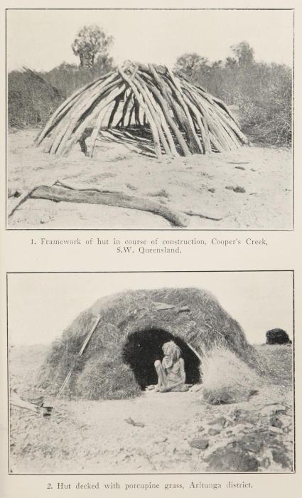
PLATE XV
1. Framework of hut in course of construction, Cooper’s Creek, S.W. Queensland.
2. Hut decked with porcupine grass, Arltunga district.
The men spend hours at a time in camp making or sharpening spears. When, moreover, the weapons are not in use, the hunters are most punctilious in preserving them from harm. The rule of the camp is never to lay a spear upon the ground for any length of time for two reasons; firstly, to prevent it from warping, and secondly, to eliminate the risk of breakage by somebody carelessly walking on to it. For these reasons the men, when camped, always take the precaution to stand their spears in a more or less upright position against the entrance of their huts, or against any bush or tree which happens to be growing close at hand.
Whenever possible, the opportunity of a sojourn in camp is seized for conducting a festive dance and song. For this purpose headgears and other decorations have to be manufactured, plumes and permanent ornaments renovated, and pigments prepared to adorn the persons taking part in the performance. Upon such occasions a native is never seen idle.
Quite apart from preparing himself in anticipation of an extraordinary event, however, a native might take advantage of a delay in camp to manufacture an article with which he can barter with an adjoining tribe. The most common article thus prepared is ochre. Many tribes do not possess a deposit of this natural pigment and they are most anxious to do business with their neighbours. In exchange for the ochre, they offer such things as weapons, pitjurileaf, fish, or yams. The ochre is carried to its destination either in lumps or prepared as a fine powder. In the former case it is packed in small fibre or fur-string bags; in the latter the powder is wrapped in thin sheets of bark and tied together with string into neat parcels. The preparation of the ochre-powder entails much grinding between the stone surfaces of a hand-mill. The ochre is used for decorating the body, as well as implements and weapons.
If now we enquire into the method of dress adopted by the aborigines of Australia, we find that most of the tribes originally walked about in the nude, and, apart from a few small personal decorations, possessed nothing in the shape of a covering which might be described as a dress. The advent of civilization has largely interfered with this ancient practice.
The now practically extinct south-eastern tribes, including those along the River Murray, used more of a body-covering than any others. Opossum, wallaby, and any suitable marsupial skins were collected and carefully sewn together, and with these rugs the natives could, if need be, cover the greater part of their bodies.
By far the most common mode is to tie a string around the waist, from which is suspended a tassel to cover the pubes. These tassels vary considerably in size according to the tribe which wears them. The smallest are found among the Wongapitcha in the Mann and Tomkinson Ranges; the appendage is there only worn by the men and is barely large enough to cover the part. It is made of human hair strands fastened at the knot of the tassel directly to the pubes; the covering is known as the “moiranje.” As a general rule, it might be said that the northern tribes have larger coverings than the central, although the Yantowannta and other Barcoo River tribes wear them as large as any. Even the Arunndta and Aluridja at special functions suspend large pubic tassels of fur-string from the waist-band.
The northern type of tassel consists of a great number of strings, usually of opossum fur, bound to a central piece, which is attached to the waist-band, either by two separate terminal strings, or by means of one single tie from the top of the tassel. The completed covering hangs from the waist like an apron. This type of pubic tassel is known to all north-central and northern tribes, and might be worn by either adult male or married female.
In place of the tassel a small sheet of the paper-bark is popular amongst the north coastal tribes. A narrow strip, from eight to twelve inches long, is folded transversely at its middle and hung over the waist-band, from which it pends like an apron as described of the tassel. Captain Matthew Flinders is perhaps the first European to have observed this custom, as far back as 1803, at Caledon Bay, where he observed a girl wearing “a small piece of bark, in guise of a fig leaf, which was the sole approximation to clothing seen.”
The women of Bathurst Island carry folded sheets of the paperbark or large food-carriers about with them, which, upon the
approach of strangers, they hold in front of their person.
Along the whole length of coast line of north Australia, the large shell of the pearl-oyster is made use of as a pubic covering. Even among such tribes as live remote from the sea, one may occasionally find the shell so used, in which case, of course, it has been acquired from a coastal tribe by barter. In order to hang the shell, two holes are drilled through it near the hinge line, at the top, and a string passed through them, with which it is tied to a belt. The rough exterior surface of the shell is ground smooth; and it is this side which lies against the body. The nacreous inner surface is frequently decorated with either painted designs or carvings subsequently tinted with ochre. The Sunday Island natives are especially adept at this type of decorative art, which will be referred to later.
Although the aboriginal does not wear much clothing, he is very particular about regularly anointing his supple skin. This precaution no doubt gives him greater protection against the changes of weather than all the modern ideas of clothing could do. What he principally applies is fat of emu and goanna, and on the north coast that of some of the larger fish as well. The emu in particular, and especially during a good season, accumulates masses of fat under its skin, which are readily removed, when slain by the hunter. This grease the native rubs over the whole surface of his body to shield the skin from the painful sting of the broiling sun and of the arid wind. In addition he covers certain parts of his body and face with red ochre and charcoal, both for cosmetic and protective purposes. The application of coloured pigments for purely decorative and ceremonial purposes will be discussed later
Hair-belts are worn by young and old, male and female. Children have only one or two twisted fur-strings tied around the waist. Among the coastal tribes of the Northern Territory, men wear belts made of twisted human hair. A skein of about thirty strings is tied at two points diametrically opposite, and, making these the ends, the sixty strings are loosely twisted into a hank about two feet in length. The belt thus completed is tied around the waist with a piece of human hair-string. The article is of practical use since it permits of
carrying various implements and weapons, which a man sticks between the belt and his body. A Wogait warrior was seen with a tomahawk thus placed at the back of his body; to stay the swinging of the handle he held it securely in the cleft between his buttocks. The same type of belt is used by the tribes of the Northern Kimberleys, and there they are always chosen when a man is wearing the pearl-shell appendage.
The Worora construct more elaborate articles by winding much human hair-string circumferentially (i.e. spirally) round a thick inner skein like the one described above. The finished belt looks like a cylindrical ring about an inch in thickness.
Other kinds of belts are made, but they are more for gala occasions, as when ceremonies are performed and tribal dances arranged.
When his affairs are working harmoniously, game secured, and water available, the aboriginal makes his life as easy as possible; and he might to the outsider even appear lazy. Blessed with a fair share of pristine philosophy by heredity, his motto might be interpreted in words to the effect that while there is plenty for to-day never care about to-morrow. On this account an aboriginal is inclined to make one feast of his supplies, in preference to a modest meal now and another by and by. The result is that, when a beast has been roasted, the whole of it is eaten, even though the participant family or group be small in comparison with the bulk of the spread. In consequence of this custom, the surfeiters find it necessary in times of plenty to frequently lie in camp, in undisguised idleness, until such time has lapsed as Nature must demand of their systems to overcome the discomforts which the reckless gorging had brought about. During this period of digestive recovery, an aboriginal endeavours to spend most of his time in sleeping off the objectionable after-effects of his temporary indiscretion. As an apology, however, one must admit that only too often the same individual is compelled to go for many days without even a mouthful to eat, and possibly, at the same time existing on a minimum of water, under the most trying conditions imaginable—conditions whose origin must be traced to the cycles of drought the great
southern continent is heir to, and which have become more drastic in their effects, since the coming of the white man, through the extermination of many indigenous animals and plants the original owners of the land used to depend upon for their existence.
It is during the leisure hours of any stay in camp that attention is paid to such operations as hair-cutting and beard-removing previously referred to. When the natives have been on the march for a time, and especially after they have been out hunting or collecting, numbers of thorns, prickles, and splinters are picked up by the soles of their feet, in spite of the thick horny nature of the skin. Many of these break off short and in due course set up irritation, necessitating their removal. Firstly the sufferer tries to remove the foreign body from the skin with his finger-nails; failing to succeed by this method, he cuts a small piece of wood the shape of an awl, and with its sharp point removes the obstacle. The prickle is often completely buried and quite invisible to the eye, yet it has to be removed. In order to locate it under those conditions, the aboriginal resorts to the method, not infrequently applied by the modern surgeon, of gently pressing the skin at different places with the tip of the instrument until the seat of pain has been located. At that spot he cuts away the skin to a depth sufficient to expose the hidden body, which he can then in most cases express with his fingers. During these operations the natives repeatedly give vent to a sharp, yet subdued “irr,” combining the expression of pain with that of disgust or temper.
The method adopted by the natives of walking one behind the other, where possible, is partly to minimize the risk of picking up prickles with their feet, and partly to obliterate the individual tracks of the party.
The dog is the aboriginal’s constant companion. In the original tribal areas the dingo, Australia’s wild dog, is captured and tamed young; in the more civilized districts the European dog has been acquired and bred by the natives in alarmingly large numbers. The animals are kept by both man and woman—in a single wurley one might count as many as fifteen dogs living with the human occupants. The yelping hordes are useless, except perhaps that they
raise the alarm when strangers approach the camp. Some of them are indeed dangerously vicious. The natives have the dogs about them merely for the love they bear towards them; it is on account of the unreasonable amount of petting and pampering, received at the hands of their masters, that the dogs become so thoroughly useless. A native just holds the unruly mob about him for company sake; he prefers to rely upon his own skill and instinct when hunting, and rarely allows his dogs to go with him; in fact, there seems little inclination on the part of the dogs to accompany the chase with their master They are so well looked after, and regularly steal so much from the general supplies of the camp, that they grow fat and lazy. When a dog seems to be off colour, or has been accidentally hurt, it is nursed like a sick child; it is placed by the fireside, upon the best rug available, and covered with other rags, the natives themselves going without any covering. One might occasionally find a gin going so far as to even suckle a pup at her breast.
Interesting discussions have taken place as to whether the dingo is indigenous to Australia or whether it has come hither from some other land, possibly with man. The wild dog found in the mountains of Java certainly resembles the dingo very closely. Whether or no, the dingo has existed in Australia quite as long as the primitive tribes. Osseous remains of the wild dog have been found contemporaneous with the extinct Diprotodon and other pre-historic monsters. Indeed in the “mammalian drifts” filling the ancient valleys of the ranges in the Noarlunga district, south of Adelaide, bones of such animals have been found showing distinctly the teeth-marks of the dingo upon them. In Victoria, and New South Wales also, dog remains have been found in old cave deposits in company with fossil-mammals and struthious birds, often buried beneath the basaltic flows and ashes of Mount Gambier and other volcanoes, which have long since become dormant. It seems most probable, therefore, that the dingo existed in Australia in the Pliocene period, or at any rate in that immediately following it. It is a strange circumstance that the dingo has never been traced to Tasmania, although, immediately opposite that island on the mainland, the dog was most plentiful in by-gone times. The surmise is that the animal had in its migration not reached so far south before Tasmania was
severed from the Australian continent by the breaking through of Bass Strait. It is reasonable to assume then that the dingo came to the south of Australia subsequent to the aboriginals who inhabited Tasmania.
CHAPTER XIV HUNTING
True sportsman’s instinct Comprehensive list of game Land-snails Freshwater mussels Marine molluscs Caterpillars Grubs Tree-climbing Trees felled by burning Witchedy hook Eggs of birds and reptiles Snakes and lizards Fishing methods described A turtle hunt Crocodile Dugong Hawk traps Wild geese and other birds The emu Big game hunted by men Opossums Burrowing marsupials Wallaby Kangarooing expeditions The buffalo Wild bee honey The honey ant
Nothing surpasses the pleasure of real pristine chase. The aboriginal’s ideal of life is attained when he finds himself in hot pursuit of the game, which shares with him the wilds of his ancient haunts. He lives at an accelerated pace; his pulse quickens, and in his excitement he completely dissociates his mind from everything but the spoor of his prospective prey. His vision is focussed rigidly upon the fleeing animal—he is blind so far as any other objects are concerned—and, behind it, he beholds just the one picture of his ambition realized, viz. the “kill.”
The love of the sport, the keenness of the senses, and the astounding powers of endurance are natural attributes, which the aboriginal alone knows how to use to their fullest. These are the hereditary gifts of man which characterize the primitive hunter; and these are the instincts which modern representatives of the human species have deplorably neglected.
The object of the chase is, of course, in its original phase, to find the means wherewith to sustain the hunter’s existence. Although he loves the sport so well, a native will never kill wantonly; whatever is slain is eaten; to kill just for the pleasure of the thing is beyond his comprehension and clashes seriously with his profound notions of justice and fair-play being meted out to all his fellow-creatures.
Apart from some of the flabby marine creations, there are few things in the animal world which the aboriginal does not eat, either raw or cooked in ashes. Generally speaking, the male only hunts the larger mammals and such things as require expert knowledge to locate, or the taking of which is associated with adventure and skill. We shall consider a few items separately.
The larger land-snails are collected by the women in their foodcarriers. After a good downpour of rain such come out from their hiding places in great numbers and can be collected in large numbers, but even in midsummer, in the ranges of central Australia, a meal of snails can at any time be secured by searching under tussocks and beneath stones. The principal species eaten by the Aluridja, Wongapitcha, and to a less extent by the Arunndta tribes, is the Helix perinflata. When sufficient have been collected, they are merely thrown upon hot ashes to roast and then picked out of the shell with a small pointed stick.
Fresh water mussels are gathered from the mud, roasted and consumed. These molluscs, known as the Unio, are very plentiful in some of the permanent water-holes, such as exist along the Cooper and Strzelecki Creeks in the Yantowannta, Wongkanguru, and Dieri country. Along the banks of the River Murray great heaps of the shells of such mussels are encountered by travellers even nowadays, indicating to what an enormous extent the molluscs were eaten by the extinct river tribes.
Countless marine species, both heliform gastropods like the periwinkle and cockle-like bivalves, contribute towards the daily meals of the coastal tribes. All along the south-eastern shores of South Australia, that is, upon the cliffs occurring between Kingston and the Glenelg River and in Victoria, many kitchen middens are still to be found containing heaps upon heaps of the large Turbo undulata—the remains of what the local tribes have feasted upon. Associated with these heaps are the stones of their ovens and other camp refuse.
The cliffs and reefs, which fringe the north coast of Australia, are profitable hunting grounds where all kinds of shell-fish, especially
oysters, abound. The last-named are gathered and thrown upon hot ashes; when the valves open, the “fish” are detached without any difficulty and swallowed.
The Wongapitcha and other desert tribes do not hesitate to consume quantities of green caterpillars, but such usually only at the beginning of a good season, when fresh herbs are available, and the morsel is in consequence claimed to have acquired a sweetish flavour. The only treatment the caterpillars receive is to be thrown upon hot ashes until they expand and straighten with the heat. The small hairs covering them are thus singed off, but the caterpillars are far from being cooked when eaten.
The most popular and at the same time most widely distributed article of diet in the insect line is the larva of the big Cossus moth, commonly known as the witchedy grub (Plate XVIII). The two varieties which make themselves most conspicuous are, firstly, one living in the roots of such shrubs as the Cassia and certain species of Acacia, and, secondly, one which bores into the butt of the eucalyptus. The first cannot usually be located by the eye, but its presence is determined by ramming the yam-stick into the ground under the root of the shrub and testing its resistance to leverage—if the grub is present, the root will readily snap, whereupon the native soon unearths it by digging with the stick and his hands. This variety is smaller than the tree-grub and is mostly of a yellow colour.
The abode of the tree-grub is detected by the native’s keen eye in the small holes the young larva bores into the bark and lives in until it attains the mature moth stage. The larva lives in the butt or in any of the larger limbs of the tree; consequently it may at times be concealed in the bark high above the ground. In the latter case the native will have to climb the butt and effect an ascent, no matter what the shape of the tree happens to be. Various methods are made use of, one of which we have already considered on page 13.
One of the commonest methods is to cut shallow notches in the bark of the butt, one above the other, and so placed that the toes of either foot of the climber can be placed into them, alternately right and left. The climber, as he ascends, cuts fresh notches into the bark
with his tomahawk; and if the butt is so big that he cannot hold on to it, he is obliged to cling to a notch with the fingers of one hand whilst the other hand is used to cut the new notch above it. In this manner he works his way upwards to the nearest lateral branch, whence the ascent is in most cases easier. It is wonderful with what assurance and ease the native accomplishes this dangerous task; and one marvels how it is possible for him to retain his balance against the vertical trunk of the tree. The notches, too, which he cuts into the bark, are so shallow that only the very toe-tips can be inserted. One uncertain movement, or one slip of either toe or finger, and he would fall to the ground; and considering the height to which he occasionally climbs, this might mean certain death. All grub-holes are examined on the way up and the occupants extracted. Vide Plate XIX, 1.
When the diameter of the butt is not too large to prevent the native from holding his hands around the distant side, the notches are dispensed with, and the climber simply “walks” up the tree, keeping his arms extended and allowing his hands to slide along the surface as he ascends. The method is in vogue principally in the tropical portions of Australia, where small-trunked trees and palms are plentiful in the jungles surrounding permanent water-holes and rivers.
In the same region, strong vines and creepers, which are interlaced with the branches of a tree to be explored, are climbed, hand over hand, by the hunter, who gets his hold by gripping the stem between the big and second toes.
In north-eastern Queensland, tree-climbing is accomplished by the aid of a long and strong piece of the lawyer-cane, which is passed around that side of the tree-trunk lying away from the climber. The native seizes both ends of this loop, one in either hand, and keeping it taut by throwing his body backwards into a sloping position, he places his feet against the tree. Momentarily relaxing the strain upon the cane, by a jerk from his arms, he thrusts the loop a short distance up the trunk, at the same time lifting one foot above the other as though he were walking up a ladder. The same operation is repeated, when the other foot is lifted; and thus he makes quick
progress towards the first lateral branches of the tree. Should at any time the climber want to use one of his hands, he passes one end of the cane under the knee of the same side as the hand to be liberated and holds the end between the big toe and that next to it.
Often the natives do not climb the tree, but prefer to light a fire at the base of it and wait until the flame has eaten its way through sufficiently far to fell it. After a giant of the woods has crashed to the ground, it is comparatively easy for the hunters to obtain any spoil concealed in its bark, hollows, or branches.
Although we have considered the methods of tree-climbing in connection with the witchedy grub, it must be understood that the same methods are employed in hunting small animals, in birdnesting, in honey-collecting, and so forth.
The witchedy grub is extracted from its hiding place by means of a light hooked stick. This implement is from four to six inches long and is usually cut from a small pronged twig, one arm of which is left the required length, the other cut short and sharpened to form the hook. The stick is inserted into the hole occupied by the witchedy grub, hook foremost, and pushed in until the grub is penetrated; then it is withdrawn, the hook bringing the grub with it. As the hole is usually small at its entrance, the bark is first cut away to a small depth with a tomahawk in order to avoid the constriction when the grub is being withdrawn. The witchedy-hook is known throughout central and southern Australia; the Arunndta word for it is “ullyinga.”
The witchedy grub is prepared like most things already described, namely, by throwing it upon hot ashes for a few moments until it straightens and expands, but does not burst. Although we Europeans have become adverse to eating anything in the grub line, there are many bush people who regularly partake of the witchedy; indeed, by many the grub is regarded as a very tasty dish. The flavour of the cooked witchedy is like that of scrambled egg, slightly sweetened.
The eggs and fledglings of all birds yield abundant food supplies during favourable seasons. In central Australia such seasons are dependent entirely upon the rains. Birds breed usually after the
setting in of rain, which might be once or twice a year, but in the driest regions, like the Victoria Desert, perhaps only once every few years. There is no doubt that emu, black swan, and native goose are amongst the biggest suppliers of eggs. Of the two last-named birds, in particular, enormous harvests of eggs are occasionally wrested during exceptional seasons. At these times the tribes who have been so bounteously favoured carry on a regular trade with neighbouring tribes, who have perhaps not had the same opportunity or good fortune.
The eggs of the larger birds mentioned are laid upon, or into, hot sand and frequently turned to ensure them cooking on all sides. The desert tribes of the Kimberley district have a knack of snatching the egg, as it lies upon the hot ashes, spinning it in the air, catching it again, and replacing it on to the ashes. The process might be repeated two or three times. The idea is to stir up the contents of the egg, in order that they may cook uniformly, much after the style of an omelette or scrambled egg.
The eggs of lizards, crocodiles, turtles, and other reptiles are also feasted upon. Of turtles in particular great numbers of eggs are collected along the north coast of Australia. The female turtle comes out of the ocean and lays many eggs in the sand, a short distance above high water mark; between fifty and sixty eggs are commonly found in a single nest. The turtle lays the eggs into a hole it previously scoops out, and covers them with sand it piles up with its paddles. The aboriginal locates the nest by tracking the characteristic spoor across the sand. When the nest has been discovered, the hunter probes the pile with a pointed stick or spear to ascertain whether the eggs are still available. This he can presage by looking at the point of the stick when he withdraws it: if the eggs are freshly laid, the point will be covered with yellow yolk, if partly hatched blood will show itself. The eggs are eaten in either condition. The lucky hunter, immediately he finds a nest, digs out the eggs with his hands and yam stick, and carries them in a food-vessel back to camp. Their preparation is much the same as that of birds’ eggs, but, in the case of the turtle’s, the white of the egg does not coagulate.
Snakes and lizards, especially the larger species, contribute towards the daily meals. They are tracked to their holes and hiding places and dug out. Great catches are made in the northern coastal districts by setting fire to areas covered with long, dry grass. The hunting party surrounds the burning patch and kills the reptiles, as they are driven out of their hiding places by the heat. Many creatures are overtaken by the flames and partially roasted before they can escape. These are collected as soon as the ground permits of walking over it, but very often such morsels fall into the claws of the birds of prey, which hover over the place directly the fires are started. In order to ensure a rapid spread of the flames, the natives make use of a stick, about a yard long, with a hook at one end. With this stick in their hand, they pick up some of the blazing grass at the hook-end, and run with it along and through the grass, setting fire to as much as they can, and in as short a time as possible.
Of the lizards, the most favoured are the species of Varanus, popularly known as the printhy and the goanna. These species live in central and northern Australia and attain a considerable size, the printhy in particular, living in the MacDonnell and Musgrave Ranges, attain a size of over six feet. These lizards in a good season are considered a delicacy, and the fat is prized as nutriment, as medicine, or as cosmetic ointment alike. The lizards are slain either in the caves they inhabit or as they are running from the hunter. In sandy stretches of country, the smaller goannas are often dug out of the holes they dwell in, and are killed on the spot.
Fishing is indulged in wherever the conditions permit of it. Opportunities are naturally rare in central Australia, and are restricted to only a few permanent water-holes along the courses of river systems like the Cooper, Diamentina, and Finke. In the northern rivers, which are nearly all permanently flowing, as for example the Fitzroy, Prince Regent, Victoria, Daly, Alligators, Roper, and Leichhardt, there is always an abundant supply of fish available. A common method practised both in central and northern Australia is to form a fishing party of men and boys, who enter a water-hole at one end and drive the fish before them, by making as much noise and splash as possible, at the same time gradually working their way
towards the shallow water Great care is taken not to allow any of the prey to make its escape by darting back through the line of the party into deep water again. Suddenly a final, united drive is made, through which most of the terrified fish find themselves in disastrously shallow water. In their frantic endeavour to escape, they entangle themselves in the mud, and can easily be grabbed by the members of the party. As fast as the fish are taken by the men, they are thrown on to the dry bank, where some gins are in readiness to seize them and dispatch them by crushing their heads between their teeth.
Many of the larger fish living in the water-holes have the habit of throwing themselves out of the water when the mud is stirred up in it; lying high and dry upon the muddy banks of the hole, they are easily seized by the natives and killed.
In the western rivers district of the Northern Territory, after the water has dried up in the creeks, leaving only shallow pools behind, the imprisoned fish are driven towards small inlets by means of long bundles of grass and twigs held horizontally in the water. In this way they are pushed forward on to the bank, and the water filters back to the hole. The fish are retained by the brushwood, from which they are easily extricated by the hunters.
The Carpentaria tribes build ingenious races at suitable sites, as for instance at a point where a river drains a billabong. By means of a series of embankments, the water is conducted along a number of constricted channels to long hollow logs, through which it flows, and, subsequently, empties itself over stacks of brushwood. The fish are entangled in the brushwood, whence they are removed by the hunters to a place of safety.
Crawfish are traced in shallow pools by keeping a constant lookout for the ends of their antennæ, which stick out above the surface of the turbid water; the native seizes these, and, with a jerk, hurls the crustaceans on to the bank.
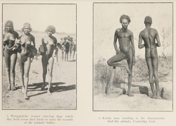
PLATE XVI
1. Wongapitcha women carrying dogs which they hold across their backs to enjoy the warmth of the animals’ bodies.
2. Kolaia man standing in the characteristic bird-like attitude, Cambridge Gulf.
In the Victoria River district of the Northern Territory, where there are suitable constrictions in shallow tidal-inlets and creeks, the natives sit in a line across the opening at ebb-tide after the following fashion: Each person squats with his legs doubled in the knees, the thighs resting well apart and in contact, one on either side, with those of his neighbours, who are seated just as he. When the last of the water ebbs out, the fish endeavour to make through the line of the fishers, but the moment one invades the angle contained by an aboriginal’s thighs, it is immediately pounced upon, caught, and thrown across to the women waiting on the shore.
In place of the human line, very often a net is spanned across an ebbing inlet, being kept in a more or less vertical position by a number of stakes, which are driven into the sand. These nets are made of vegetable fibre twine, strung or knitted together, after a loop-within-loop pattern, into pieces many yards in length.
Barriers are also built across shallow inlets, which upon the recession of the tide may occasionally retain large numbers of fish. Such structures are plentiful in the Berringin territory along the north coast, and in the Carpentaria Gulf country.
More temporary structures are made of branches and strips of paper-bark, stayed by vertical piles, driven into the sand at short distances apart. This type of barrier was seen mostly across the beds of creeks such as the McKinlay, Cullen, and Lennard.
A kind of noose is made by the Daly River tribes consisting of a long piece of big meshwork, which is loosely suspended across a narrow arm of water, or a creek, known to be frequented by larger varieties of fish. Whilst endeavouring to swim through the meshes of this contrivance, which at first offers no material resistance to the attempt, the fish, in carrying the noose onwards, forces its body partly through one of the meshes. Some of the prey might succeed in slipping through, others will pull the noose over their heads and fix the mesh in such a position that it will move neither forwards nor backwards. In this case, the fish will be obliged to linger until the natives come along to ascertain what luck they have had, when it is removed, together with any others which have met with a similar fate.
Practically all coastal tribes of Australia have made use of fishing nets at some time or other. Nowadays only the far northern coastal tribes still practise netting. The Daly River tribes, the Wogait, Sherait, Larrekiya, Berringin, and others construct nets after one and the same principle. Two hoops are made of the long shoots of Spinifex, growing upon the sandhills on the shore, usually by twisting two pairs of such pieces together, respectively, and tying their ends so as to form a complete ring, measuring about five feet in diameter. Round the inside of this ring is tied a circular net made out of fibre
twine or of Hybiscus bark. The net is made by hand, after the loopwithin-loop method previously referred to. To use the net, two natives, usually females, seize it with one hand placed at either side of the rim. As they wade out to a suitable depth, they hold the net between them, partly submerged and slightly inclined, so that the lower edge is in advance of the upper. In their free hands the gins carry branches, with which they frequently beat the water on either side, so as to drive any fish, within the beating radius, towards the centre of the net. So soon as a fish is noticed to go inside, the net is quickly turned up into a horizontal position and the captive bagged (Fig. 3).
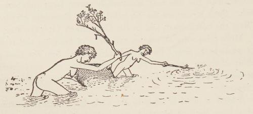
3. Berringin women netting fish.
A constant watch is kept for large fish, which may be swimming close in to shore, in order that they might be dispatched with a stone or throwing stick. Feeding stingrays are often captured this way When saw-fish come into shallow water, the natives wade in, seize the fish by their tails, and throw them up on to dry land before the dangerous “saws” can do any harm.
The spear is a favourite weapon with which to obtain a fish. A special type is used by the Larrekiya, Wogait, the Alligator River, and other coastal tribes in the north. The spear is about eleven feet long, has a shaft of reed or bamboo, and three barbed prongs of ironwood grouped in a circle around the head of the shaft. These spikes, measuring from twelve to fifteen inches, are attached with resin and string or paperbark. The barbs are short and directed backwards,
Fig.
each prong containing from eight to eleven, gradually increasing in size from the point towards the shaft. This trident-spear is used mostly for salt-water fish, and is thrown with or without a spearthrower. The idea of the three spikes is to jam the fish so that it is held by the retrorse barbs. The spearing is done either off reefs and rocks, or simply by wading out into shallow water and securing the prey as it emerges from sea-weed or swims near the sandy bottom; many of the coastal and river tribes do much of their spearing from the bow of a canoe. Some tribes make similar fish-spears, but with two prongs only
The Kimberley tribes of Western Australia, the island tribes off the north coast and the north Queensland coastal tribes use straight, pointed spears of mangrove wood, those of the Crocker Island being exceptionally well finished and of harder wood.
The tribes living more inland in the river districts of the north also use a singly pointed, straight fish-spear. A native does most of his fishing by perching himself upon a high bank, rock, or fallen log, at a place where he knows fish are being attracted to the surface of the water by flies or other causes. He stands rigidly for hours, with his spear poised, patiently waiting for the opportunity, which will allow him to thrust the sharp point into the body of the unsuspecting prey. The spear is thrown with such force that it either sticks in the mud below or disappears under water for a while. In either case, the native has to wade or swim out to the missile, and when he retakes it, the fish, if he has been successful, is found sticking to the end of the spear.
The hook and line are used by the Daly and Alligator River tribes of the Northern Territory. Two types of hook are employed. One is cut out of a pelvic bone or shoulder blade of the kangaroo, or out of the pearl shell. It is of a strongly bent sickle-shape, pointed at one end and containing a notch at the other, to which a line can be securely tied.
The other hook consists of two pieces of bone of unequal length. The shorter and thinner piece, about two inches in length, is pointed at one end and tied at an angle to the bigger piece, which is about