6 minute read
Technical
Low pressure and under-sized pipework
Low gas pressure at gas appliances due to undersized pipework is the topic of many contacts to Gas Safe Register, both from registered businesses and members of the public. Here, Technical Officer Gary Aymes looks at some of the causes and what steps to take.
Advertisement
Pressure loss is an inevitable occurrence when designing an installation and needs to be considered. Pressure is lost because of the frictional resistance of the components used in the installation pipework that are exposed to gas. The amount and size of pipework and fittings used in the installation all contribute to a certain amount of drop in pressure across the system.
When designing an installation, the size of installation pipework required should be determined from the maximum gas rate of the appliance(s) to be connected, and an allowance may need to be considered for any future developments or extensions in the property.
To meet requirements and minimise pressure loss, an understanding of what can affect this can help gas engineers when they are designing the system. This includes the gas consumption of the appliance(s), the length of pipework required, the number and type of fittings, and the type and bore of pipework.
All these factors increase the frictional resistance to the flow of gas, which, in turn, increases the pressure loss.
BS 68911 states that, for natural gas installations, the design pressure loss between the outlet of the primary meter installation and the point to be connected to any appliance inlet shall not exceed 1mbar at the design installation maximum flow rate: for LPG installations this figure is 2mbar.
How to calculate gas pipework size in a domestic property
When you’re quoting for a new gas boiler, you must survey the property before you start work to decide the most suitable boiler position, taking into account the layout of the property and your customer’s needs. With the position of the boiler established, you must work out the route that the gas pipework will take from the meter to the appliance position.
Once the route has been decided, you must calculate the pipe sizing to serve the gas
appliance with an adequate supply of gas. To do this calculation, you need to carry out a pipe-sizing exercise using either the tables provided in BS 6891, or appropriate training materials.
First, measure the route of the pipework, allowing the appropriate additional lengths for fittings. This will give you what is called the ‘equivalent length’. This is the total length of pipe that you should use in your final calculation.
Once you have your equivalent length, use Table A.1 from BS 6981 (or equivalent) to work out the required pipe diameter. To do this, you need either the heat input or gas rate of the appliance(s) in the property. If the total heat input is not listed, use the nearest measurement above what is needed. You should then follow the table across, where the pressure loss per metre for each pipe size is listed.
By multiplying this number by the equivalent length, you can see which pipe size will ensure that there is no more than a 1mbar drop in pressure across the pipework installation.
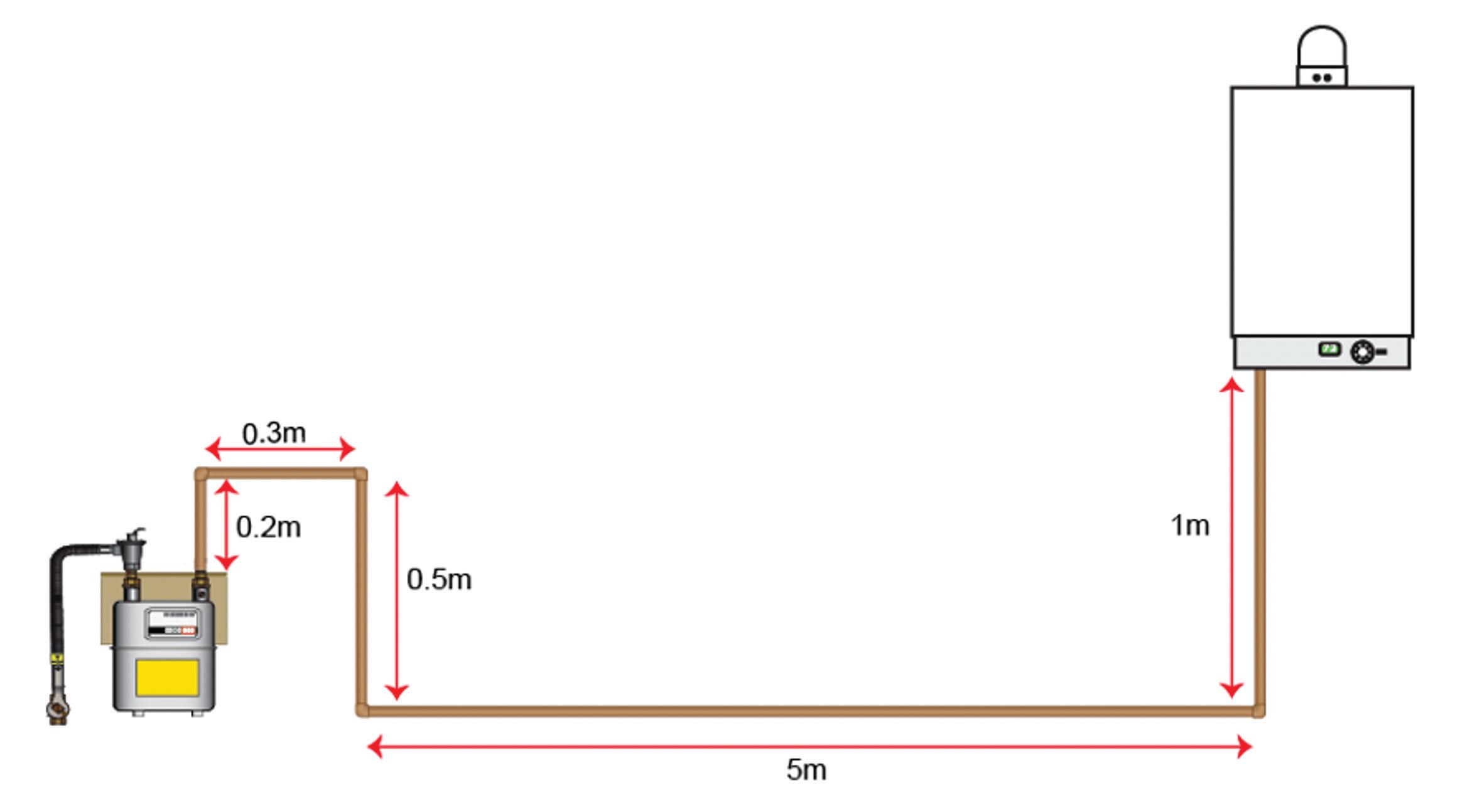
The example shown opposite is an installation with a gas meter and a single appliance and the figures used in the calculation are taken from Tables A.1 & A.5 of BS 6891. The appliance is a boiler of 29kW net.
If there is a cause for concern Existing installations
If you find potential problems with pipework or pressure issues, then further investigation is required. It could be that the pipework has been sized correctly but there is now a blockage, or there may be upstream network issues affecting the supply pressure to the property.
In this instance, contact the manufacturer of the appliance(s) affected for guidance of the safe levels to which their appliance will work. Using this, your engineering judgement and guidance from the Gas Industry Unsafe Situation Procedure2 , you must assess whether the readings are affecting the safe operation of the appliance.
Why can’t the design pressure loss exceed 1mbar?
As an example, the gas engineer installs an appliance on existing pipework but does not ensure that the pipework has a maximum 1mbar pressure loss, in accordance with BS 6891. This installation pipework is losing 5mbar, with the working pressure at the meter outlet at 20mbar, and therefore the appliance would seem to be receiving 15mbar, which is within the manufacturer’s specifications.
The engineer assumes that because the manufacturer’s instructions state that the appliance will work safely with a minimum of 14mbar, then this is acceptable. However, the pressure in the network at peak demand reduces to 20mbar and the meter absorbs 4mbar, leaving 16mbar at the meter outlet. The 5mbar loss across the pipework now leaves only 11mbar at the appliance – below the manufacturer’s minimum. This means the appliance may not work in accordance with the manufacturer’s instructions. The engineer in attendance must risk assess the installation and follow IGEM/G/11, the Gas Industry Unsafe Situations Procedure, if the appliance is working unsafely. ■
Bibliography
1 BS 6891: 2015 – Specification for the installation and maintenance of low-pressure gas installation pipework up to 35mm (R1 ¼) on premises 2 Gas Industry Unsafe Situation Procedure (IGEM/G/11 Edition 2)
Example of a 29kW boiler single-appliance installation
Exerpt from BS 6891 Table A.1, showing the pressure drop in mbar per metre of pipework. The arrow shows the correct pipe size for this installation (calculation below)
Flow Rate Heat input (gross) Heat input (net) 8mm 10mm 12mm 15mm 22mm 28mm 35mm
2.50 27.01 24.56 - - - 0.3353 0.0565 0.0156 0.0049 2.75 29.72 27.01 - - - 0.3945 0.0663 0.0183 0.0058 3.00 32.42 29.47 - - - 0.4577 0.0769 0.0212 0.0067
Exerpt from BS 6891 Table A.5, showing the additional lengths to be added per fitting
Ç
Pipe size 45° bend 90° bend 90° elbow Tee (flow entering the tee from branch) Tee (flow exiting the tee into branch)
15mm 0.15m 0.20m 0.40m 0.75m
22mm 0.20m 0.30m 0.60m 1.20m 1.20m 1.80m
(1) Using Table A.1 from BS 6891, read across from equivalent heat input the section of pipework is feeding (or next figure up if yours is not listed). If you look at 15mm pipe in the 29.47 kW Net column (the correct column for this installation), you can see that you get a loss of nearly 0.5mbar per metre, and if you go to 28mm pipe then you could run nearly 50 metres of pipe. Therefore, 22m pipework is most appropriate, giving you a drop per metre of 0.0769 mbar. (2) Using Table A.5 from BS 6891 work out equivalent pipe length, which is the pipe length plus an additional allowance for the fittings
used. In this installation there are 4 elbows (7m of pipe + 2.4m for fittings (4 x 22mm 90 elbows) = 9.4m). Therefore, the equivalent length of this installation is 9.4m. (3) Multiply the equivalent pipe length (9.4m) with the pressure drop per metre of the appropriate pipe size (0.0769 mbar), which gives you the pressure loss across the installation. The pressure loss across the system using 22mm pipework will be 0.72286 mbar (9.4m equivalent length x 0.0769 mbar drop per metre).
Total pressure loss calculation. The end result should be less than 1mbar
Heat input Total equivalent pipe length Estimated pipe size Pressure loss per m Total pressure loss across pipework
29kW net 9.4m 22mm 0.0769 mbar 0.73 mbar


