QUICK LED 23
PROFILED
PROFILED H9
PROFILED MACRO
PROFILED MICRO
PROFILED TONDO
PROFILED 230
SCHOOL
SCHOOL UV-C
SHOW
SLIM
STRIP LED
THE PANEL 2
THE PANEL 2 MICROPRISMATICO
THE PANEL BIEMISSIONE
THE PANEL IP65
YALE
076 073 047 083 025 088 063 051 059 058 057 056 054 055 053 060 027 033 071 045 080 011 011 021 023 039 ALL-TRACK INCASSO ALL-TRACK PLAFONE-SOSPENSIONE CREP DRIVERS new FRAME PANEL GESTIONE LUCE LI-NEAR LUNA GIADA SYSTEM DALI+EME MODULE TRACK MODULE SENSOR MODULE L,T JOINTS new new STRIP LED 230V new DALI new newnew DRIVERS 24-48V PER STRIP LED newnew INTERFACCE 24-48V PER STRIP LED Nuovo prodotto New product Upgrade prodotto Product upgrade
ANGOLARE
INCASSO H12
PROFILED
PROFILED
H16
1
Per celebrare i suoi 75 anni, Novalux ha in serbo progetti speciali e tantissime novità che ci accompagneranno durante il 2023
To celebrate its 75th anniversary, Novalux has special projects and lots of new things in store that will accompany us through 2023

STAY TUNED!

Anniversary 2
3
THE PANEL 2 11 THE PANEL 2 MICROPRISMATICO 11
THE PANEL BIEMISSIONE 21
THE PANEL IP65 23
FRAME PANEL FRAME PANEL TL 25
SCHOOL 27 SCHOOL UV-C 33 YALE 39
SLIM 45 CREP 47
PROFILED TONDO 53
new PROFILED 230 60
LED PANEL CEILING / WALL / FLOOR LI-NEAR 63
new new new new
SHOW 71 ALL-TRACK INCASSO 76
PROFILED MACRO 54
PROFILED MICRO 55
PROFILED H9 56
PROFILED H16 57
PROFILED INCASSO H12 58
PROFILED AD ANGOLO H16 59 ALL-TRACK PLAFONE SOSPENSIONE 73
new 19 13 L DOWNLIGHT TRACK STRIP LED 80 GESTIONE LUCE LIGHT MANAGEMENT 88 DRIVERS 83
STRIP LED AND LIGHT MANAGEMENT LUNA 51


INCASSO IN CARTONGESSO RECESSED INTO PLASTERBOARD SOSPENSIONE SUSPENDED THE PANEL BIEMISSIONE 21 SLIM 45 FRAME PANEL FRAME PANEL TL 25 BINARIO TRACK MOUNTED VELETTA LIGHT COVE CREP 47 LI-NEAR 63 THE PANEL IP65 23 SCHOOL 27 SCHOOL 27 PROFILED H16 57 PROFILED AD ANGOLO H16 59 PROFILED MICRO 55 THE PANEL 2 11 THE PANEL 2 11 THE PANEL 2 MICROPRISMATICO 11 THE PANEL 2 MICROPRISMATICO 11 THE PANEL 2 11 THE PANEL 2 MICROPRISMATICO 11 PROFILED TONDO 53 PROFILED H9 56 PROFILED INCASSO H12 58 SCHOOL UV-C 33 SCHOOL UV-C 33 PROFILED MACRO 54 YALE 39 ALL-TRACK PLAFONE SOSPENSIONE 73 SHOW 71 ALL-TRACK INCASSO 76 new 4

THE PANEL IP65 23
LUNA 51 PARETE WALL MOUNTED LUNA 51 CREP 47 CREP 47 LI-NEAR 63 SCHOOL 27 THE PANEL 2 11 THE PANEL 2 MICROPRISMATICO 11 PROFILED H16 57 PROFILED TONDO 53 PROFILED H9 56 PROFILED MICRO 55 PROFILED MACRO 54 YALE 39 new new 19 13 L PROFILED 230 60 new new STRIP LED E GESTIONE LUCE STRIP LED AND LIGHT MANAGEMENT new STRIP LED 80 new DRIVERS 83 new GESTIONE LUCE LIGHT MANAGEMENT 88 5
PLAFONE CEILING MOUNTED
LEGENDA SIMBOLI SYMBOLS LEGEND
Incasso a soffitto in muratura, Luce diretta
Recessed into brick/concrete ceiling
Direct light
Incasso a parete in muratura, Luce diretta
Recessed into brick/concrete wall
Direct light
Incasso a parete in muratura, Luce indiretta asimmetrica verso il basso Recessed into brick/concrete wall
Asymmetric indirect light, downward
Incasso a soffitto in cartongesso o in appoggio su pannelli, luce diretta
Recessed into plasterboard false ceiling or supported by panels, direct light
Incasso a parete in cartongesso, Luce diretta
Recessed into plasterboard wall
Direct light
Incasso a parete in cartongesso, Luce indiretta asimmetrica verso il basso Recessed into plasterboard wall, Asymmetric indirect light, downward
Incasso a soffitto in cartongesso, Luce spot orientabile
Recessed into plasterboard false ceiling Adjustable spot light
Installazione su veletta, Luce spot orientabile
Installed on pelmet Adjustable spot light
Installazione su veletta, Luce indiretta
Installed on pelmet Indirect light
Binario, luce diretta Track mounted direct light


Binario, Luce diretta orientabile Track mounted adjustable Direct light
Proiettore a binario, Luce diretta orientabile Track mounted projector Adjustable direct light
Lampada da terra Floor lamp
Picchetto, Luce orientabile
Stake mounted adjustable light
Plafone, luce diretta
Ceiling mounted direct light
Plafone, luce diffusa
Ceiling mounted, diffused emission
Parete, luce diretta
Wall mounted direct light
Parete, luce diffusa
Wall mounted, diffused emission
Incasso a terra Floor recessed
Parete, Luce indiretta asimmetrica verso il basso Wall mounted, Asymmetric indirect light, downward
Parete, Luce diretta radente
Wall mounted grazing Direct light
Parete, Luce indiretta radente
Wall mounted grazing Indirect light
CRI >90
UGR <19


GRUPPO 0
RISCHIO FOTOBIOLOGICO
GRUPPO 1
RISCHIO FOTOBIOLOGICO
Indice di resa cromatica >90
Colour rendering index >90
Apparecchio UGR <19
Fixture with UGR <19
Rischio fotobiologico esente Photobiological risk exent
Rischio fotobiologico 1 Photobiological risk 1
Apparecchio provvisto di caricabatterie a muro con spina europea Fixture equipped with wall charger with European plug
Parete, Luce mista radente Wall mounted grazing Direct/indirect light Sospensione, luce diffusa Suspended diffused light
Sospensione, luce diretta Suspended direct light


Sospensione, luce mista Suspended direct/indirect light
Sospensione, luce indiretta Suspended indirect light


Bollard Bollard
Garanzia
C.A.M. Edilizia
Conforme al DM


23 giugno 2022 n. 256
C.A.M. Edilizia
Compliant with decree
23 june 2022 n. 256
C.A.M. Edilizia
Warranty
novità New lighting fixture Prodotto in Italia Made in Italy Progettato in Italia Designed in Italy MADE IN ITALY DESIGNED IN ITALY NEW
Prodotto
6
Classe I Class I
Classe III Class III
Alimentato in corrente alternata
220-240V 50/60hz
In alternating current
220-240V 50/60hz
Alimentato a tensione di rete
Mains voltage
Alimentato in tensione costante
24Vdc
In constant voltage 24Vdc
Valore di alimentazione in corrente costante
Constant current value
Cablaggio con alimentatore elettronico dimmerabile analogico, regolazione mediante potenziometro con segnale 0-10V Analogic dimmable wiring, regulation by potentiometer 0-10V
Cablaggio con alimentatore elettronico dimmerabile analogico, regolazione mediante potenziometro con segnale 1-10v Analogic dimmable wiring, regulation by potentiometer 1-10v
Cablaggio con alimentatore elettronico dimmerabile digitale con interfaccia DALI Dimmable wiring by DALI interface
Cablaggio con alimentatore elettronico dimmerabile, regolazione tramite pulsante Dimmable wiring regulation by traditional switch-dim
Cablaggio con alimentatore elettronico dimmerabile, regolazione con dimmer a taglio di fase TRIAC Dimmable wiring, regulation with phase-cutting dimmer TRIAC
Dimmer integrato Built-in dimming device
Grado di protezione IK: resistenza dell’involucro dell’apparecchio agli impatti meccanici esterni
IK index of protection:
resistance of fixture casings against external mechanical impacts
Grado di protezione IP: efficacia di tenuta di contenitori degli apparecchi contro l’intrusione nel dispositivo di corpi estranei di tipo solido e liquido
IP index of protection:
effective seal for containers of electrical equipment against intrusion of liquids and solids
Minimo livello di oscillazione della luce, minor affaticamento visivo e migliore efficienza di sistema
Minimum level of light oscillation, less visual fatigue and better system efficiency
.01 BIANCO WHITE .00 TRASPARENTE TRANSPARENT .02 NE NERO BLACK .96 ANODIZZATO NATURALE ANODIZED NATURAL FINISH .99 NON DEFINITO UNDEFINED .94 GRIGIO ANTRACITE ANTHRACITE GREY FINITURE
FLICKER FREE
FINISH
Classe II Class II
220-240V 50/60Hz 350 mA 24Vdc 1-10V 0-10V PUSH L,C DIMMABLE IP 20 IK 10 7
8
LED PANEL
9
10
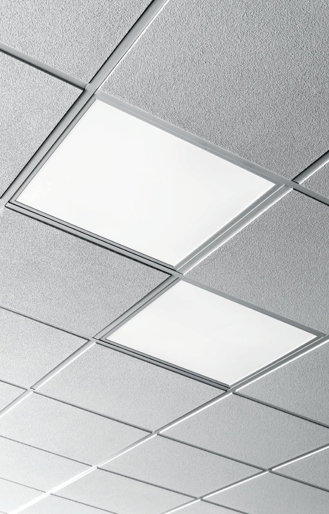
THE PANEL 2
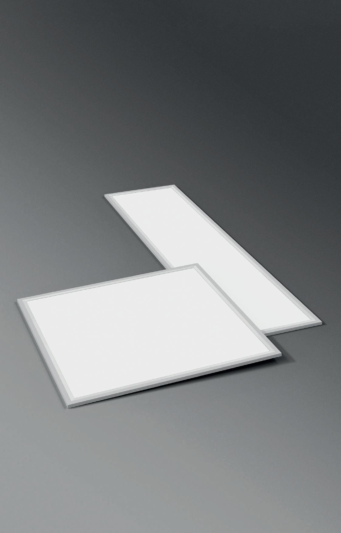
Pannello LED con cornice in lega di alluminio verniciata a polvere di colore bianco, diffusore opale in PMMA resistente ai raggi UV.
UGR<19 4H-8H, S=0,25, indice di riflessione 70-50-20. Installabile ad incasso su controsoffitto a pannelli con struttura a vista senza accessori, per le altre installazioni prevedere gli opportuni accessori da ordinare a parte. Alimentatore elettronico incluso.
LED panel with frame made of white powder coated aluminium alloy, opal diffuser in PMMA, UV resistant. UGR<19 4H-8H, S=0,25, reflexion index 70-50-20. No accessories needed for installation on exposed grid ceiling, accessories for other installations to be ordered separately. Integrated electronic driver.
Per sopperire alle attuali problematiche di reperibilità dei componenti elettronici, disponiamo di articoli alternativi (non combinabili) di pari caratteristiche tecniche. In order to meet the current problems of availability of electronic components, we have alternative items (not combinable) of the same technical features.
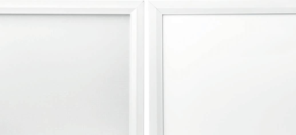
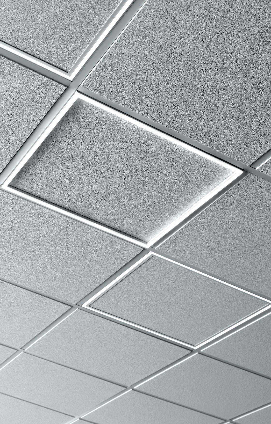
THE PANEL 2
Pannello LED con cornice in lega di alluminio verniciata a polvere di colore bianco, diffusore microprismatico UGR<19 in PMMA resistente ai raggi UV. Installabile ad incasso su controsoffitto a pannelli con struttura a vista senza accessori, per le altre installazioni prevedere gli opportuni accessori da ordinare a parte. Alimentatore elettronico incluso.
LED panel with frame made of white powder coated aluminium alloy, micro-prismatic diffuser UGR<19 in PMMA, UV resistant No accessories needed for installation on exposed grid ceiling, accessories for other installations to be ordered separately. Integrated electronic driver.
Per sopperire alle attuali problematiche di reperibilità dei componenti elettronici, disponiamo di articoli alternativi (non combinabili) di pari caratteristiche tecniche. In order to meet the current problems of availability of electronic components, we have alternative items (not combinable) of the same technical features.
1195 295 8 1195 295 8 595 595 8 595 595 8 C.A.M.
POWER FLUX 3000K FLUX 4000K 35W 3343 lm 102001.01 3447 lm 102002.01 DALI-PUSH POWER FLUX 3000K FLUX 4000K 35W 3343 lm 102096.01 102070.01 3447 lm 102097.01 102071.01 POWER FLUX 3000K FLUX 4000K 32W 3386 lm 102062.01 3490 lm 102063.01 DALI-PUSH POWER FLUX 3000K FLUX 4000K 32W 3386 lm 1020A0.01 102074.01 3490 lm 1020A1.01 102075.01 POWER FLUX 3000K FLUX 4000K 35W 3343 lm 102007.01 3447 lm 102008.01 DALI-PUSH POWER FLUX 3000K FLUX 4000K 35W 3343 lm 102098.01 102072.01 3447 lm 102099.01 102073.01 POWER FLUX 3000K FLUX 4000K 32W 3386 lm 102066.01 3490 lm 102067.01 DALI-PUSH POWER FLUX 3000K FLUX 4000K 32W 3386 lm 1020A2.01 102076.01 3490 lm 1020A3.01 102077.01
Edilizia
UGR <19 CRI >90 FLICKER FREE FLICKER FREE 220-240V 50/60Hz PUSH IP 40 THE PANEL 2 600x600 THE PANEL 2 MICROPRISMATICO 600x600 THE PANEL 2 1200x300 THE PANEL 2 MICROPRISMATICO 1200x300 * * Solo versione DALI-PUSH / Only DALI-PUSH version * Solo versione DALI-PUSH / Only DALI-PUSH version UGR <19 220-240V 50/60Hz PUSH IP 40 * * RISCHIO FOTOBIOLOGICO GRUPPO 0 DESIGNED IN ITALY RISCHIO GRUPPO 0 DESIGNED IN ITALY C.A.M. Edilizia
MICROPRISMATICO
11 LED PANEL THE PANEL 2
THE
PANEL
2
ACCESSORI PER INSTALLAZIONE AD INCASSO ACCESSORIES FOR RECESSED MOUNTING
KIT MOLLE PER INSTALLAZIONE AD INCASSO
Per versioni 600x600 e 1200x300, per installazione in battuta in cartongesso di spessore 10-12,5 mm.
SPRINGS KIT FOR RECESSED
INSTALLATION
For 600x600 and 1200x300 versions, for installation by frame contrasting in plasterboard of thickness 10-12,5 mm.
1 Avvitare le molle al dado scorrevole inserito nella cornice.
Screw the springs to the nut inserted in the frame.
2 Senza eccedere le dimensioni della cornice del The Panel, praticare una riduzione di spessore del cartongesso per alloggiare le viti e la staffa, al fine di arrivare completamente a battuta sul controsoffitto.
Without exceeding the frame size of The Panel, reduce the thickness of the plasterboard to house the screws and the bracket, in order to completely recess them in false-ceiling.
KIT PER INSTALLAZIONE AD INCASSO A RASAMENTO
Profilo da rasare su cartongesso di spessore 12,5 mm.
Il pannello si installa in appoggio
KIT FOR LEVELLED RECESSED INSTALLATION
Profile to be levelled on 12,5 mm thick plasterboard.
Prevedere una zona libera per il profilo di almeno 40 mm di distanza dal taglio. Reserve a free space for the profile of at least 40 mm away from the cut.
KIT ANTICADUTA
Cavo in acciaio da fissare a soffitto o strutture tramite morsetto in ottone nichelato e aggancio a vite sul pannello.
ANTI FALL-OUT KIT
Steel cable to be fixed to the ceiling or structures using a nickel-plated brass clamp and screwed on the panel.
Per accessori di installazione su controsoffitti a struttura nascosta, contattare l’ufficio tecnico Novalux. For installation accessories on concealed grid ceilings, please contact Novalux technical office.
4x 25 10 ÷ 12,5
CODE VERSION 102028.99 600x600 102029.99 1200x300 CODE L (mm) 102031.99 3000 CODE 16215.99
12,5 H 100 L 640 W 640 12,5 H 100 L 1240 W 340 45° 45° H 50 L 575 W 575 H 50 L 1175 W 275
12 LED PANEL
THE PANEL 2 ACCESSORI PER INSTALLAZIONE A PLAFONE ACCESSORIES FOR CEILING MOUNTING
KIT PER INSTALLAZIONE A PLAFONE
Per versioni 600x600 e 1200x300, non installabile a parete o in fila continua. Distanza tra prodotto e soffitto 40 mm.
KIT FOR CEILING MOUNTING
For 600x600 and 1200x300 versions, not suitable for wall surface or contiunuous line installation. Distance between the fixture an the ceiling 40 mm.
CODE 16213.99
1 Installare la staffa centrale. Install the center bracket.
2 Fissare le staffe di ancoraggio al pannello. Fix the anchoring brackets to the panel.
3 Installare dal basso, lateralmente, seguendo la direzione della freccia. Scorrere fino allo scatto della molla. Install from the bottom, follow the arrow’s direction. Slide to engage the spring.
BOX PER INSTALLAZIONE A PLAFONE
Kit da assemblare, non installabile a parete. Idoneo per l’alloggiamento del kit di emergenza (1020A4.99/1020A5.99).
KIT FOR CEILING MOUNTING
To be assembled, not suitable for wall surface mounting. Suitable for emergency kit (1020A4.99/1020A5.99).
595 115
300 43 1200 600 43 600
CODE VERSION 102086.01 600x600 102087.01 1200x300 13 LED PANEL THE PANEL 2
THE PANEL 2 COMPOSIZIONI SOSPESE SUSPENDED COMPOSITIONS
16223.99 Kit sospensioni Kit suspensions
16227.96
Kit giunti + sospensioni Kit joints + suspensions
16232.96 Kit giunti (privi di sospensioni) Kit joints (without suspensions)
16228.01 Kit snodo + sospensioni Kit hinge + suspensions
16231.96
Kit giunti + sospensioni + staffe inclinate Kit joints + suspensions + Inclined brackets
16230.99
Kit sospensioni inclinate Kit inclined suspensions
16223.99 Kit sospensioni Kit suspensions
16232.96
Kit giunti (privi di sospensioni) Kit joints (without suspensions)
16227.96 Kit giunti + sospensioni Kit joints + suspensions
16234.01 Kit snodo (privo di sospensioni) Kit hinge (without suspensions)
16230.99
Kit sospensioni inclinate Kit inclined suspensions
14 LED PANEL
THE PANEL 2
ACCESSORI PER INSTALLAZIONE A SOSPENSIONE ACCESSORIES FOR SUSPENSION MOUNTING
KIT DI ALIMENTAZIONE PER SOSPENSIONE Cavo di alimentazione trasparente
KIT n.4 SOSPENSIONI per versioni 600x600 e 1200x300.
KIT nos.4 SUSPENSIONS for 600x600 and 1200x300 versions.
Avvitare i regolatori millimetrici ai dadi scorrevoli inseriti nella cornice.
Screw the joints to the nuts inserted in the frame.
KIT n.2 GIUNTI + SOSPENSIONI per versioni 600x600 e 1200x300.
KIT nos.2 JOINTS + SUSPENSIONS for 600x600 and 1200x300 versions.
Avvitare i giunti ai dadi scorrevoli inseriti nella cornice.
Screw the joints to the nuts inserted in the frame.
L 2x 84 54 50
POWER SUPPLY KIT FOR SUSPENSION Transparent power cable CODE L (mm) Cavo / Cable (mm2) 108919.01 1200 3x1,5 108920.01 3000 3x1,5 108921.01 1200 5x1,5 108922.01 3000 5x1,5 CODE L (mm) 16223.99 3000 CODE L (mm) 16227.96 3000 15 LED PANEL THE PANEL 2
THE PANEL 2
ACCESSORI PER INSTALLAZIONE A SOSPENSIONE ACCESSORIES FOR SUSPENSION MOUNTING
KIT n.2 GIUNTI (privi di sospensioni) per versioni 600x600 e 1200x300.
KIT nos.2 JOINTS (without suspensions) for 600x600 and 1200x300 versions.
CODE 16232.96
Avvitare i giunti ai dadi scorrevoli inseriti nella cornice.
Screw the joints to the nuts inserted in the frame.
KIT n.4 SOSPENSIONI INCLINATE per versioni 600x600 e 1200x300
KIT nos.4 INCLINED SUSPENSIONS for 600x600 and 1200x300 versions
CODE L (mm) 16230.99 3000
Avvitare le sospensioni ai dadi scorrevoli inseriti nella cornice.
Screw the suspensions to the nuts inserted in the frame.
KIT n.2 GIUNTI + SOSPENSIONI + STAFFE INCLINATE per versione 600x600.
KIT nos.2 JOINTS + SUSPENSIONS + INCLINED BRACKETS for 600x600 version.
CODE L (mm) 16231.96 3000
Avvitare i giunti ai dadi scorrevoli inseriti nella cornice.
Screw the joints to the nuts inserted in the frame.
2x 4x 2x
16 LED PANEL
THE PANEL 2 ACCESSORI PER INSTALLAZIONE A SOSPENSIONE ACCESSORIES FOR SUSPENSION MOUNTING
KIT SNODO + n.2 SOSPENSIONI per versione 600x600 profilo in lega di alluminio verniciato.
KIT HINGE + nos.2 SUSPENSIONS for 600x600 version profile in powder coated aluminium alloy.
Avvitare lo snodo ai dadi scorrevoli inseriti nella cornice.
Screw the hinge to the nuts inserted in the frame.
KIT SNODO (privo di sospensioni) per versione 1200x300 profilo in lega di alluminio verniciato.
KIT HINGE (without suspensions) for 1200x300 version profile in powder coated aluminium alloy.
Avvitare lo snodo ai dadi scorrevoli inseriti nella cornice.
Screw the articulated hinge to the nuts inserted in the frame.
THE PANEL 2 MICROPRISMATICO THE PANEL 2
CODE L (mm) 16228.01 3000 CODE 16234.01 17 LED PANEL THE PANEL 2
THE PANEL 2
ACCESSORI PER INSTALLAZIONE A BINARIO ACCESSORIES FOR TRACK MOUNTING
KIT BINARIO 600x600 completo di 2 adattatori (elettrico/meccanico) per binario elettrificato All-Track.
KIT FOR TRACK MOUNTING 600x600 supplied with 2 adaptors (electrical/mechanical) for electrified All-Track.
THE PANEL 2
KIT BINARIO 1200x300 completo di 2 adattatori (elettrico/meccanico) per binario elettrificato All-Track.
KIT FOR TRACK MOUNTING 1200x300 supplied with 2 adaptors (electrical/mechanical) for electrified All-Track.
ACCESSORI EMERGENZA ACCESSORIES EMERGENCY
KIT DI ALIMENTAZIONE IN EMERGENZA
Per versioni 600x600 e 1200x300, per installazione ad incasso o a plafone con Box (102086.01, 102087.01).
Completo di connettori polarizzati per il collegamento dell’alimentatore.
KIT FOR EMERGENCY For 600x600 and 1200x300 versions, for recessed installation or ceiling installation with Box (102086.01, 102087.01) Polarized connectors included.
1192 85 80 592 85 80
CODE VERSION TRACK 102055.01 3P+DALI All-Track / Novatrack / Dim-Track 102053.01 3P All-Track / Novatrack CODE VERSION TRACK 102056.01 3P+DALI All-Track / Novatrack / Dim-Track 102054.01 3P All-Track / Novatrack IP 20
CODE TIME CHARGE A (mm) D (mm) H (mm) L (mm) 1020A4.99 1h 12h 38 44 25 164 1020A5.99 3h 12h 38 44 25 164 Flusso in emergenza - Emergency flux 1h 3h THE PANEL 2 35W 12% 5% THE PANEL 2 MICROPRISMATICO 35W 12% 5% A H L D 18 LED PANEL
19 THE PANEL 2 LED PANEL
20
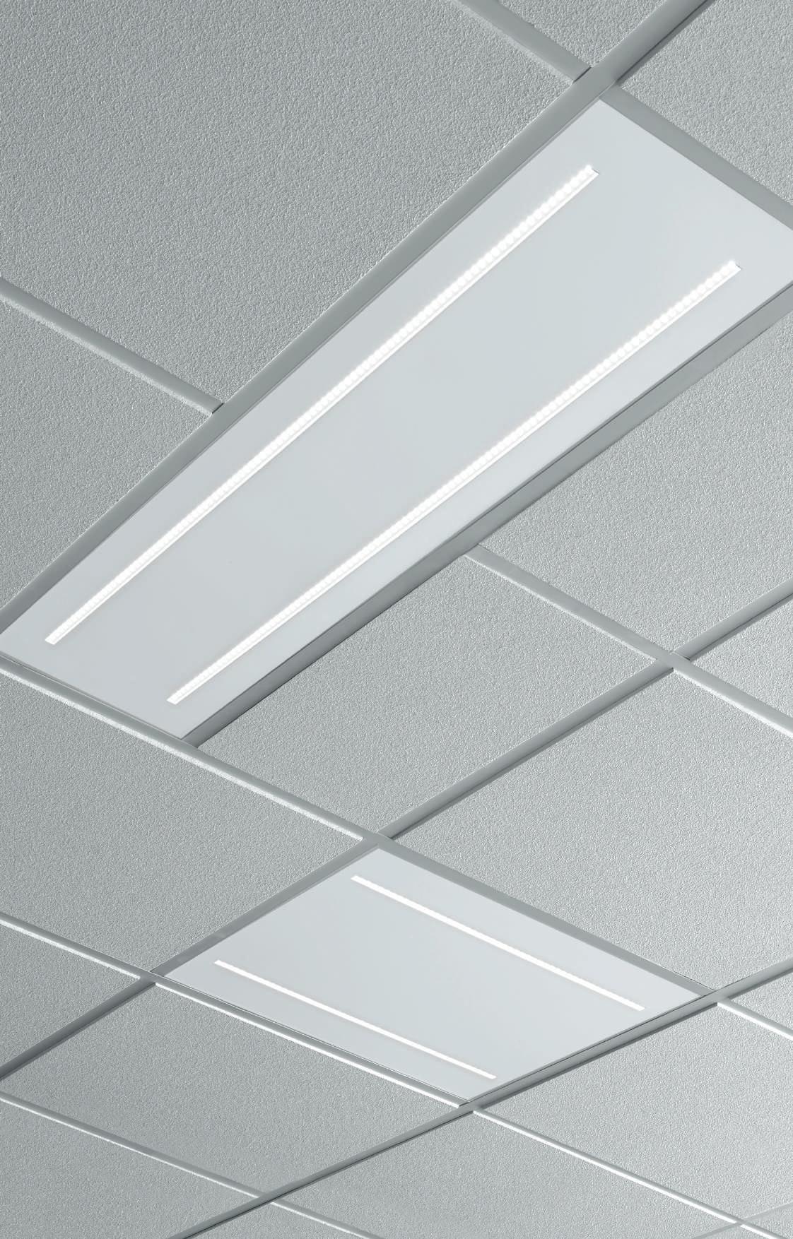
THE PANEL BIEMISSIONE
Pannello LED 1200x300 mm ad emissione diretta-indiretta. Cornice in lega di alluminio verniciata a polvere di colore bianco, diffusore opale e rosone in acciaio verniciato bianco.
UGR<19 4H-8H, S=0.25, indice di riflessione 70-50-20. Alimentatore elettronico e accessori per la sospensione inclusi.
LED panel 1200x300 mm made of white powder coated aluminum alloy and canopy white painted steel. UGR<19 4H-8H, S=0.25, reflexion index 70-50-20. Electronic driver and accessories for suspension included.
THE PANEL BIEMISSIONE
ACCESSORI ACCESSORIES
KIT n.2 GIUNTI (privi di sospensioni)
KIT nos.2 JOINTS (without suspensions)
16232.96
550 55 max 1000 40 1196 296 11 35% 65%
UGR <19 220-240V 50/60Hz PUSH IP 40 RISCHIO FOTOBIOLOGICO GRUPPO 0 DESIGNED IN ITALY POWER FLUX 3000K FLUX 4000K 33W 4185 lm 105601.01 4545 lm 105602.01 DALI-PUSH POWER FLUX 3000K FLUX 4000K 33W 4185 lm 105603.01 4545 lm 105604.01 2x
CODE
C.A.M. Edilizia 21 LED PANEL THE PANEL BIEMISSIONE
22
THE PANEL IP65
THE PANEL 2 - IP65 600x600
Altezza minima per installazione 60 mm.
Minimum height for installation 60 mm.
THE PANEL IP65
ACCESSORI
BOX PER INSTALLAZIONE A PLAFONE
Kit da assemblare, non installabile a parete.
KIT FOR CEILING MOUNTING
To be assembled, not suitable for wall surface mounting.
KIT PER INSTALLAZIONE
AD INCASSO A RASAMENTO
Profilo da rasare su cartongesso di spessore 12,5 mm.
Il pannello si installa in appoggio.
KIT FOR LEVELLED RECESSED INSTALLATION
Profile to be levelled on 12,5 mm thick plasterboard.
KIT ANTICADUTA
Cavo in acciaio da fissare a soffitto o strutture tramite morsetto in ottone nichelato e aggancio a vite sul pannello.
ANTI FALL-OUT KIT
Steel cable to be fixed to the ceiling or structures using a nickel-plated brass clamp and screwed on the panel.
CAVI DI SOSPENSIONE (4 pz.) regolabili, in acciaio con terminali in ottone cromato.
SUSPENSION CABLES (4 pcs) adjustable, made of steel with tile pipes in chromed brass.
Pannello LED con grado di protezione IP65 totale. Cornice in lega di alluminio verniciata a polvere di colore bianco, diffusore opale. Installabile ad incasso su controsoffitto a pannelli con struttura a vista senza accessori, ad incasso su cartongesso liscio con kit profilo da rasare, e a plafone con Box (solo per interni). Alimentatore elettronico incluso, da collegare tramite opportuni connettori stagni.
Global protection index IP65 LED panel. Frame made of white powder coated aluminium alloy, opal diffuser. No accessories needed for installation on exposed grid ceiling, kit for levelled recessed installation required for standard plasterboard, and Box for ceiling surface installation (only indoor). Included electronic driver, to be connected to the fixture by sealed connectors.
Altezza minima per installazione 60 mm Minimum height for installation 60 mm 595 595 11 12,5 H 100 L 640 W 640
ACCESSORIES
POWER FLUX 3000K FLUX 4000K 36W 3723 lm 105501.01 4137 lm 105502.01
220-240V 50/60Hz IK 09 IP 65
CODE L (mm) 102028.99 600x600 C.A.M. Edilizia RISCHIO GRUPPO 0
CODE L (mm) 105503.99 3000 2x L ø16 ø10 x4
CODE L (mm) 104429.99 3000 84 54 50
POWER SUPPLY KIT FOR SUSPENSION
power cable CODE L (mm) Cavo / Cable (mm2) 108919.01 1200 3x1,5 108920.01 3000 3x1,5 600 43 600
KIT DI ALIMENTAZIONE PER SOSPENSIONE Cavo di alimentazione trasparente
Transparent
CODE VERSION 102086.01 600x600 23 LED PANEL THE PANEL IP65
24
FRAME PANEL
Cornice luminosa LED in lega di alluminio verniciata a polvere di colore bianco Installabile ad incasso su controsoffitto a pannelli con struttura a vista senza accessori, o su cartongesso liscio con apposito accessorio da ordinare a parte. Alimentatore elettronico incluso.
LED made of aluminum alloy, powder-coated in white colour Suitable for installation on exposed grid ceiling. Can be flush recessed with a special kit to be ordered separately. Electronic power supply included.
Per sopperire alle attuali problematiche di reperibilità dei componenti elettronici, disponiamo di articoli alternativi (non combinabili) di pari caratteristiche tecniche. In order to meet the current problems of availability of electronic components, we have alternative items (not combinable) of the same technical features.
FRAME PANEL
Diffusore opale complanare al piano del soffitto.
Pannello di chiusura da rifilare prima di essere alloggiato all’interno del prodotto.
Levelled recessed opal diffuser. The closing panel to be trimmed before being housed inside the product.
FRAME PANEL TL
Diffusore opale sporgente rispetto al piano del soffitto.
Pannello di chiusura da forare per il passaggio cavo di alimentazione.
Protruding opal screen with respect to the ceiling level. The closing panel must be drilled to allow the passage of the panel power cable.
FRAME PANEL
ACCESSORI ACCESSORIES
KIT PER INSTALLAZIONE AD INCASSO A RASAMENTO Profilo da rasare su cartongesso di spessore 12,5 mm. Il pannello si installa in appoggio.
KIT FOR LEVELLED RECESSED INSTALLATION
Profile to be levelled on 12,5 mm thick plasterboard.
KIT ALIMENTAZIONE IN EMERGENZA Completo di connettori polarizzati per il collegamento dell’alimentatore.
KIT FOR EMERGENCY Polarizad connectors included.
CODE L (mm) 102028.99 600x600
595 595 595 595 12,5 H 100 L 640 W 640 C.A.M. Edilizia POWER FLUX 3000K FLUX 4000K 35W 3150 lm 104701.01 3214 lm 104702.01 DALI-PUSH POWER FLUX 3000K FLUX 4000K 35W 3150 lm 104709.01 104705.01 3214 lm 104710.01 104706.01 POWER FLUX 3000K FLUX 4000K 35W 3860 lm 104703.01 4015 lm 104704.01 DALI-PUSH POWER FLUX 3000K FLUX 4000K 35W 3860 lm 104711.01 104707.01 4015 lm 104712.01 104708.01
220-240V 50/60Hz IP 40
RISCHIO FOTOBIOLOGICO GRUPPO 0 IP 20
CODE TIME CHARGE A (mm) D (mm) H (mm) L (mm) 1020A4.99 1h 12h 38 44 25 164 1020A5.99 3h 12h 38 44 25 164 Flusso in emergenza - Emergency flux 1h 3h FRAME PANEL 35W 12% 5% FRAME PANEL TL 35W 12% 5% A H L D
25 LED PANEL FRAME PANEL
26
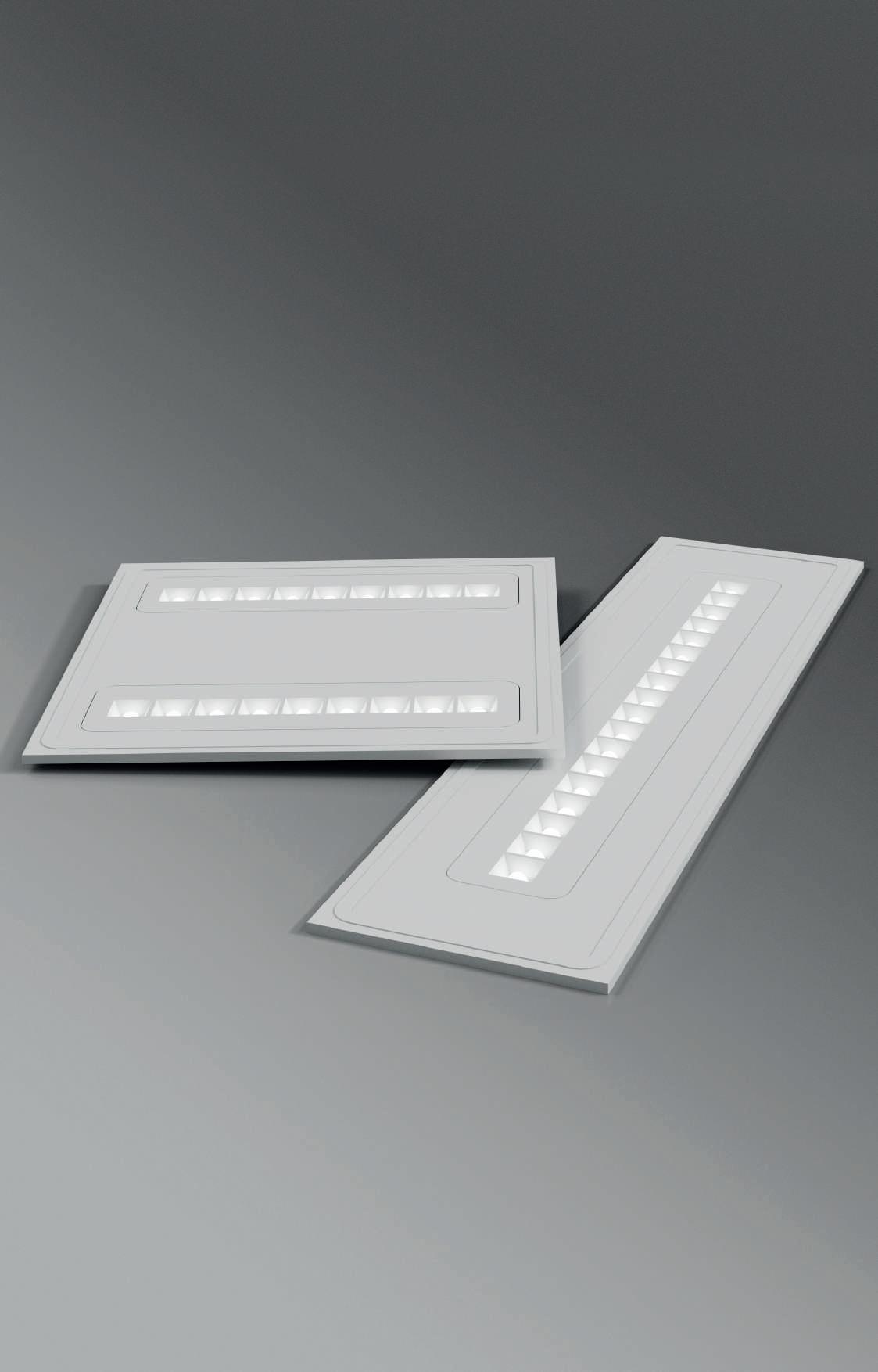
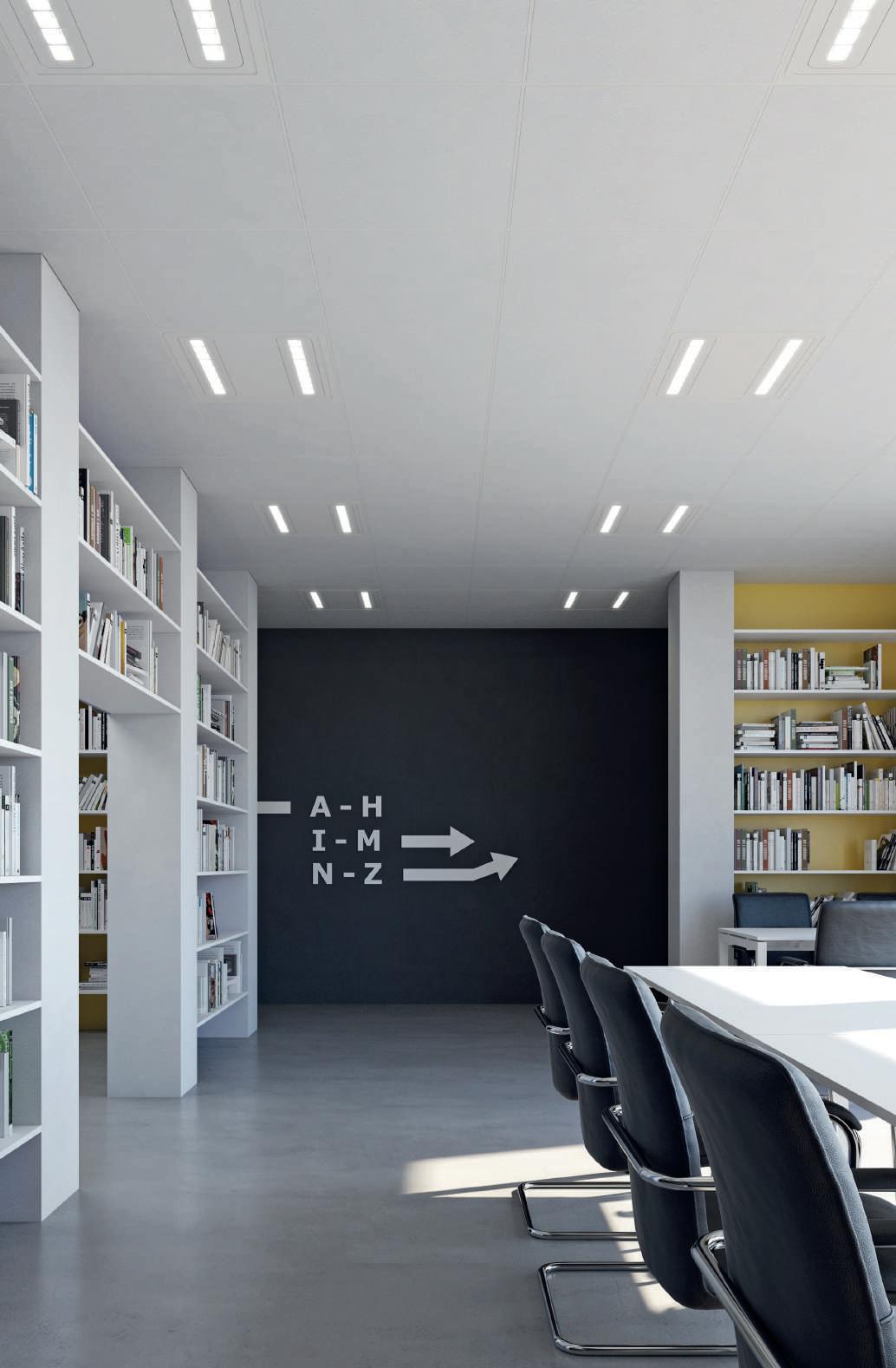
Pannello LED in lamiera in acciaio verniciata a polvere e lenti in metacrilato. UGR<19, luminanza <3000cd/m² per angoli γ>65° Installabile ad incasso su controsoffitto a pannelli con struttura a vista senza accessori, per le altre installazioni prevedere gli opportuni accessori da ordinare a parte. Alimentatore elettronico incluso.
LED panel made of powder coated steel body and methacrylate lenses. UGR<19, luminance <3000cd/m² for angles γ>65°. No accessories needed for installation on exposed grid ceiling, accessories for other installations to be ordered separately. Integrated electronic driver.
POWER FLUX 4000K 30W 4000 lm 104129.01 DALI-PUSH POWER FLUX 4000K 30W 4000 lm 104130.01 595 14 595 595 595 14 1195 295 14 DESIGNED IN ITALY
UGR <19 220-240V 50/60Hz PUSH IP 40
SCHOOL
continuità estetica School UV-C
aesthetic continuity School UV-C SCHOOL 1200x300 * CRI >90 FOTOBIOLOGICO GRUPPO 0 POWER FLUX 4000K 20W 2665 lm 104115.01 30W 4000 lm 104101.01 DALI-PUSH POWER FLUX 4000K 20W 2665 lm 104118.01 30W 4000 lm 104113.01 POWER FLUX 4000K 30W 4100 lm 104111.01 50W 6832 lm 104104.01 DALI-PUSH POWER FLUX 4000K 30W 4100 lm 104112.01 50W 6832 lm 104114.01
SCHOOL
SCHOOL 600x600
600x600 Per
For
C.A.M. Edilizia
27 LED PANEL SCHOOL
* Solo versione DALI-PUSH / Only DALI-PUSH version
ACCESSORI PER INSTALLAZIONE AD INCASSO ACCESSORIES FOR RECESSED MOUNTING


KIT MOLLE PER INSTALLAZIONE AD INCASSO


Per versioni 600x600 e 1200x300, per installazione in battuta in cartongesso di spessore 10÷20 mm.
SPRINGS KIT FOR RECESSED INSTALLATION
For 600x600 and 1200x300 versions, for installation by frame contrasting in plasterboard of thickness 10÷20 mm.


CODE 104107.99


KIT PER INSTALLAZIONE AD INCASSO A RASAMENTO Profilo da rasare su cartongesso di spessore 12,5 mm. Il pannello si installa in appoggio.
KIT FOR LEVELLED RECESSED INSTALLATION Profile to be levelled on 12,5 mm thick plasterboard.
Prevedere una zona libera per il profilo di almeno 40 mm di distanza dal taglio. Reserve a free space for the profile of at least 40 mm away from the cut.
SCHOOL
12,5 H 100 L 640 W 640 8x 10 ÷ 20 12,5 H 100 L 1240 W 340
VERSION (mm) 102028.99 600x600 102029.99 1200x300 H 50 L 575 W 575 H 50 L 1175 W 275
FALL-OUT KIT CODE L (mm) 104119.99 3000 28 LED PANEL
CODE
KIT ANTICADUTA ANTI
ACCESSORI PER INSTALLAZIONE A PLAFONE ACCESSORIES FOR
KIT PER INSTALLAZIONE A PLAFONE Altezza totale, compreso apparecchio, 40 mm Accessorio opzionale per installazione a sospensione.
KIT FOR CEILING MOUNTING
Overall height, including lihting fixture, 40 mm Optional accessory for suspended mounting.

CODE VERSION
BOX PER INSTALLAZIONE A PLAFONE In estruso di alluminio. Kit da assemblare, non installabile a parete.
KIT FOR CEILING MOUNTING In extruded aluminium. To be assembled, not suitable for wall surface mounting.
CODE VERSION

SCHOOL
CEILING
565 565 22 1165 265 22
MOUNTING
104108.01 600x600 104109.01 1200x300
300 43 1200 600 43 600 29 LED PANEL SCHOOL
102086.01 600x600 102087.01 1200x300
ACCESSORI PER INSTALLAZIONE A SOSPENSIONE ACCESSORIES FOR SUSPENSION MOUNTING
CAVI DI SOSPENSIONE (4pz) per versioni 600x600 e 1200x300. Accessorio compatibile con il kit per installazione a plafone 104108.99/104109.99.

SUSPENSION CABLES (4pcs) For 600x600 and 1200x300 versions Suitable for the kit for ceiling mounting 104108.99/104109.99.


KIT DI ALIMENTAZIONE PER SOSPENSIONE
ACCESSORI EMERGENZA ACCESSORIES EMERGENCY
KIT DI ALIMENTAZIONE IN EMERGENZA Completo di connettori polarizzati per il collegamento dell’alimentatore.
KIT FOR EMERGENCY Polarized connectors included.
LED PANEL SCHOOL SCHOOL
IP 20 CODE TIME CHARGE A (mm) D (mm) H (mm) L (mm) 1020A4.99 1h 12h 38 44 25 164 1020A5.99 3h 12h 38 44 25 164 Flusso in emergenza - Emergency flux 1h 3h SCHOOL 20W 20% 8% SCHOOL 30W 13% 5% SCHOOL 50W 8% 3% A H L D 84 54 50 L 4x
POWER SUPPLY KIT FOR SUSPENSION CODE L (mm) Cavo / Cable (mm2) 108919.01 1200 3x1,5 108921.01 1200 5x1,5 CODE L (mm) 104110.99 1200 30
31 LED PANEL SCHOOL
32
SCHOOL UV-C
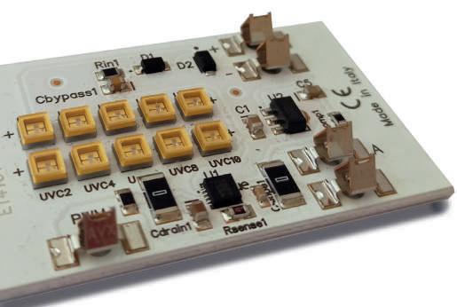
Apparecchio provvisto di LED per illuminazione ambiente e di LED UV-C ad azione sanificante e germicida, gestibile con accensioni separate, con possibilità di temporizzazione del comparto UV-C tramite dispositivo esterno. Un importante ausilio in un piano di protezione e sanificazione dell’ aria in ambito civile, residenziale, ambulatoriale, ricettivo, scolastico ecc, contro batteri, funghi e virus. Installabile ad incasso su struttura a vista o in appoggio su profili da rasare, o a sospensione.
Fixture provided with LED light and UV-C LED that has a sanitizing and germicidal action, managed by double switch, with the possibility of timing of the UV-C compartment via external device.
An important help for an air sanification and protection plan, in civil, residential, outpatient, receptive, scholastic sector ecc. against bacteria, fungi and viruses.
Suitable for recessed installation on exposed grid ceiling or with profile for plasterboard, to be ordered separately, and suspension intallation.
AD
CAVI DI SOSPENSIONE (4pz)
Accessorio compatibile con il kit per installazione a plafone.
SUSPENSION CABLES (4pcs)
Suitable for the kit for ceiling mounting
KIT DI ALIMENTAZIONE IN EMERGENZA Completo di connettori polarizzati per il collegamento dell’alimentatore.
65 65
595 14 595 12,5 H 100 L 640 W 640
KIT ANTICADUTA ANTI FALL-OUT KIT CODE L (mm) 104119.99 3000 84 54 50 KIT DI ALIMENTAZIONE PER SOSPENSIONE POWER SUPPLY KIT FOR SUSPENSION
108921.01 1200
ACCESSORI ACCESSORIES L 4x
KIT PER INSTALLAZIONE
INCASSO A RASAMENTO Profilo da rasare su cartongesso di spessore 12,5 mm. Il pannello si installa in appoggio. KIT FOR LEVELLED RECESSED INSTALLATION Profile to be levelled on 12,5 mm thick plasterboard. CODE 102028.99
CODE L (mm) Cavo / Cable (mm2)
5x1,5 SCHOOL UV-C
CODE
104110.99 1200
L (mm)
RISCHIO FOTOBIOLOGICO GRUPPO 0 UGR <19 220-240V 50/60Hz PUSH IP 20 * CRI >90 C.A.M. Edilizia * Solo versione DALI-PUSH / Only DALI-PUSH version POWER LED POWER LED UV-C FLUX 4000K 30W 5W 4000 lm 104122.01 DALI-PUSH POWER LED POWER LED UV-C FLUX 4000K 30W 5W 4000 lm 104128.01
KIT FOR EMERGENCY Polarized connectors included. IP 20 CODE TIME CHARGE A (mm) D (mm) H (mm) L (mm) 1020A4.99 1h 12h 38 44 25 164 1020A5.99 3h 12h 38 44 25 164 Flusso in emergenza - Emergency flux 1h 3h SCHOOL UV-C 13% 5% A H L D 33 LED PANEL SCHOOL UV-C
OBIETTIVO SANIFICAZIONE
Quando si parla di sanificazione ambientale non ci si deve limitare al concetto di pulizia ordinaria che viene effettuata quotidianamente con i tradizionali metodi e prodotti. In ambienti come uffici, scuole, ambulatori, palestre, che vengono frequentati anche da un elevato numero di persone per molte ore consecutive, un intervento di sanificazione che operi in maniera massiva su batteri e virus è fondamentale, soprattutto in questo periodo storico in cui la quotidianità di ciascuno di noi è fortemente condizionata dal COVID-19. Novalux ha sviluppato un prodotto che permette di vivere, lavorare e studiare respirando aria sanificata, per la sicurezza di tutti.
SANITIZATION OBJECTIVE
When we speak of environmental sanitation we must not limit ourselves to the concept of ordinary cleaning that is carried out daily with traditional methods and products. In environments such as offices, schools, clinics, gyms, which are also frequented by a large number of people for many consecutive hours, a sanitization intervention that operates massively on bacteria and viruses is essential, especially in this historical period in which the everyday life of each of us is strongly conditioned by the COVID-19. Novalux has developed a product that allows you to live, work and study breathing air sanitized, for the safety of all.
LA SOLUZIONE SCHOOL
School UV-C è un apparecchio che sfrutta la tecnologia dei LED UV-C per ridurre la carica microbiologica presente nell’aria. Associandolo ai pannelli School 30W standard, si ottiene la soluzione ideale per illuminare locali come aule scolastiche e uffici, e al contempo garantire un’efficacie azione di sanificazione dell’aria, senza interferire con le abitudini delle persone.
THE SCHOOL SOLUTION
School UV-C is a fixture that uses UV-C LED technology to reduce the microbiological charge present in the air. By combining it with the standard School 30W panels, you get the ideal solution to light rooms such as classrooms and offices, and at the same time ensure an effective air sanitization action, without interfering with people’s habits.
34 LED PANEL
SCHOOL UV-C
- Azione sanificante con ricircolo dell’aria (30m3/h)
- Forced recirculation air sanitizing action (30m3/h)
- No emissioni UV-C né ozono
- Neither UV-C nor ozone emission
- Possibilità di utilizzo diurno in presenza di persone
- Possible day use in the presence of people
- Non inquinante
- Non-polluting
- LED UV-C 25.000h funzionamento
- LED UV-C operating 25.000h
COME FUNZIONA?
Il sistema di aspirazione a ventola immette aria, per una portata di 30m3/h, all’interno della camera contenente la sorgente LED UV-C, dove avviene il processo di sanificazione. La camera è opportunamente trattata con un materiale altamente riflettente per una lunghezza d’onda di 275nm, per migliorare l’efficienza del sistema di sanificazione. Non sono presenti filtri di alcun genere, pertanto il prodotto non richiede manutenzione né smaltimento degli stessi, e non può essere causa di allergie da muffe.
- Certificato UNI EN ISO15714:2019
- UNI EN ISO15714:2019 certificated


- Senza filtri: nessuna manutenzione, smaltimento o allergie da muffe
- Without filters: no maintenance, disposal or mold allergies
- Ridotta rumorosità: 20dB
- Reduced noise: 20dB
- Lunghezza d’onda LED UV-C: 275 nm

- UV-C Wavelength: 275 nm
HOW DOES IT WORK?
For a flow rate of 30m3/h, the fan suction system injects air into the chamber containing the UV-C LED source, where the sanitization process takes place. The chamber is suitably treated with a highly reflective material for a wavelength of 275nm, to improve the efficiency of the sanitization system. There are no filters of any kind, therefore the product does not require maintenance or disposal of the same, and can not be cause of allergies from mold.
 ventola fan
LED UV-C frangiluce light trap
ventola fan
LED UV-C frangiluce light trap
camera di sanificazione sanification chamber 35 LED PANEL SCHOOL UV-C
frangiluce light trap
TEST DI LABORATORIO
L’efficacia di School UV-C è stata testata seguendo i requisiti della norma UNI-EN ISO 15714.2019, comprendendo i seguenti microrganismi di prova: virus, batteri gram positivi, batteri gram negativi e funghi. I risultati di trattamento ottenuti hanno evidenziato valori di disinfezione fino al 99,9%.
UN PRODOTTO SICURO
I LED UV-C inibiscono la riproduzione dei microorganismi agendo direttamente sul DNA o sull’RNA di virus, batteri, muffe, lieviti e spore presenti nell’ambiente. L’esposizione diretta ai raggi UV-C è però dannosa per l’uomo e altre forma di vita, per questo il pannello School UV-C è dotato di un sistema a camera chiusa che scherma i raggi e ne impedisce il contatto diretto con le persone. Inoltre, la tecnologia utilizzata non genera ozono, altro potenziale pericolo per l’uomo.
Il livello di sicurezza garantito da School UV-C è tale per cui può essere tranquillamente utilizzato anche in presenza di persone.
A SAFE PRODUCT
UV-C Leds inhibit the reproduction of microorganisms by acting directly on DNA or RNA of viruses, bacteria, moulds, yeasts and spores present in the environment. However, direct exposure to UV-C rays is harmful to humans and other life forms, which is why the School UV-C panel is equipped with a closed-chamber system that shields the rays and prevents direct contact with people. Furthermore, the technology used does not generate ozone, another potential danger for man. The level of safety guaranteed by School UV-C is such that it can be safely used even in the presence of people.
THE LAB TEST
The effectiveness of School UV-C has been tested according to the requirements of UNI-EN ISO 15714.2019, including the following test microorganisms: viruses, gram positive bacteria, gram negative bacteria and fungi. The treatment results obtained showed disinfection values of up to 99.9%.
RISULTATI TEST DI LABORATORIO LABORATORY TEST RESULTS TEMPO TIME % RIDUZIONE MICROBICA % MICROBIAL REDUCTION 0 0% 1 hour 59% 2 hours 63% 3 hours 63% 4 hours 81% 5 hours 99% CONTA SU COLONIE TOTALI 0 20 40 60 80 100 120 TEMPO 0 1 ORA 2 ORE 3 ORE 4 ORE5 ORE CONTA SU COLONIE TOTALI SCHOOL UV-C 36 LED PANEL
SCHOOL UV-C SCHOOL 30W Ufficio/Office 67m3 500lx Aula/Classroom 135m3 300lx Open space 110m3 500lx Aula magna/Auditorium 240m3 500lx Locale Room mq H (m) Illuminamento medio Average illuminance n° School 30W TOTALI TOTAL n° of School 30W School UV-C 30W Tempo di sanificazione (ore) Sanification time (hours) Ufficio/Office 25 2,70 500lx 4 1 3 Open space ufficio/Office 42 2,70 500lx 6 1 5 Aula/Classroom 50 2,70 300lx 6 1 7 Aula magna/Auditorium 80 3,00 500lx 12 2 6 37 LED PANEL SCHOOL UV-C
38
YALE
Pannello LED in lamiera di acciaio verniciata a polvere, lenti in policarbonato e riflettori in tecnopolimero. UGR<19. Installabile ad incasso su controsoffitto a pannelli 600x600mm con struttura a vista senza accessori o ad incasso a rasamento con profilo da rasare da ordinare a parte. Installabile a plafone con apposito box. Alimentatore elettronico Incluso.
LED panel made of powder coated steel body, polycarbonate lens and technopolymer reflectors. UGR<19.
No accessories needed for exposed grid ceiling, or kit for levelled recessed installation to be ordered separately. Box required for ceiling mounting. Integrated electronic driver.
Per sopperire alle attuali problematiche di reperibilità dei componenti elettronici, disponiamo di articoli alternativi (non combinabili) di pari caratteristiche tecniche. In order to meet the current problems of availability of electronic components, we have alternative items (not combinable) of the same technical features.
UGR <19 220-240V 50/60Hz PUSH IP 40 * CRI >90 RISCHIO GRUPPO 0 10 595 595 25
YALE 600x600 YALE 1200x300 POWER FLUX 4000K 30W 4082 lm 109501.01 DALI-PUSH POWER FLUX 4000K 30W 4082 lm 109505.01 109503.01 POWER FLUX 4000K 30W 4509 lm 109502.01 DALI-PUSH POWER FLUX 4000K 30W 4509 lm 109506.01 109504.01 10 1195 295 25 10 1195 295 25 * Solo versione DALI-PUSH / Only DALI-PUSH version C.A.M. Edilizia
39 LED PANEL YALE
KIT PER INSTALLAZIONE AD INCASSO A RASAMENTO
Profilo da rasare su cartongesso di spessore 12,5 mm. Il pannello si installa in appoggio.
KIT FOR LEVELLED RECESSED INSTALLATION
Profile to be levelled on 12,5 mm thick plasterboard.
KIT
BOX PER INSTALLAZIONE A PLAFONE
In estruso di alluminio. Kit da assemblare, non installabile a parete. Idoneo per alloggiamento del kit di emergenza (1020A4.99/1020A5.99).
BOX FOR CEILING MOUNTING
In extruded aluminium. To be assembled, not suitable for wall surface mounting. Suitable for emergency kit (1020A4.99/1020A5.99).
KIT ALIMENTAZIONE IN EMERGENZA Per versioni 600x600 e 1200x300. Completo di connettori polarizzati per il collegamento dell’alimentatore.
KIT FOR EMERGENCY For 600x600 and 1200x300 versions. Polarized connectors included.
LED PANEL
ACCESSORI ACCESSORIES YALE
CODE VERSION (mm) 102086.01 600x600 102087.01 1200x300 IP 20 12,5 H 100 L 640 W 640 12,5 H 100 L 1240 W 340
ANTICADUTA ANTI FALL-OUT KIT CODE VERSION (mm) 102028.99 600x600 102029.99 1200x300 CODE L (mm) 104119.99 3000 300 43 1200 600 43 600
CODE TIME CHARGE A (mm) D (mm) H (mm) L (mm) 1020A4.99 1h 12h 38 44 25 164 1020A5.99 3h 12h 38 44 25 164 Flusso in emergenza - Emergency flux 1h 3h YALE 600x600 30W 14% 5% YALE 1200X300 30W 14% 6% A H L D 40
LED PANEL 41 YALE
42
DOWNLIGHT
43
44
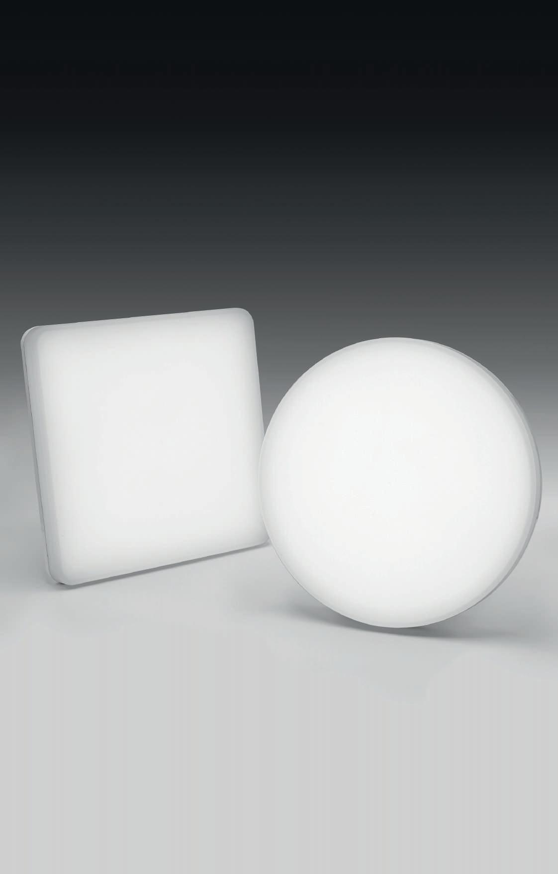
SLIM
Apparecchio LED per installazione ad incasso in battuta in controsoffitto. Cornice e corpo dissipante in lega di alluminio pressofusa verniciata bianca. Schermo diffusore in policarbonato opale e molle in acciaio armonico per il fissaggio a controsoffitto di spessore fino a 15 mm. Alimentazione elettronica inclusa, da collocare a lato del prodotto.
LED fixture for false ceiling recessed installation. Frame and dissipater made of die-casting aluminum alloy, white painted. Diffuser made of opal polycarbonate and clips made of harmonic steel, for fixing to the false ceiling of thickness up to 15 mm. Electronic driver included, to be placed next to the fixture.
SLIM QUADRATO SLIM SQUARE
ACCESSORI ACCESSORIES
ADATTATORE PER SLIM TONDO 20W per installazione in foro da incasso 240-250 mm, con molle.
ADAPTOR FOR SLIM ROUND 20W For recessed installation hole 240-250 mm, clips included.
ALIMENTATORE ELETTRONICO
DIMMERABILE 220-240V 50/60Hz
Per il collegamento in serie di max 2 Slim 9W, 1 Slim 13W o 1 Slim 20W.
ELECTRONIC DIMMABLE DRIVER 220-240V 50/60Hz For connection in series of max
2 Slim 9W, 1 Slim 13W or 1 Slim 20W.
220-240V 50/60Hz IP 40
POWER L (mm) H (mm) FLUX 3000K FLUX 4000K 9W 110 24 882 lm 11826.01 959 lm 11825.01 13W 160 26 1367 lm 11824.01 1491 lm 11823.01 20W 230 28 2110 lm 11822.01 2279 lm 11821.01 H 100 L 95 W 95 H 100 L 145 W 145 H 100 L 210-215 W 210-215 9W 13W 20W RISCHIO FOTOBIOLOGICO GRUPPO 0
CODE D (mm) 11814.01 280 CODE POWER A (mm) D (mm) H (mm) L (mm) 101333.99 25W 52 55 23 120 IP 20 PUSH IP 20 SLIM L H ø H SLIM TONDO SLIM ROUND POWER Ø (mm) H (mm) FLUX 3000K FLUX 4000K 9W 125 25 950 lm 11820.01 970 lm 11819.01 13W 160 26 1210 lm 11818.01 1280 lm 11817.01 20W 230 28 1950 lm 11816.01 2000 lm 11815.01 H 100 ø 110 H 100 ø 145 H 100 ø 210-215 9W 13W 20W CRI >90 L A H D 26,5 11,5 D ø240-250 26,5 11,5 D ø240-250 C.A.M. Edilizia
lato
prodotto.
false ceiling
Flusso in emergenza Emergency flux 1h 3h SLIM 9W 53% 21% SLIM 13W 35% 14% SLIM 20W 22% 9% CODE TIME CHARGE A (mm) D (mm) H (mm) L (mm) 18004.99 1h 12h 38 44 25 164 18005.99 3h 12h 38 44 25 164 A H L D 45 DOWNLIGHT SLIM
KIT DI EMERGENZA da installare sul controsoffitto a
del
EMERGENCY KIT to place on the
next to the fixture.
46
CREP
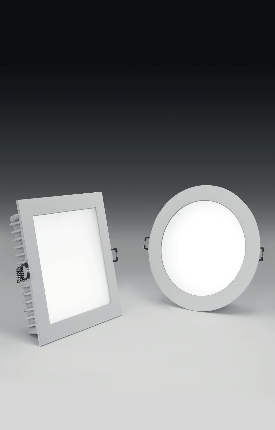
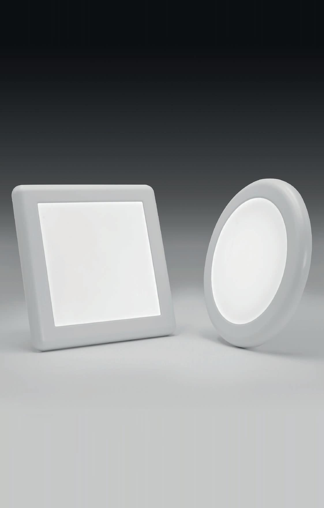
Apparecchio LED per installazione a plafone o ad incasso in battuta in controsoffitto. Temperatura di colore delle sorgenti selezionabile con selettore sul retro dell’apparecchio in 3000K, 4000K o 5400K. Disponibile in due dimensioni, potenza totale settabile tra tre disponibili. Corpo in policarbonato e schermo diffusore in polistirene opale. Staffa di installazione in acciaio. Molle in acciaio armonico per fissaggio su controsoffitto di spessore fino a 15 mm, che permettono la regolazione in funzione della dimensione del foro da incasso disponibile. Alimentazione elettronica inclusa, integrata nel corpo dell’apparecchio.
LED fixture for ceiling or recessed installation in false ceiling. Source color temperature, selectable with selector on the back of the fixture in 3000K, 4000K or 5400K. Two sizes are available, total power adjustable between three available. Polycarbonate body and diffuser screen in opal polystyrene. Steel installation bracket. Springs in harmonic steel for fastening to false ceiling thickness up to 15 mm, which allow adjustment according to the size of the recessed hole available. Electronic power supply included, integrated in the body of the fixture.
*
*
e temperatura di colore delle sorgenti selezionabili con selettore
selectable
e temperatura di colore delle sorgenti
con selettore
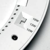
Selettore temperatura di colore delle sorgenti 3000K, 4000K o 5400K.
Color temperature selector 3000K, 4000K, or 5400K. Selettore potenza totale 10W, 13W o 16W. 16W, 20W o 22W.
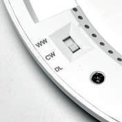
Total power selector 10W, 13W or 16W. 16W, 20W or 22W.
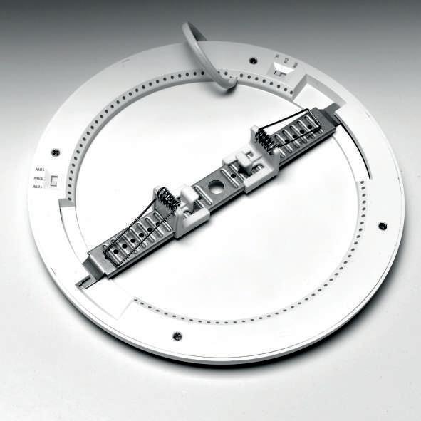
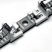
Molle regolabili per installazione a contosoffitto,removibili per installazione a plafone. Adjustable springs for ceiling installation, removable for ceiling installation.
IP 20 220-240V 50/60Hz
RISCHIO FOTOBIOLOGICO GRUPPO 0
16/20 ø 25 16/20 L 25 CREP TONDO CREP ROUND CREP QUADRATO CREP SQUARE POWER variable* Ø (mm) H (mm) FLUX 10W / 13W / 16W 235 16 variable* 107501.01 16W / 20W / 22W 300 20 variable* 107503.01 POWER variable* L (mm) H (mm) FLUX 10W / 13W / 16W 235 16 variable* 107502.01 16W / 20W / 22W 300 20 variable* 107504.01 CREP Ø235mm LED colour FLUX / POWER 10W 13W 16W 3000K 1094 / 1387 / 1642 lm 4000K 1173 / 1516 / 1826 lm 5400K 1134 / 1447 / 1696 lm CREP Ø300mm LED colour FLUX / POWER 16W 20W 22W 3000K 1682 / 2015 / 2191 lm 4000K 1896 / 2252 / 2483 lm 5400K 1749 / 2093 / 2280 lm CREP L.235mm LED colour FLUX / POWER 10W 13W 16W 3000K 1094 / 1387 / 1642 lm 4000K 1173 / 1516 / 1826 lm 5400K 1134 / 1447 / 1696 lm CREP L.300mm LED colour FLUX / POWER 16W 20W 22W 3000K 1709 / 2061 / 2233 lm 4000K 1850 / 2260 / 2470 lm 5400K 1800 / 2163 / 2325 lm 10/13/16 W H 100 ø 65-205 10/13/16 W H 100 ø 65-205
Power and
temperature
with
Potenza
source color
selector
Potenza
Power and source
temperature
with selector 16/20/22 W H 100 ø 65-254 16/20/22 W H 100 ø 65-254 47 DOWNLIGHT CREP
selezionabili
color
selectable
48
CEILING WALL FLOOR
49
50
LUNA
Apparecchio LED per installazione a plafone o a parete. Base in policarbonato bianco, diffusore in policarbonato ad elevata trasmittanza Disponibili versione con emergenza 1h integrata, e versione con sensore di presenza e luminosità. Alimentazione elettronica inclusa
LED fixture for wall or ceiling surface mounting. Polycarbonate base in white color, polycarbonate diffuser with high transmittance 1h emergency version and presence/daylight detector version available. Electronic driver included.
SENSORE DI PRESENZA - WITH PRESENCE DETECTOR
di attesa 90s. Soglia diurna 20lux / Delay time 90sec. Daylight
ø H 32 L 32 H CRI >90 FOTOBIOLOGICO GRUPPO 0 220-240V 50/60Hz IP 44
LUNA
LUNA TONDO LUNA ROUND LUNA QUADRATO
SQUARE
POWER Ø (mm) H (mm) FLUX 3000K FLUX 4000K 19W 280 48 1996 lm 104315.01 2036 lm 104316.01 36W 400 48 3990 lm 104317.01 4209 lm 104318.01 POWER Ø (mm) H (mm) FLUX 3000K FLUX 4000K 19W 280 58 1996 lm 104325.01 2036 lm 104326.01 36W 400 58 3990 lm 104327.01 4209 lm 104328.01 POWER L(mm) H (mm) FLUX 3000K FLUX 4000K 19W 280 48 1991 lm 104319.01 2031 lm 104320.01 36W 400 48 4090 lm 104321.01 4314 lm 104322.01 POWER Ø (mm) H (mm) FLUX 3000K FLUX 4000K 19W 280 48 1996 lm 104329.01 2036 lm 104330.01 POWER Ø (mm) H (mm) FLUX 3000K FLUX 4000K 19W 280 58 1996 lm 104331.01 2036 lm 104332.01 36W 400 58 3990 lm 104333.01 4209 lm 104334.01
Tempo
sensitivity 20lux DALI-PUSH EMERGENCY 1H Flusso in emergenza / Emergency flux 19W 7% / 36W 8% C.A.M. Edilizia PUSH NEW 51 LUNA CEILING / WALL / FLOOR
CON
52
KIT SOSPENSIONE Cavi in acciaio L 2000 mm con terminale in ottone cromato.
SUSPENSION KIT Steel cables L 2000 mm with tile pipes made of chromed brass.
KIT DI ALIMENTAZIONE PER SOSPENSIONE rosone ad incasso in controsoffitto di spessore da 5 a 15 mm. Cavo con guaina bianca.
POWER SUPPLY FOR SUSPENSION recessed ceiling mounted canopy for thickness from 5 up to 15 mm. Cable with white sheath.
KIT DI ALIMENTAZIONE PER SOSPENSIONE rosone a plafone. Cavo con guaina bianca.
POWER SUPPLY FOR SUSPENSION ceiling mounted canopy. Cable with white sheath.
STAFFE PARETE (2 pz.)
WALL BRACKETS (2 pcs)
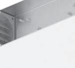
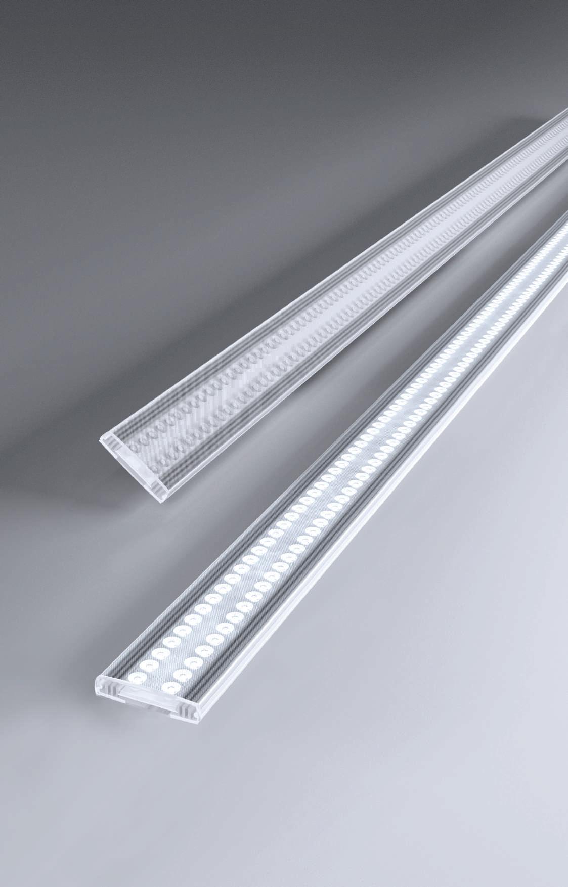
Profilo dissipante per Strip LED in lega di alluminio verniciata bianca, testate di chiusura in polimero termoplastico, schermo diffusore ad inserimento a scatto in PMMA opale. Schermo diffusore e testate di chiusura inclusi. Kit di sospensione, staffe per installazione a parete, strip LED e alimentatore 24Vdc da ordinare a parte.
Non esporre a intemperie o luce solare diretta e non inserire in materiale isolante.
Dissipating profile for Strip LED made of white powder coated aluminium alloy, end caps made of thermoplastic polymer, screen made of opal finish PMMA. Diffuser and end caps included.
Suspension kit, wall brackets, strip LED and driver 24Vdc to be ordered separately. Do not expose to bad weather or direct sunlight and do not insert into insulating material.
GIUNTO LINEARE (1 pz.)
LINEAR JUNCTION (1 pc)
TESTATE DI CHIUSURA (2 pz.)
Da prevedere in caso di utilizzo di sezioni di profilo tagliate in opera.
END CAPS (2 pcs)
To be used for sections of profile cut on site.
STRIP LED Pag. 80
CODE 105414.99
Per ottenere uniformità di luminanza nelle installazioni con schermo a vista, utilizzare strip LED 19,2W/m, 22W/m, 8,8W/m (24Vdc), o 17W/m (48Vdc).
To achieve luminance uniformity when installed with clearly visible diffusors, the strip LED to be used is 19,2W/m, 22W/m, 8,8W/m (24Vdc), or 17W/m (48Vdc).
L ø20
PROFILED TONDO PROFILED TONDO
IP 40 CODE L (mm) Diffuser 105401.01 2000 Opale / Opal ACCESSORI ACCESSORIES 75 75 45 ø65 84 54 52 CODE L (mm) 105403.99 2000
CODE L (mm) Cavo / Cable (mm2) 103320.01 1200 3x0,75
CODE L (mm) Cavo / Cable (mm2) 103319.01 1200 3x0,75
105402.01
CODE
CODE 105404.01
53 CEILING / WALL / FLOOR PROFILED
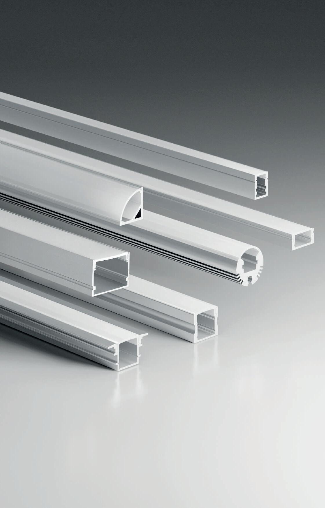
PROFILED MACRO
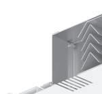
Profilo dissipante per Strip LED doppia pista 25W/m, in lega di alluminio anodizzato naturale o verniciata bianca, testate di chiusura in polimero termoplastico, schermo diffusore ad inserimento a scatto in PC opale.
Schermo diffusore, testate di chiusura e 4 staffe di fissaggio inclusi.
Strip LED e alimentatore 24Vdc da ordinare a parte.
Non esporre a intemperie o luce solare diretta e non inserire in materiale isolante. Dissipating profile for Strip LED double lane 25W/m, made of anodized aluminium alloy, natural finish or white powder coated, end caps made of thermoplastic polymer, screen made of opal finish PC.
Diffuser, end caps and 4 fixing brackets included.
Strip LED and driver 24Vdc to be ordered separately.
Do not expose to bad weather or direct sunlight and do not insert into insulating material.
CODE L (mm) Diffuser 105420.01 .96 2000 Opale / Opal
PROFILED
ACCESSORI ACCESSORIES
STAFFE DI FISSAGGIO (2 pz)
Da prevedere in caso di utilizzo di sezioni di profilo tagliate in opera.
FIXING BRACKETS (2 pcs)
To be used for sections of profile cut on site.
CODE 105422.99 Acciaio / Steel
TESTATE DI CHIUSURA (2 pz)
Da prevedere in caso di utilizzo di sezioni di profilo tagliate in opera.
END CAPS (2 pcs)
To be used for sections of profile cut on site.
CODE 105421.01 .99
fila continua
OPAL SCREEN 6 m optional
Recommended for continuous line installations
IP 40
PROFILED MACRO
CODE L (mm) 105423.99 6000 Opale / Opal SCHERMO OPALE 6 m opzionale Consigliato per installazioni in
MACRO STRIP LED DOPPIA PISTA 25W/m STRIP LED DOUBLE LANE 25W/m SMD 2835 (336 LED/m) Biadesivo - sezionabile ogni 41,6 mm (14 LED) Per profilo L-33 e Profiled MACRO Bihadesive - cuttable every 41,6 mm (14 LED) Suitable for L-33 profile and Profiled MACRO CODE LED COLOUR POWER FLUX/m L (mm) IP CRI 100916.99 2700K 25W/m 2926 5000 20 90 100917.99 3000K 25W/m 2670 5000 20 90 100918.99 4000K 25W/m 3000 5000 20 90 100925.99 2700K 25W/m 2802 5000 65 90 100926.99 3000K 25W/m 2902 5000 65 90 100927.99 4000K 25W/m 3208 5000 65 90 41,6 24 SMD 2835 (336 LED/m) Biadesivo - sezionabile ogni 41,6 mm (14 LED) Biadhesive - cuttable every 41,6 mm (14 LED) 28 L 20 30 L 54 CEILING / WALL / FLOOR
PROFILED MICRO
ACCESSORI ACCESSORIES
STAFFE DI FISSAGGIO (2 pz.)
Da prevedere in caso di utilizzo di sezioni di profilo tagliate in opera.
FIXING BRACKETS (2 pcs)
To be used for sections of profile cut on site.
TESTATE DI CHIUSURA (2 pz.)
Da prevedere in caso di utilizzo di sezioni di profilo tagliate in opera.
END CAPS ( 2pcs)
To be used for sections of profile cut on site.
SCHERMO OPALE 6 m
opzionale
Consigliato per installazioni in fila continua
OPAL SCREEN 6 m
optional
Recommended for continuous line installations
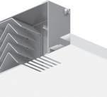
Profilo dissipante per Strip LED in lega di alluminio anodizzata naturale, testate di chiusura in polimero termoplastico, schermo diffusore ad inserimento a scatto in PMMA opale.
Schermo diffusore, testate di chiusura e n°4 staffe di fissaggio inclusi.
Strip LED e alimentatore 24Vdc da ordinare a parte.
Non esporre a intemperie o luce solare diretta e non inserire in materiale isolante.
Dissipating profile for Strip LED made of anodized aluminium alloy natural finish, end caps made of thermoplastic polymer, screen made of opal finish PMMA.
Diffuser, end caps and n°4 fixing brackets included.
Strip LED and driver 24Vdc to be ordered separately.
Do not expose to bad weather or direct sunlight and do not insert into insulating material.
CODE L (mm) Diffuser
105411.96 2000 Opale / Opal
CODE 105413.99 Acciaio / Steel
CODE 105412.99 Grigio chiaro / Light gray
CODE L (mm) 1018A2.99 6000 Opale / Opal
10 13 L 38,4
4 SMD 2216 (182 LED/m)
Biadesivo - sezionabile ogni 38,4 mm (7 LED)
9
Biadhesive - cuttable every 38,4 mm (7 LED) L
IP 40
CODE L (mm) LED COLOUR FLUX/m IP CRI 100913.99 5000 2700K 1100 20 90 100914.99 5000 3000K 1014 20 90 100915.99 5000 4000K 1154 20 90 100928.99 5000 2700K 1016 65 90 100929.99 5000 3000K 1038 65 90 100930.99 5000 4000K 1124 65 90 PROFILED MICRO STRIP LED 4mm 11,5 W/m 55 CEILING / WALL / FLOOR PROFILED
PROFILED
Profilo dissipante per Strip LED in lega di alluminio anodizzato naturale o verniciata bianca, testate di chiusura in polimero termoplastico, schermo diffusore ad inserimento a scatto in PMMA trasparente o opale.
Schermo diffusore, testate di chiusura e n°4 staffe di fissaggio inclusi.
Strip LED e alimentatore 24Vdc da ordinare a parte.
Non esporre a intemperie o luce solare diretta e non inserire in materiale isolante.
Dissipating profile for Strip LED made of anodized aluminium alloy, natural finish or white powder coated, end caps made of thermoplastic polymer, screen made of transparent or opal finish PMMA.
Diffuser, end caps and n°4 fixing brackets included.
Strip LED and driver 24Vdc to be ordered separately.
Do not expose to bad weather or direct sunlight and do not insert into insulating material.
CODE L (mm) Diffuser
15201._ _ 01 96 2000 Opale / Opal
15202._ _ 01 96 2000 Traspar. / Transp.
PROFILED H9
ACCESSORI ACCESSORIES
STAFFE DI FISSAGGIO (2 pz.)
Da prevedere in caso di utilizzo di sezioni di profilo tagliate in opera.
FIXING BRACKETS (2 pcs)
To be used for sections of profile cut on site.
TESTATE DI CHIUSURA (2 pz.)
Da prevedere in caso di utilizzo di sezioni di profilo tagliate in opera.
END CAPS ( 2pcs)
To be used for sections of profile cut on site.
SCHERMO OPALE 6 m
opzionale
Consigliato per installazioni in fila continua
OPAL SCREEN 6 m
optional
Recommended for continuous line installations
CODE
15213.99 Acciaio / Steel
15213.00 Trasparente / Transparent
CODE 15206. 01 99
CODE L (mm)
1018A3.99 6000 Opale / Opal
STRIP LED Pag. 80
Per ottenere uniformità di luminanza nelle installazioni con schermo a vista, utilizzare strip LED 19,2W/m, 22W/m, 8,8W/m (24Vdc), o 17W/m (48Vdc).
To achieve luminance uniformity when installed with clearly visible diffusors, the strip LED to be used is 19,2W/m, 22W/m, 8,8W/m (24Vdc), or 17W/m (48Vdc).
15 L L 17 9
H9
IP 40
56 CEILING / WALL / FLOOR
PROFILED H16
PROFILED H16
ACCESSORI ACCESSORIES
STAFFE DI FISSAGGIO (2 pz.)
Da prevedere in caso di utilizzo di sezioni di profilo tagliate in opera.
FIXING BRACKETS (2 pcs)
To be used for sections of profile cut on site.
TESTATE DI CHIUSURA (2 pz.)
Da prevedere in caso di utilizzo di sezioni di profilo tagliate in opera.
END CAPS ( 2pcs)
To be used for sections of profile cut on site.
Profilo dissipante per Strip LED in lega di alluminio anodizzata naturale, testate di chiusura in polimero termoplastico, schermo diffusore ad inserimento a scatto in PMMA opale.
Schermo diffusore, testate di chiusura e n°4 staffe di fissaggio inclusi.
Strip LED e alimentatore 24Vdc da ordinare a parte.
Non esporre a intemperie o luce solare diretta e non inserire in materiale isolante.
Dissipating profile for Strip LED made of anodized aluminium alloy natural finish, end caps made of thermoplastic polymer, screen made of opal finish PMMA.
Diffuser, end caps and n°4 fixing brackets included.
Strip LED and driver 24Vdc to be ordered separately.
Do not expose to bad weather or direct sunlight and do not insert into insulating material. CODE
SCHERMO OPALE 6 m
opzionale
Consigliato per installazioni in fila continua
OPAL SCREEN 6 m
optional
Recommended for continuous line installations
STRIP LED Pag. 80
Per ottenere uniformità di luminanza nelle installazioni con schermo a vista, utilizzare strip LED 19,2W/m, 22W/m, 8,8W/m (24Vdc), o 17W/m (48Vdc).
To achieve luminance uniformity when installed with clearly visible diffusors, the strip LED to be used is 19,2W/m, 22W/m, 8,8W/m (24Vdc), or 17W/m (48Vdc).
L 17 16 15 L IP 40
L (mm) Diffuser 16301.96 2000 Opale / Opal
CODE 16302.99 CODE L (mm) 1018A3.99 6000 Opale / Opal CODE 15213.99 Acciaio / Steel 15213.00 Trasparente / Transparent
57 PROFILED CEILING / WALL / FLOOR
PROFILED INCASSO H12
PROFONDITÀ DEL PROFILO PARI ALLO SPESSORE DEL CARTONGESSO DA 12,5 mm CHE CONSENTE IL MONTAGGIO SENZA INTERVENIRE SULLA STRUTTURA PORTANTE DEL CONTROSOFFITTO.
THE DEPTH OF THE PROFILE IS EQUAL TO THE THICKNESS OF THE 12.5 mm PLASTERBOARD ALLOWING INSTALLATION WITHOUT AFFECTING THE SUPPORTING STRUCTURE OF THE SUSPENDED CEILING.
Profilo dissipante per Strip LED in lega di alluminio anodizzata naturale o verniciata bianca, testate di chiusura in polimero termoplastico, schermo diffusore ad inserimento a scatto in PMMA opale.
Schermo diffusore, testate di chiusura e n°2 molle di fissaggio scorrevoli sul profilo inclusi, Strip LED e alimentatore 24Vdc da ordinare a parte.
Idoneo per controsoffitto di spessore max. 15 mm.
Non esporre a intemperie o luce solare diretta e non inserire in materiale isolante.
Dissipating profile for Strip LED made of anodized aluminium alloy, natural finish or white powder coated, end caps made of thermoplastic polymer, screen made of opal finish PMMA.
Diffuser, end caps and n°2 sliding fixing springs included.
Strip LED and driver 24Vdc to be ordered separately. Suitable for ceiling thickness max. 15 mm.
Do not expose to bad weather or direct sunlight and do not insert into insulating material.
PROFILED INCASSO H12
ACCESSORI ACCESSORIES
MOLLE DI FISSAGGIO (2 pz.)
Da prevedere in caso di utilizzo di sezioni di profilo tagliate in opera.
FIXING SPRINGS (2 pcs)
To be used for sections of profile cut on site.
TESTATE DI CHIUSURA (2 pz.)
Da prevedere in caso di utilizzo di sezioni di profilo tagliate in opera.
END CAPS ( 2pcs)
To be used for sections of profile cut on site.
SCHERMO OPALE 6 m opzionale
Consigliato per installazioni in fila continua
OPAL SCREEN 6 m optional
Recommended for continuous line installations
STRIP LED Pag. 80
Per ottenere uniformità di luminanza nelle installazioni con schermo a vista, utilizzare strip LED 19,2W/m, 22W/m, 8,8W/m (24Vdc), o 17W/m (48Vdc).
To achieve luminance uniformity when installed with clearly visible diffusors, the strip LED to be used is19,2W/m, 22W/m, 8,8W/m (24Vdc), or 17W/m (48Vdc).
15 L L 12,2 27 12,5 H 65 L Ltot W 20 62 25 12,5 L 12,2 27 12,5 H 65 L Ltot W 20 62 25 12,5
CODE L (mm) 1018A3.99 6000 Opale / Opal
IP 40 CODE L (mm) Diffuser 105415. 01 96 2000 Opale / Opal CODE 105417. 01 99 CODE 105419.99 Acciaio / Steel
58 CEILING / WALL / FLOOR
PROFILED
AD ANGOLO H16
Profilo dissipante per Strip LED in lega di alluminio anodizzata naturale o verniciata bianca , testate di chiusura in polimero termoplastico, schermo diffusore ad inserimento a scatto in PMMA opale.
Schermo diffusore, testate di chiusura e n°4 staffe di fissaggio inclusi.
Strip LED e alimentatore 24Vdc da ordinare a parte.
Non esporre a intemperie o luce solare diretta e non inserire in materiale isolante.
Dissipating profile for Strip LED made of anodized aluminium alloy natural finish or white powder coated, end caps made of thermoplastic polymer, screen made of opal finish PMMA.
Diffuser, end caps and n°4 fixing brackets included.
Strip LED and driver 24Vdc to be ordered separately.
Do not expose to bad weather or direct sunlight and do not insert into insulating material.
CODE L (mm) Diffuser 105408. 01 96 2000 Opale / Opal
PROFILED
AD
ANGOLO H16
ACCESSORI ACCESSORIES
STAFFE DI FISSAGGIO (2 pz.)
Da prevedere in caso di utilizzo di sezioni di profilo tagliate in opera.
FIXING BRACKETS (2 pcs)
To be used for sections of profile cut on site.
TESTATE DI CHIUSURA (2 pz.)
Da prevedere in caso di utilizzo di sezioni di profilo tagliate in opera.
END CAPS ( 2pcs)
To be used for sections of profile cut on site.
STRIP LED
Pag. 80
Per ottenere uniformità di luminanza nelle installazioni con schermo a vista, utilizzare strip LED 19,2W/m, 22W/m, 8,8W/m (24Vdc), o 17W/m (48Vdc).
To achieve luminance uniformity when installed with clearly visible diffusors, the strip LED to be used is 19,2W/m, 22W/m, 8,8W/m (24Vdc), or 17W/m (48Vdc).
CODE 105410.99 Acciaio / Steel
CODE 105409. 01 96
L 16 16
IP 40
59 PROFILED CEILING / WALL / FLOOR
PROFILED 230
Profilo dissipante per Strip LED in lega di alluminio anodizzata naturale, testate di chiusura in polimero termoplastico, schermo diffusore ad inserimento a scatto in policarbonato opale. Schermo diffusore, testate di chiusura e n°4 staffe di fissaggio inclusi. Idoneo per Strip LED 230V/24V/48V. Strip LED ed eventuale alimentatore da ordinare a parte. Non esporre a intemperie o luce solare diretta e non inseire in materiale isolante.
Dissipating profile for LED strip made of anodized aluminium alloy natural finish, end caps made of thermoplastic polymer, screen made of opal PMMA. Diffuser, end caps and n°4 fixing brackets included. Suitable for LED strip 230V/24V/48V. Strip LED and any driver to be ordered separately. Do not expose to bad weather or direct sunlight and do not insert into insulating material.
CODE L (mm) Diffuser 105424.96 2000 Opale / Opal
PROFILED 230
ACCESSORI ACCESSORIES
TESTATE DI CHIUSURA (2pz)
Da prevedere in caso di utilizzo di sezioni di profilo tagliate in opera.
END CAPS (2pcs)
To be used for sections of profile cut on site.
STAFFE DI FISSAGGIO (2pz)
Da prevedere in caso di utilizzo di sezioni di profilo tagliate in opera.
FIXING BRACKETS (2pcs)
To be used for sections of profile cut on site.
CODE 105425.99
CODE 105426.99
19 13 L
IP 40
NEW 60 CEILING / WALL / FLOOR
STRIP LED 230V
STRIP LED 230V 9,4 W/m
SMD 2835 (84 LED/m)
Biadesivo - sezionabile
ogni 165mm (14 LED)
SMD 2835 (84 LED/m)
Bihadesive - cuttable every 165mm (14 LED)
STRIP LED 230V 18 W/m
SMD 2835 (140 LED/m)
Biadesivo - sezionabile ogni 200mm (28 LED)
SMD 2835 (140 LED/m)
Bihadesive - cuttable every 200mm (28 LED)
STRIP LED 230V
ACCESSORI ACCESSORIES
KIT PER RIPRISTINO PROTEZIONE IP65
N°2 testate terminali (1 con foro, 1 di chiusura), fusibile e cavo 2x0,75 mm2 L= 300 mm.
Da prevedere in caso di utilizzo di sezione di strip LED tagliata in opera. Sigillante siliconico obbligatorio da ordinare a parte.
IP65 PROTECTION RESTORATION KIT
N°2 end caps (1 with hole, 1 locking), fuse and cable 2x0,75 mm2 L= 300 mm. To be provided in case of use of LED strip section cut in place. Mandatory silicone sealant to be ordered separately.
SIGILLANTE SILICONICO
Tubo da 60 ml di silicone acetico trasparente resistente UV
SILICONE SEALANT 60 ml tube of UV resistant transparent acetic silicone
KIT DI INSTALLAZIONE
N° 10 clips siliconiche + n°20 viti
Idoneo per 5m di StripLED 230V
INSTALLATION KIT
N° 10 silicone clips + n° 20 screws
Suitable for 5m StripLED 230V
CODE LED COLOUR POWER FLUX/m L (mm) IP CRI 100956.99 3000K 9,4W/m 1088 5m 65 80 100957.99 4000K 9,4W/m 1144 5m 65 80 100958.99 3000K 9,4W/m 1088 50m 65 80 100959.99 4000K 9,4W/m 1144 50m 65 80 CODE LED COLOUR POWER FLUX/m L (mm) IP CRI 100960.99 3000K 18W/m 2051 5m 65 80 100961.99 4000K 18W/m 2158 5m 65 80 100962.99 3000K 18W/m 2051 50m 65 80 100963.99 4000K 18W/m 2158 50m 65 80 5 165 12 1000 5 200 12 1000
CODE
CODE 100966.99 CODE 100964.99 14 7 15 8 300 x10 14 7 15 8 300 61 PROFILED CEILING / WALL / FLOOR
100965.99
62
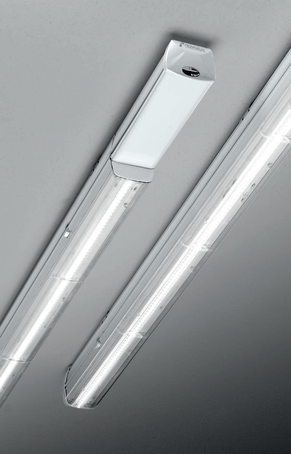
Apparecchio LED lineare per installazione in fila continua. Modulo Femmina-Maschio (F/M), Modulo LED e Modulo terminale in lamiera di acciaio verniciata, modulo cieco e testate in termoplastico e lenti in PMMA. Moduli F/M con cablaggio passante a 8 poli per la continuità di linea e connessione rapida dell’alimentazione in 2 configurazioni: 3 fasi selezionabili+T+linea emergenza oppure 1 fase+T+linea emergenza+BUS DALI. Moduli LED con alimentazione elettronica 220-240V 50/60 Hz integrata, on/off o DALI. Disponibili versioni in emergenza a servizio continuo 1 ora sia per moduli on/off che DALI.
Linear LED fixture for series system installation.
F/M Module, LED Module and End line Module made of painted sheet steel, empty module and caps in thermoplastc and lens in PMMA. F/M Modules with wiring through for line continuity and quick connection of power supply in 2 options: 3 sectable phases+PE+emergency line or 1 phase+PE+emergency line+BUS DALI.
Led Modules with integrated 240V 50/60 Hz power supply, on/off or DALI. Emergency versions available for continuous service 1 hour, for both on/ off and DALI modules.
MODULO F/M 8 POLI
Connettori per innesto rapido inclusi. Modulo LED, Kit di alimentazione,Testata inizio linea, Modulo terminale ed accessori per l’installazione da ordinare a parte.
F/M 8 POLES MODULE
Rapid connectors included. LED module, Power supply, Start line cap, End line module and accessory for installation to be ordered separately.
MODULO LED 90°
Per installazione su Modulo F/M, da ordinare a parte.
90° LED MODULE
For F/M module, to be ordered separately.
Autonomia 1h / Ricarica 12h
Autonomy 1h / Charging 12h
Autonomia 1h / Ricarica 12h
Autonomy 1h / Charging 12h
MODULO LED BATWING
Per installazione su Modulo F/M, da ordinare a parte.
BATWING LED MODULE
For F/M module, to be ordered separately.
Autonomia 1h / Ricarica 12h
Autonomy 1h / Charging 12h
Autonomia 1h / Ricarica 12h
Autonomy 1h / Charging 12h
Flusso in emergenza / Emergency flux 11%
in emergenza / Emergency flux 11%
in emergenza / Emergency flux 11%
DALI + EMERGENCY
in emergenza / Emergency flux 11%
C.A.M. Edilizia L 40 70 L 40 70 L 40 70
IP 40 L (mm) 1500 107212.01 POWER L (mm) FLUX 46W1500 7627 lm 107213.01 DALI POWER L (mm) FLUX 46W1500 7627 lm 107215.01 EMERGENCY
POWER L (mm) FLUX 46W1500 7627 lm 107217.01 DALI
Flusso
POWER L (mm) FLUX 46W1500 7627 lm 107219.01 POWER L
FLUX 46W1500 7491 lm 107214.01 DALI POWER L (mm) FLUX 46W1500 7491 lm 107216.01 EMERGENCY
POWER L (mm) FLUX 46W1500 7491 lm 107218.01
POWER
FLUX 46W1500 7491 lm 107220.01
+ EMERGENCY
(mm)
Flusso
Flusso
L (mm)
220-240V 50/60Hz RISCHIO GRUPPO 0 DESIGNED IN ITALY
LI-NEAR
NEW NEW 63 CEILING / WALL / FLOOR LI-NEAR NEW
MODULO BINARIO
Per installazione su Modulo F/M, da ordinare a parte.
TRACK MODULE
For F/M module, to be ordered separately.
MODULO CON SENSORE DI PRESENZA E LUMINOSITA’
Per installazione su modulo F/M da ordinare a parte. Completo di sensore DALI integrato nella cover. Da gestire tramite centralina DALI LIGHT IOT o DALI PROFESSIONAL, da ordinare a parte.
MODULE WITH PRESENCE
DETECTOR AND LIGHT SENSOR
For installation on F/M module,to be ordered separately. Complete with DALI sensor integrated in the cover. To be managed via DALI LIGHT IOT or DALI PROFESSIONAL control unit, to be ordered separately.
Per installazione su Modulo F/M, da ordinare a parte.
EMPTY MODULE
For F/M module, to be ordered separately.
MODULO TERMINALE
Non elettrificato, completo di testata. Da installare come chiusura su Modulo F/M di fine fila continua. END
Not wired, cap included. To be installed as closure on F/M Module of end line.
L 50 70 20 70 L MODULO CIECO
LINE MODULE
L (mm) 220 107204.01 L (mm) 1500 107206.01
IP 20 L (mm) TRACK 1500 Trifase/Three-phase 107221.01 DALI L (mm) TRACK 1500 Monofase/Mono-phase 107222.01 DALI L (mm) 1500 107223.01 20 70 L NEW NEW 20 70 L 64 CEILING / WALL / FLOOR
MODULO CIECO A L Non alimentabile. Prevedere un kit di sospensione o una staffa per installazione a plafone.
L BLIND MODULE Without plug-in. Provide one suspension kit or one ceiling mounting accessory.
Vista dall’alto / Top view
Vista dall’alto / Top view
Configurazione standard Standard configuration
Configurazione standard Standard configuration
Configurazione modificabile in opera Configuration that can be modified on site
Configurazione modificabile in opera Configuration that can be modified on site
MODULO CIECO A T Non alimentabile. Prevedere un kit di sospensione o una staffa per installazione a plafone.
T BLIND MODULE Without plug-in. Provide one suspension kit or one ceiling mounting accessory.
Vista dall’alto / Top view
Vista dall’alto / Top view
Configurazione standard Standard configuration
Configurazione standard Standard configuration
Configurazione A modificabile in opera Configuration A that can be modified on site
Configurazione A modificabile in opera Configuration A that can be modified on site
Configurazione B modificabile in opera Configuration B that can be modified on site
Configurazione B modificabile in opera Configuration B that can be modified on site
L (mm) 285x285 107224.01 L (mm) 500x285 107225.01 50 285 285 70 50 500 285 70 NEW NEW F M M F M M F M M M F F M
F M M F M M F M M M F F M
Start line cap 107205.01 Power supply kit 107226.99 L blind module 107224.01 T blind module 107225.01 Track module 107221.01 Linear blind module 107206.01 End line module 107204.01 LED module 107213.01/ 107214.01 F/M 8 poles module 107212.01 Suspension kit 107207.99
mounting bracket 107209.99 65 CEILING / WALL / FLOOR LI-NEAR
Ceiling
LI-NEAR ACCESSORI ACCESSORIES
KIT DI ALIMENTAZIONE
Connessione rapida di alimentazione a 8 poli, per Modulo F/M di inizio linea.
POWER SUPPLY KIT
8 poles rapid connection, for start line F/M Module
TESTATE INIZIO LINEA (2 pz.)
Da installare ad inizio fila continua.
START LINE CAPS (2 pcs)
To be installed at start line system.
KIT DI SOSPENSIONE (1 pz.)
Completo di tassello ad espansione con gancio. Prevedere 2pz per ciascun modulo lineare e 1pz per ciascun modulo cieco L e T.
SUSPENSION KIT (1 pc)
Complete with expansion plug with hook. Provide 2pcs for each linear module and 1pc for each L and T blind module.
STAFFA PER INSTALLAZIONE
A PLAFONE (2 pz.)
Prevedere 2pz per ciascun modulo lineare e 1pz per ciascun modulo cieco L e T.
CEILING MOUNTING
ACCESSORY (2 pcs)
Provide 2pcs for each linear module and 1pc for each L and T blind module.
25 12 12 L 25
CODE L (mm) 107207.99 3000 CODE 107209.99 20 78 72
CODE 107205.01
CODE 107226.99 66 CEILING / WALL / FLOOR
67 CEILING / WALL / FLOOR LI-NEAR
68
TRACK
70
Apparecchio lineare per installazione a binario elettrificato trifase a 7 poli All-Track. (Non idoneo per binario ad incasso). Potenza settabile tramite selettore. Ottica a lenti lineari in PMMA ad emissione diffusa 90°, corpo in acciaio verniciato a polvere bianca. Alimentazione elettronica dimmerabile DALI 220-240V 50/60 Hz, integrata nell’adattatore.
Linear LED fixture for installation on 7-pole three-phase electrified All-Track. (Not suitable for recessed track). Selectable LED power. PMMA linear lenses optics with diffuse emission 90°, white powder coated steel body. Electronic power supply dimmable DALI 220-240V 50/60 Hz, integrated in the adapter.
DALI POWER L (mm) FLUX 3000K 4000K 35W / 40W / 45W / 50W 1500 Variable* 110401.01 110402.01 CRI >90 IP 20 RISCHIO FOTOBIOLOGICO GRUPPO 1 SHOW 12 L 62 LED colour FLUX / POWER 35W 40W 45W 50W 3000K 4515 / 5160 / 5805 / 6450 lm 4000K 4620 / 5280 / 5940 / 6600 lm
Potenza selezionabile con selettore Selectable LED power
Selettore della potenza Power selection
di
knob CLACK 50W 45W 40W 35W ALL-TRACK Selettore della potenza Power selection
di fissaggio
idoneo per All-Track incasso - Not suitable for All-Track recessed 71 SHOW TRACK
*
C.A.M. Edilizia
Leva
fissaggio Adaptor
Leva
Adaptor knob Non
72
ALL-TRACK PLAFONE-SOSPENSIONE CEILING-SUSPENSION
BINARIO ELETTRIFICATO TRIFASE 7 POLI
ELECTRIFIED THREE-PHASE 7 POLES TRACK
Binario elettrificato trifase 7 poli con due conduttori dedicati D+, D- per la gestione della dimmerazione. Profilo in lega di alluminio verniciata contenente i conduttori in rame. Compatibile con Lucky Evo, Show e proiettori Dalì e Gala (on-off e DALI).
L1/L2/L3/N/Terra (16A 230V) e D+/D-(segnale DALI, 0-10V, 1-10V).
Non utilizzabile comando di dimmerazione a pulsante a 230V.
La funzione PUSH è ammessa solo con interposizione di interfaccia pulsante con uscita DALI (cod. 18908.99 oppure 18906.99).
Three-phase electrified track with 7 poles with two dedicated conductors D+, D- for dimming management. Painted aluminium alloy profile containing copper conductors. Compatible with Lucky Evo, Show and Dalì and Gala projectors (on-off and DALI). L1/L2/L3/N/PE (16A 230V) and D+/D-(DALI signal, 0-10V, 1-10V).
230V push-button dimming control not available. The PUSH function is only allowed with button interface interposition with DALI output. (cod. 18908.99 or 18906.99).
PER FUNZIONE PUSH PREVEDERE INTERFACCIA PULSANTE CON USCITA DALI 18908.99 O 18906.99. VEDI SEZIONE GESTIONE LUCE.
FOR PUSH FUNCTION PROVIDE INTERFACE BUTTON WITH DALI OUTPUT 18908.99 OR 18906.99. SEE LIGHT MANAGEMENT SECTION.
ACCESSORI ACCESSORIES
ALIMENTAZIONE CENTRALE E GIUNTO LINEARE CENTRAL FEED JOINT
ALIMENTAZIONE DI TESTA START LIVE END
GIUNTO LINEARE ELETTRIFICATO
ELECTRIFIED STRAIGHT JOINT
CHIUSURA TERMINALE DEAD END
GIUNTO a X
X JOINT
GIUNTO a T
T JOINT
GIUNTO a L
L JOINT
99 88 106 99 99 68 68 L 35 32,5 L1 L2 D- D+ N L3 ALL-TRACK L 35 32,5 L1 L2 D- D+ N L3 CODE 106704.01 .02 CODE 106709.01 .02 CODE 106707.01 .02 CODE 106708.01 .02 CODE VERSION 106705.01 .02 destra / right 106706.01 .02 sinistra / left CODE VERSION 106710.01 .02 interno sinistro / inside left 106711.01 .02 interno destro / inside right 106712.01 .02 esterno sinistro / outside left 106713.01 .02 esterno destro / outside right CODE VERSION 106714.01 .02 interno / inside 106715.01 .02 esterno / outside CODE L (mm) 106701.01 .02 1000 106702.01 .02 2000 106703.01 .02 3000
IP 20
0-10V 1-10V
73 ALL-TRACK TRACK
GIUNTO SNODATO Non alimentabile.
ADJUSTABLE JUNCTION without feeding.
STAFFA DI FISSAGGIO A PARETE (1pz) Vedere schema dei carichi per la quantità di staffe.
WALL MOUNTING BRACKET (1pc) See load scheme for quantity.
STAFFA DI FISSAGGIO A PLAFONE (1 pz.) Vedere schema dei carichi per
BRACKET FOR CEILING MOUNTING (1 pc) See load scheme for quantity.
ADATTATORE MECCANICO/ELETTRICO NON CABLATO 6A (1 pz.) carico massimo 10 kg
KIT DI SOSPENSIONE (2 pz.) Vedere schema dei carichi per la quantità di sospensioni.
SUSPENSION KIT (2 pcs) See load scheme for quantity.
TRACK 40 85 113 L 40 ø12 17 ALL-TRACK 80 92 25 74 80 92 25 74 50 185
la quantità di staffe.
CODE VERSION 106718.01 .02 3P 106719.01 .02 3P+DALI CODE 106717.01 .02 CODE 106724.01 .02 CODE 106728.01 .02 CODE L (mm) 106721.01 .02 3000
MECHANICAL/ELECTRIC NOT
(1 pc) maximum load 10 kg
3P 3P+DALI 106709_ 106710_ 106711 106712 106713 106714_ 106715_106704_ 106716_ 106708 106705 106708_ 106706_ 106707_ ALL-TRACK Polarità Polarity Vista dall’alto Top view 100 200 200 200 200 100 1000 5 kg 5 kg 5 kg 5 kg 5 kg Carico m assim o Maximum load Polarità Polarity Carico massimo Maximum load Vista dall’alto Top view 80 240° 80 95 95 80 240° 80 95 95 GIUNTO FLESSIBILE
alimentabile FLEXIBLE
JOINT without feeding CODE 106716.01 .02 74
WIRED ADAPTOR 6A
ACCESSORI ACCESSORIES
non
FEED
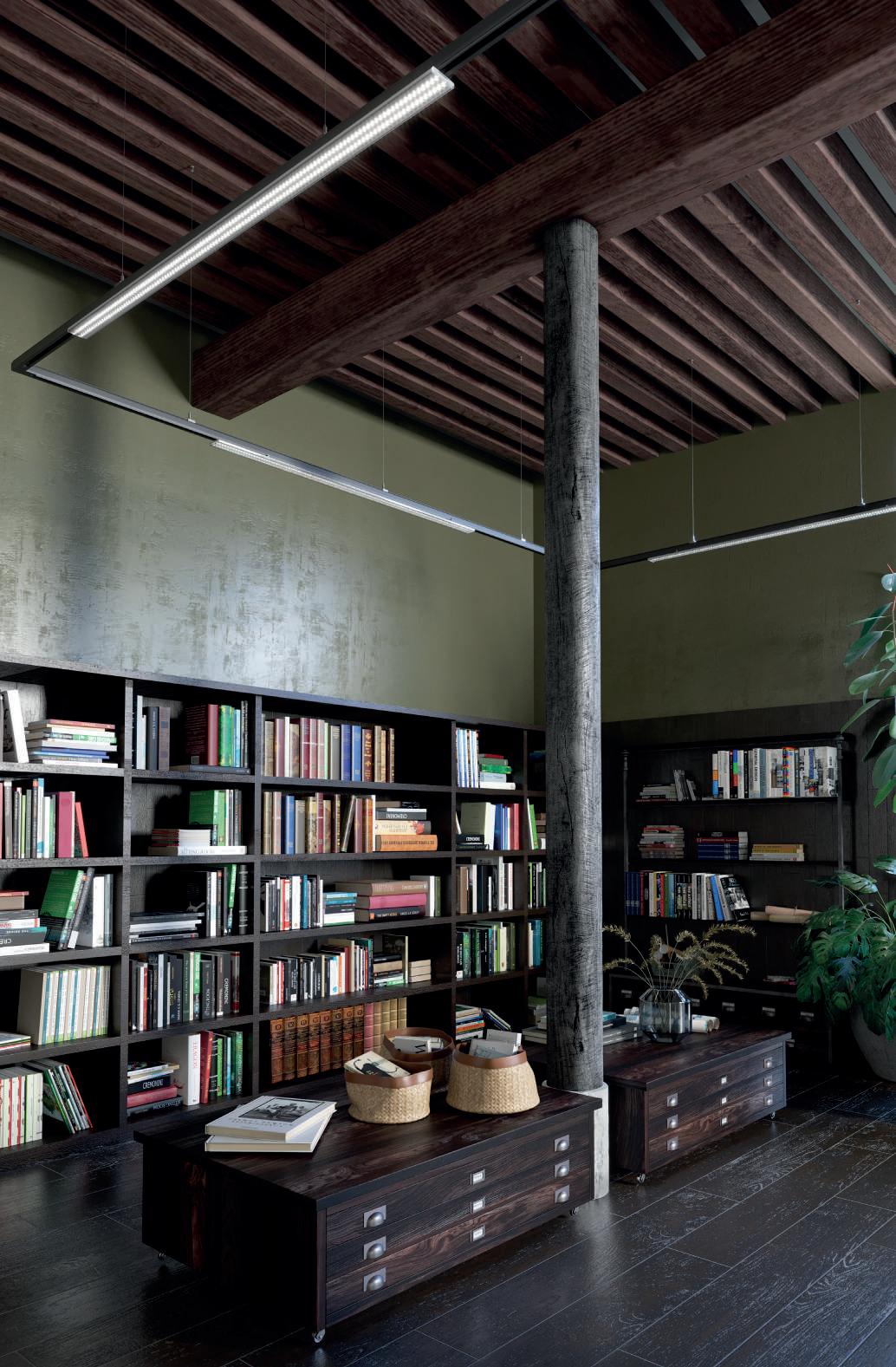
TRACK 75 ALL-TRACK
ALL-TRACK INCASSO/RECESSED
Binario elettrificato trifase 7 poli con due conduttori dedicati D+, D- per la gestione della dimmerazione. Profilo in lega di alluminio verniciata contenente i conduttori in rame.
Compatibile con Lucky Evo e proiettori Dalì e Gala (on-off e DALI).
L1/L2/L3/N/Terra (16A 230V) e D+/D-(segnale DALI, 0-10V, 1-10V). Non utilizzabile comando di dimmerazione a pulsante a 230V.
La funzione PUSH è ammessa solo con interposizione di interfaccia pulsante con uscita DALI (cod. 18908.99 oppure 18906.99).
Three-phase electrified track with 7 poles with two dedicated conductors D+, D- for dimming management. Painted aluminium alloy profile containing copper conductors. Compatible with Lucky Evo and Dalì and Gala projectors (on-off and DALI).
L1/L2/L3/N/PE (16A 230V) and D+/D-(DALI signal, 0-10V, 1-10V).
230V push-button dimming control not available. The PUSH function is only allowed with button interface interposition with DALI output. (cod. 18908.99 or 18906.99).
BINARIO ELETTRIFICATO DA INCASSO TRIFASE 7
PER FUNZIONE PUSH PREVEDERE INTERFACCIA PULSANTE CON USCITA DALI 18908.99 O 18906.99. VEDI SEZIONE GESTIONE LUCE. FOR PUSH FUNCTION PROVIDE INTERFACE BUTTON WITH DALI OUTPUT 18908.99 OR 18906.99. SEE LIGHT MANAGEMENT SECTION.
TRACK
CODE L (mm) 106725.01 1000 106726.01 2000 106727.01 3000
POLI
POLES TRACK
RECESSED MOUNTING IP 20 0-10V 1-10V
ELECTRIFIED THREE-PHASE 7
FOR
99 CODE 106704.01 CODE 106730.01 ALIMENTAZIONE CENTRALE E GIUNTO LINEARE Cover da ordinare a parte CENTRAL FEED JOINT Cover to be ordered separately COVER PER ALIMENTAZIONE CENTRALE Alimentazione centrale da ordinare a parte COVER FOR CENTRAL FEED JOINT Central feed joint to be ordered separately 99 56 ALL-TRACK INCASSO/RECESSED ACCESSORI ACCESSORIES 88 CODE VERSION 106705.01 destra / right 106706.01 sinistra / left CODE 106729.01 ALIMENTAZIONE DI TESTA Cover da ordinare a parte START LIVE END Cover to be ordered separately COVER PER ALIMENTAZIONE DI TESTA Alimentazione di testa da ordinare a parte COVER FOR START LIVE END Start live end to be ordered separately 89 56 106 CODE 106707.01 CODE 106734.01 GIUNTO LINEARE ELETTRIFICATO ELECTRIFIED STRAIGHT JOINT CHIUSURA TERMINALE DEAD END 20
35 56 30 L L1 DN L2 D+ L3 L W Ltot 40 2,5 76
ACCESSORI ACCESSORIES
GIUNTO A X
Cover da ordinare a parte
X JOINT
Cover to be ordered separately
COVER PER GIUNTO a X Giunto a X da ordinare a parte
COVER FOR X JOINT X joint to be ordered separately
GIUNTO a T Cover da ordinare a parte T JOINT Cover to be ordered separately
COVER PER GIUNTO a T Giunto a T da ordinare a parte
COVER FOR T JOINT T joint to be ordered separately
GIUNTO a L
Cover da ordinare a parte L JOINT Cover to be ordered separately
COVER PER GIUNTO a L Giunto a L da ordinare a parte COVER FOR L JOINT L joint to be ordered separately
ADATTATORE MECCANICO/ ELETTRICO NON CABLATO 6A
pz.) carico massimo 10 kg
pc) maximum load 10 kg
DI SOSPENSIONE (2pz) Vedere schema dei carichi per la quantità di sospensioni
KIT (2pcs) See load scheme for quantity
TRACK
INCASSO/RECESSED
ALL-TRACK
CODE 106709.01 CODE 106733.01 CODE 106732.01
99 56 99 99 68 CODE VERSION 106710.01
106711.01
106712.01
106713.01
68 CODE VERSION 106714.01 interno
106715.01 esterno
CODE 106731.01
interno sinistro / inside left
interno destro / inside right
esterno sinistro / outside left
esterno destro / outside right
/ inside
/ outside
85 113 CODE VERSION 106718.01 3P 106719.01 3P+DALI
MECHANICAL/ELECTRIC
(1
3P 3P+DALI L 40 ø12 17 KIT
SUSPENSION
CODE L (mm) 106721.01 3000 100 200 200 200 200 100 1000 5 kg 5 kg 5 kg 5 kg 5 kg Carico m assim o Maximum load 106709.01+ 106733.01 106710.01+ 106732.01 106711.01+ 106732.01 106712.01+ 106732.01 106713.01+ 106732.01 106714.01+ 106731.01 106715.01+ 106731.01 106704.01+ 106730.01 106734.01 106705.01+ 106729.01 106734.01 106706.01+ 106729.01 106707.01 ALL-TRACK INCASSO Polarità Polarity Vista dall’alto Top view Polarità Polarity Carico massimo Maximum load Vista dall’alto Top view 77 77 56 56 77 99 77 ALL-TRACK
(1
NOT WIRED ADAPTOR 6A
78
STRIP
LED AND LIGHT MANAGEMENT
STRIP LED 24V
LE GARANZIE PRODOTTO SARANNO APPLICABILI, PER RAGIONI DI SICUREZZA E FRUIBILITÀ, SOLO UTILIZZANDO PROFILI DISSIPANTI A CATALOGO ED ALIMENTAZIONI NOVALUX. THE PRODUCT WARRANTY CONDITIONS WILL APPLY, DUE TO REASONS OF SAFETY AND QUALITY OF USE, ONLY WHEN INSTALLED WITH DISSIPATING PROFILES AND DRIVERS FROM NOVALUX CATALOGUES.
STRIP LED 19,2W/m
SMD 2835 (238 LED/m)
Biadesivo - sezionabile ogni 29,4 mm (7 LED)
Strip LED idonea per ottenere uniformità di luminanza nelle installazioni con schermo a vista
Bihadesive - cuttable every 29,4 mm (7 LED)
29,4 10
Strip LED suitable to achieve luminance uniformity, when installed with clearly visible diffusors
STRIP LED 22W/m
SMD 2835 (238 LED/m)
Biadesivo - sezionabile ogni 29,4 mm (7 LED)
Strip LED idonea per ottenere uniformità di luminanza nelle installazioni con schermo a vista
Bihadesive - cuttable every 29,4 mm (7 LED)
29,4 10
Strip LED suitable to achieve luminance uniformity, when installed with clearly visible diffusors
STRIP LED 8,8W/m
2835 (240 LED/m)
- sezionabile ogni 25 mm (6 LED)
Strip LED idonea per ottenere uniformità di luminanza nelle installazioni con schermo a vista
Bihadesive - cuttable every 25 mm (6 LED)
Strip LED suitable to achieve luminance uniformity, when installed with clearly visible diffusors
STRIP LED 14,4W/m SMD 2835 (140 LED/m)
Biadesivo - sezionabile ogni 50 mm (7 LED)
Bihadesive - cuttable every 50 mm (7 LED)
PCB flessibile con biadesivo sul lato posteriore, versioni IP65 con rivestimento in silicone flessibile. Alimentazione elettronica o dimmerabile 24V, da ordinare a parte.
Vedere sezione GESTIONE LUCE per sistemi di controllo STRIP LED.
Flexible PCB and double-sided back adhesive, flexible silicon coating for IP65 version. Electronic or dimmable driver 24V to be ordered separately. See section LIGHT MANAGEMENT for other strip LED components.
STRIP LED 16,5W/m
SMD 2835 (140 LED/m)
Biadesivo - sezionabile ogni 50 mm (7 LED)
Bihadesive - cuttable every 50 mm (7 LED)
STRIP LED 11,5W/m
SMD 2835 (126 LED/m)
Biadesivo - sezionabile ogni 55,5 mm (7 LED)
Bihadesive - cuttable every 55,5 mm (7 LED)
RISCHIO FOTOBIOLOGICO GRUPPO 1 SMD 2835 (126 LED/m) Biadesivo - sezionabile ogni 55,5 mm (7 LED) Biadhesive - cuttable every 55,5 mm (7 LED) 55,5 10 CODE LED COLOUR POWER FLUX/m L (mm) IP CRI 100938.99 2700K 19,2W/m 1952 5000 20 90 100939.99 3000K 19,2W/m 2140 5000 20 90 100940.99 4000K 19,2W/m 2176 5000 20 90 100934.99 3000K 19,2W/m 2402 5000 20 80 100935.99 4000K 19,2W/m 2452 5000 20 80 100936.99 3000K 19,2W/m 2050 5000 65 80 100937.99 4000K 19,2W/m 2244 5000 65 80
CODE LED COLOUR POWER FLUX/m L (mm) IP CRI 100941.99 3000K 22W/m 2788 5000 20 80 100942.99 4000K 22W/m 2804 5000 20 80 100943.99 3000K 22W/m 2464 5000 65 80 100944.99 4000K 22W/m 2594 5000 65 80
CODE LED COLOUR POWER FLUX/m L (mm) IP CRI 100949.99 2700K 14,4W/m 1498 5000 20 90 100950.99 3000K 14,4W/m 1646 5000 20 90 100951.99 4000K 14,4W/m 1666 5000 20 90 100945.99 3000K 14,4W/m 1892 5000 20 80 100946.99 4000K 14,4W/m 1880 5000 20 80 100947.99 3000K 14,4W/m 1578 5000 65 80 100948.99 4000K 14,4W/m 1716 5000 65 80 50 10
SMD
Biadesivo
CODE LED COLOUR POWER FLUX/m L (mm) IP CRI 100922.99 2700K 8,8W/m 902 5000 20 90 100923.99 3000K 8,8W/m 844 5000 20 90 100924.99 4000K 8,8W/m 900 5000 20 90 25 10 SMD 2835 (240 LED/m) Biadesivo - sezionabile ogni 25 mm (6 LED) Biadhesive - cuttable every 25 mm (6 LED) CODE LED COLOUR POWER FLUX/m L (mm) IP CRI 100952.99 3000K 16,5W/m 1982 5000 20 80 100953.99 4000K 16,5W/m 2002 5000 20 80 100954.99 3000K 16,5W/m 1836 5000 65 80 100955.99 4000K 16,5W/m 1992 5000 65 80 50 10 CODE LED COLOUR POWER FLUX/m L (mm) IP CRI 100919.99 2700K 11,5W/m 1206 5000 20 90 100920.99 3000K 11,5W/m 1218 5000 20 90 100921.99 4000K 11,5W/m 1278 5000 20 90 CAVO DI ALIMENTAZIONE L.150mm INCLUSO, SU ENTRAMBE LE ESTREMITÀ DELLA BOBINA. POWER SUPPLY CABLE L.150mm INCLUDED, ON BOTH ENDS OF THE COIL. 80
STRIP LED 20,5W/m
SMD 5730 (112 LED/m)
Biadesivo - sezionabile
ogni 62,5 mm (7 LED)
Bihadesive - cuttable every 62,5 mm (7 LED)
STRIP LED 4mm 11,5W/m
SMD 2216 (182 LED/m)
Biadesivo - sezionabile
ogni 38,4 mm (7 LED)
Per profilo L-09 e Profiled MICRO
Bihadesive - cuttable every 38,4 mm (7 LED)
Suitable for L-09 profile and Profiled MICRO
- cuttable every 62,5 mm (7 LED)
STRIP LED DOPPIA PISTA 25W/m
STRIP LED DOUBLE LANE 25W/m
SMD 2835 (336 LED/m)
Biadesivo - sezionabile
ogni 41,6 mm (14 LED)
Per profilo L-33
e Profiled MACRO
Bihadesive - cuttable every 41,6 mm (14 LED)
Suitable for L-33 profile and Profiled MACRO
STRIP LED RGB 14,4W/m
SMD 5050 (60 LED/m)
Biadesivo - sezionabile ogni 100 mm (6 LED)
Bihadesive - cuttable every 100 mm (6 LED)
STRIP LED RGB+WHITE 14,4W/m
SMD 5050 (60 LED/m)
Biadesivo - sezionabile
ogni 167 mm (10 LED)
Bihadesive - cuttable every 167 mm (10 LED)
STRIP LED TUNABLE WHITE 19,2W/m
SMD 3528 (240 LED/m)
Biadesivo - sezionabile
ogni 50 mm (12 LED)
Per i componenti di gestione del bianco dinamico vedere la sezione
GESTIONE LUCE
Bihadesive - cuttable every 50 mm (12 LED)
See section LIGHT MANAGEMENT for the tunable white control components
STRIP LED 48V
LE GARANZIE PRODOTTO SARANNO APPLICABILI, PER RAGIONI DI SICUREZZA E FRUIBILITÀ, SOLO UTILIZZANDO PROFILI DISSIPANTI A CATALOGO ED ALIMENTAZIONI NOVALUX. THE PRODUCT WARRANTY CONDITIONS WILL APPLY, DUE TO REASONS OF SAFETY AND QUALITY OF USE, ONLY WHEN INSTALLED WITH DISSIPATING PROFILES AND DRIVERS FROM NOVALUX CATALOGUES.
PCB flessibile con biadesivo sul lato posteriore. Alimentazione 48V da ordinare a parte. Vedere sezione GESTIONE LUCE per sistemi di controllo strip LED.
Flexible PCB and double-sided back adhesive. 48V driver to be ordered separately. See section LIGHT MANAGEMENT for other strip LED components.
STRIP LED
RISCHIO FOTOBIOLOGICO GRUPPO 1 STRIP LED 17W/m SMD 2835 (240 LED/m) Biadesivo - sezionabile ogni 62,5 mm (15 LED) Bihadesive - cuttable every 62,5 mm (15 LED) CODE LED COLOUR POWER FLUX/m L (mm) IP CRI 100931.99 2700K 17W/m 2060 5000 20 90 100932.99 3000K 17W/m 2096 5000 20 90 100933.99 4000K 17W/m 2380 5000 20 90 62,5 10 38,4 4 SMD 2216 (182 LED/m) Biadesivo - sezionabile ogni 38,4 mm (7 LED) Biadhesive - cuttable every 38,4 mm (7 LED) 41,6 24 SMD 2835 (336 LED/m) Biadesivo - sezionabile ogni 41,6 mm (14 LED) Biadhesive - cuttable every 41,6 mm (14 LED) 100 SMD 5050
Biadesivo - sezionabile
100mm
Biadhesive - cuttable every 100mm
10 167 SMD 5050 (60 LED/m) Biadesivo - sezionabile ogni 167 mm (10 LED) Biadhesive - cuttable every 167 mm (10 LED) 10 62,5 10 SMD
Biadhesive
(60 LED/m)
ogni
(6 LED)
(6 LED)
5630 (112 LED/m) Biadesivo - sezionabile ogni 62,5 mm (7 LED)
CODE LED COLOUR POWER FLUX/m L (mm) IP CRI 102109.99 3000K/5700K 19,2 W/m 1906 5000 20 90 CODE LED COLOUR POWER FLUX/m L (mm) IP CRI 102607.99 RGB 7,2W/m 224 5000 20White 3000K 7,2W/m 670 CODE LED COLOUR POWER FLUX/m L (mm) IP CRI 100916.99 2700K 25W/m 2926 5000 20 90 100917.99 3000K 25W/m 2670 5000 20 90 100918.99 4000K 25W/m 3000 5000 20 90 100925.99 2700K 25W/m 2802 5000 65 90 100926.99 3000K 25W/m 2902 5000 65 90 100927.99 4000K 25W/m 3208 5000 65 90 CODE LED COLOUR POWER FLUX/m L (mm) IP CRI 102605.99 RGB 14,4W/m 556 5000 20102606.99 RGB 14,4W/m 540 5000 65CODE LED COLOUR POWER FLUX/m L (mm) IP CRI 100913.99 2700K 11,5W/m 1100 5000 20 90 100914.99 3000K 11,5W/m 1014 5000 20 90 100915.99 4000K 11,5W/m 1154 5000 20 90 100928.99 2700K 11,5W/m 1016 5000 65 90 100929.99 3000K 11,5W/m 1038 5000 65 90 100930.99 4000K 11,5W/m 1124 5000 65 90 CODE LED COLOUR POWER FLUX/m L (mm) IP CRI 100911.99 3000K 20,5W/m 2812 5000 20 80 100912.99 4000K 20,5W/m 3064 5000 20 80 50 SMD 3528 (240 LED/m) Biadesivo - sezionabile ogni 50 mm (12 LED) Biadhesive - cuttable every 50 mm (12 LED) 10 81
STRIP LED 230V
PCB flessibile IP65 per installazione in esterno da 5 o 50m, provvisto di tubo in silicone trasparente completo di biadesivo sul lato posteriore. Testate terminali IP65 (1 con foro, 1 di chiusura), 1m di cavo H03VV-F 2x0,75 mm2 e fusibile di protezione inclusi. Installazione con clips o su apposito profilo in alluminio PROFILED 230 da ordinare separatamente. Funzionamento TRIAC garantito con una regolazione minima non inferiore al 30%.
Flexible PCB IP65 for outdoor installation of 5 or 50m, equipped with transparent silicone tube complete with double-sided adhesive on the back. IP65 terminal heads (1 with hole, 1 locking), 1m H03VV-F 2x0,75 mm2 cable and protection fuse included. Installation with clips or on the appropriate aluminium profile PROFILED 230 to be ordered separately. TRIAC operation guaranteed with a minimum adjustment of not less than 30%.
STRIP LED 230V
ACCESSORI ACCESSORIES
KIT PER RIPRISTINO PROTEZIONE IP65
N°2 testate terminali (1 con foro, 1 di chiusura), fusibile e cavo 2x0,75 mm2 L= 300 mm.
Da prevedere in caso di utilizzo di sezione di strip LED tagliata in opera. Sigillante siliconico obbligatorio da ordinare a parte.
IP65 PROTECTION RESTORATION KIT
N°2 end caps (1 with hole, 1 locking), fuse and cable 2x0,75 mm2 L= 300 mm. To be provided in case of use of LED strip section cut in place. Mandatory silicone sealant to be ordered separately.
SIGILLANTE SILICONICO
Tubo da 60 ml di silicone acetico trasparente resistente UV
SILICONE SEALANT 60 ml tube of UV resistant transparent acetic silicone
KIT DI INSTALLAZIONE
N° 10 clips siliconiche + n°20 viti
Idoneo per 5m di StripLED 230V
INSTALLATION KIT
N° 10 silicone clips + n° 20 screws Suitable for 5m StripLED 230V
PROFILED 230
Profilo dissipante per strip LED in lega di alluminio anodizzata naturale, testate di chiusura in polimero termoplastico, schermo diffusore ad inserimento a scatto in policarbonato opale. Schermo diffusore, testate di chiusura e n°4 staffe di fissaggio inclusi. Non esporre a intemperie o luce solare diretta e non inseire in materiale isolante.
PROFILED 230
Dissipating profile for LED strip made of anodized aluminium alloy natural finish, end caps made of thermoplastic polymer, screen made of opal PMMA. Diffuser, end caps and n°4 fixing brackets included. Do not expose to bad weather or direct sunlight and do not insert into insulating material.
TESTATE DI CHIUSURA PER PROFILED 230 (2pz)
Da prevedere in caso di utilizzo di sezioni di profilo tagliate in opera.
END CAPS FOR PROFILED 230 (2pcs)
To be used for sections of profile cut on site.
STAFFE DI FISSAGGIO PER PROFILED 230 (2pz)
Da prevedere in caso di utilizzo di sezioni di profilo tagliate in opera
FIXING BRACKETS FOR PROFILED 230 (2pcs)
To be used for sections of profile cut on site
IP 65 220-240V 50/60Hz L,C RISCHIO FOTOBIOLOGICO GRUPPO 1 CODE LED COLOUR POWER FLUX/m L (mm) IP CRI 100956.99 3000K 9,4W/m 1088 5m 65 80 100957.99 4000K 9,4W/m 1144 5m 65 80 100958.99 3000K 9,4W/m 1088 50m 65 80 100959.99 4000K 9,4W/m 1144 50m 65 80 CODE LED COLOUR POWER FLUX/m L (mm) IP CRI 100960.99 3000K 18W/m 2051 5m 65 80 100961.99 4000K 18W/m 2158 5m 65 80 100962.99 3000K 18W/m 2051 50m 65 80 100963.99 4000K 18W/m 2158 50m 65 80 STRIP LED 230V 9,4 W/m SMD 2835 (84 LED/m) Biadesivo - sezionabile ogni 165mm (14 LED) SMD 2835 (84 LED/m) Bihadesive - cuttable every 165mm (14 LED) STRIP LED 230V 18 W/m SMD 2835 (140 LED/m) Biadesivo - sezionabile ogni 200mm (28 LED) SMD 2835 (140 LED/m) Bihadesive - cuttable every 200mm (28 LED) 5 165 12 1000 5 200 12 1000
CODE 100965.99 CODE 100966.99 CODE 100964.99 CODE L (mm) 105424.96 2000 CODE 105425.99 CODE 105426.99 14 7 15 8 300 x10 19 13 L 14 7 15 8 300 NEW 82
ALIMENTATORI 24Vdc PER STRIP LED DRIVERS 24Vdc FOR LED STRIP
ALIMENTATORE STABILIZZATO 24Vdc
220-240V 50/60Hz
ELECTRONIC STABILIZED DRIVER 24Vdc
220-240V 50/60Hz
ALIMENTATORE STABILIZZATO 24Vdc
220-240V 50/60Hz
ELECTRONIC STABILIZED DRIVER 24Vdc
220-240V 50/60Hz
ALIMENTATORE STABILIZZATO 24Vdc
220-240V 50/60Hz
con dissipazione attiva, completo di ventola. Non installare in ambienti in cui è richiesto il massimo silenzio.
Posizionare in vano adeguatamente areato.
ELECTRONIC STABILIZED DRIVER 24Vdc
220-240V 50/60Hz
with active power dissipation, complete with fan. Do not install in environments that require complete silence. Place in well-ventilated compartment.
ALIMENTATORE STABILIZZATO 24Vdc
220-240V 50/60Hz
ELECTRONIC STABILIZED DRIVER 24Vdc
220-240V 50/60Hz
ALIMENTATORE STABILIZZATO 24Vdc
220-240V 50/60Hz
ELECTRONIC STABILIZED DRIVER 24Vdc
220-240V 50/60Hz
KIT DI EMERGENZA da installare sul controsoffitto a lato del prodotto. Carico minimo 5W, carico massimo 25W.
EMERGENCY KIT to place on the false ceiling next to the fixture. Minimum power 5W, maximum power 25W.
L A H D L A H D L A H D L A H D L A H D
CODE POWER A (mm) D (mm) H (mm) L (mm) 101338.99 60W 52 61 30 180 101327.99 75W 45 55 31 187 101339.99 120W 40 51 30 300 101328.99 150W 45 55 31 268 CODE POWER A (mm) D (mm) H (mm) L (mm) 18601.99 50W 77 85 35 110 18602.99 75W 98 106 40 130 18603.99 100W 98 106 40 130 18604.99 150W 98 107 42 160 CODE POWER A (mm) D (mm) H (mm) L (mm) E182K0060KK 60W 43 54 32 163 E182K0100KK 100W 52 64 37 190 CODE POWER A (mm) D (mm) H (mm) L (mm) 18606.99 240W 71 81 38 240 18607.99 320W 84 94 42 246 CODE POWER A (mm) D (mm) H (mm) L (mm) E182K1320KK 320W 115 126 50 215 IP 20 24Vdc IP 20 24Vdc IP 67 24Vdc IP 65 24Vdc IP 20 24Vdc
IP 20 CODE TIME CHARGE A (mm) D (mm) H (mm) L (mm) 18004.99 1h 12h 38 44 25 164 18005.99 3h 12h 38 44 25 164 Flusso in emergenza Emergency flux 1h (25W) 3h (25W) STRIP LED 18% 7% NEW A H L D STRIP LED 83
ALIMENTATORI DIMMERABILI 24Vdc PER STRIP LED
DIMMABLE DRIVERS 24Vdc FOR LED STRIP
ALIMENTATORE ELETTRONICO STABILIZZATO
DIMMERABILE 4CH DALI DT6/DT8 24Vdc
220-240V 50/60Hz
Gestione DALI/PUSH per Strip LED bianche.
Gestione DALI per Strip LED RGB/RGBW e Tunable White.
ELECTRONIC STABILIZED DIMMABLE DRIVER
4CH DALI DT6/DT8 24Vdc 220-240V 50/60Hz
DALI/PUSH for white strip LED.
DALI for RGB/RGBW and Tunable White.
ALIMENTATORE ELETTRONICO STABILIZZATO
DIMMERABILE DALI 2CH DT6/DT8 24Vdc
220-240V 50/60Hz
Gestione DALI/PUSH per strip LED bianche.
Gestione DALI per strip LED Tunable White.
ELECTRONIC STABILIZED DIMMABLE DRIVER
2CH DALI DT6/DT8 24Vdc 220-240V 50/60Hz
DALI/PUSH for white LED strip. DALI for Tunable White LED strip.
ALIMENTATORI 48Vdc PER STRIP LED DRIVERS 48Vdc FOR LED STRIP
L A H D L A H D L A H D L A H D
CODE POWER A (mm) D (mm) H (mm) L (mm) 101318.99 80W 32 40 22 346 Vedi schema elettrico / See electrical diagram pag. 220 CODE POWER A (mm) D (mm) H (mm) L (mm) 101329.99 160W 50 62 35 300 Vedi schema elettrico / See electrical diagram pag. 221 IP 20 IP 20 24Vdc 24Vdc PUSH PUSH
ALIMENTATORE
220-240V
ELECTRONIC STABILIZED
220-240V
CODE POWER A (mm) D (mm) H (mm) L (mm) 101314.99 100W 63 75 32 140 *101337.99 150W 63 75 35 180 101313.99 320W 90 100 45 252 IP 65 SELV 48Vdc
DIMMABLE
CODE POWER A (mm) D (mm) H (mm) L (mm) 101317.99 150W 63 75 36 219 IP 65 24Vdc NEW * NEW 84
STABILIZZATO 48Vdc
50/60Hz
DRIVER 48Vdc
50/60Hz
ALIMENTATORE STABILIZZATO DIMMERABILE 24Vdc 220-240V 50/60Hz ELECTRONIC STABILIZED
DRIVER 24Vdc 220-240V 50/60Hz
INTERFACCE DI DIMMERAZIONE 24Vdc /
48Vdc
PER STRIP LED
INTERFACES FOR DIMMING 24Vdc / 48Vdc FOR LED STRIP
INTERFACCIA DI DIMMERAZIONE 24Vdc/48Vdc
PER STRIP LED
Massimo carico 12Ax1 canale.
Da associare ad un alimentatore 24Vdc/48Vdc.
INTERFACE FOR DIMMING 24Vdc/48Vdc FOR STRIP LED
Maximum load 12Ax1CH.
To be associated with one driver 24Vdc/48Vdc.
INTERFACCIA DI DIMMERAZIONE 24Vdc/48Vdc
PER STRIP LED
Massimo carico 10A.
Da associare ad un alimentatore 24Vdc/48Vdc.
INTERFACE FOR DIMMING 24Vdc/48Vdc FOR LED STRIP
Maximum load 10A.
To be associated with one driver 24Vdc/48Vdc.
OPTOISOLATORE PER BINARI 48Vdc (FORTY8, T-48 MINI, L-16 TRACK)
OPTO-INSULATOR FOR 48Vdc TRACKS (FORTY8, T-48 MINI, L-16 TRACK)
RIPETIRORE PER OPTOISOLARE IL BUS DALI IN INGRESSO Dispositivo obbligatorio nel caso di utilizzo di CENTRALINA DALI, interfaccia pulsante 18908.99 o DALI repeater 18906.99.
Alimentazione 48Vdc, potenza assorbita 10W.
Corrente max in uscita BUS DALI 250mA.
Corrente DALI in ingresso 4mA in standby.
Protezione contro i picchi di tensione all’ingresso e in uscita.
REPEATER TO OPTO-INSULATE THE DALI BUS INPUT SIGNAL Mandatory in case of using DALI CONTROL UNIT, button interface 18908.99 or DALI repeater 18906.99.
Power supply 48Vdc, absorbed power 10W.
Max current output BUS DALI 250mA.
Input current DALI, 4mA on Standby. Protection against voltage peaks at input and output.
DRIVERS L A H D L A H D
CODE A (mm) D (mm) H (mm) L (mm) 101320.99 42 51 29 180 Prevederne uno per ogni generatore di segnale DALI Provide one for each DALI signal generator CODE A (mm) D (mm) H (mm) L (mm) 105914.99 38 44 25 164 Vedi schema elettrico / See electrical diagram pag. 223 CODE A (mm) D (mm) H (mm) L (mm) 105923.99 36 41 20 140 Vedi schema elettrico / See electrical diagram pag. 222 IP 20 IP 20 IP 20 48Vdc 48Vdc 48Vdc PUSH 1-10V 0-10V L H A D 24Vdc 24Vdc L,C OUTPUT INPUT + + L N DA DA 230 Vac 48V DRIVER L-16 TRACK FORTY8 TRACK T-48 MINI BUS DATA FELV BUS DATA SELV 101320.99 OPTOISOLATORE OPTO-INSULATOR DA DA - DA DANEW 85
GESTIONE LUCE LIGHT MANAGEMENT
DISPOSITIVI E SISTEMI DI CONTROLLO PER LA GESTIONE E LA DIMMERAZIONE DI APPARECCHI E STRIP LED:
- Schemi di dimmerazione per apparecchi DALI, PUSH, 0-10V e 1-10V pag. 86
- Dispositivi per la gestione PUSH DIMM di apparecchi DALI (DALI PCU e DALI Repeater) pag. 87
- Sistema di gestione GIADA SYSTEM pag. 88
- Sistema di gestione DALI PROFESSIONAL pag. 90
- Sistema di gestione DALI LIGHT IOT pag. 92
- Gestione STRIP LED: alimentatori dimmerabili ed interfacce di dimmerazione pag. 94
- Gestione STRIP LED: sistemi di controllo pag. 96
CONTROL DEVICES AND SYSTEMS FOR MANAGING AND DIMMING FIXTURES AND STRIP LED:
- Dimming diagrams for DALI, PUSH, 0-10V and 1-10V fixtures pag. 86
- Devices for PUSH DIMM management of DALI fixtures (DALI PCU and DALI Repeater) pag. 87
- GIADA SYSTEM control system pag. 88
- DALI PROFESSIONAL control system pag. 90
- LIGHT IOT DALI control system pag. 92
- STRIP LED management: dimmable power supplies and dimming interfaces pag. 94
- STRIP LED management: control systems pag. 96
SCHEMI DI DIMMERAZIONE PER APPARECCHI DALI, PUSH, 0-10V E 1-10V
DIMMING DIAGRAMS FOR DALI, PUSH, 0-10V AND 1-10V FIXTURES
Utilizzare controllo 1-10V con sezionamento della linea per il completo spegnimento degli apparecchi Use 1-10V control with main switch to completely switch off the
CON MORSETTO DEDICATO WITH SPECIFIC TERMINAL CONNECTION
Vedere
See
max 25 m L N DA DA max 64 alimentatori max 64 drivers DA max 20 alimentatori max 20 drivers L N DA DA L N DA L N DA L N DA DA L N DA max 25 m max 20 alimentatori max 20 drivers L N DA L N DA SWITCH-DIM DA L N DA SWITCH-DIM L N L N L N -0-10V/1-10V + 0-10V/1-10V
BUS DALI SENZA MORSETTO
DALI BUS WITHOUT
CONNECTION
DEDICATO
SPECIFIC TERMINAL
0-10V/1-10V0-10V/1-10V + -0-10V/1-10V + 0-10V/1-10V DALI PUSH PUSH 0-10V 1-10V
fixtures
for
86
istruzioni dell’apparecchio per ulteriori dettagli
appliance instructions
further details
PUSH DIMM
PULSANTE DIGITALE DALI PCU E DALI REPEATER
La tecnologia di dimmerazione digitale DALI offre la possibilità di regolare l’intensità della luce emessa mediante un pulsante normalmente aperto. Questo tipo di controllo gestisce la dimmerazione degli apparecchi fisicamente connessi con un conduttore al pulsante. Il collegamento deve essere realizzato secondo il criterio di raggruppamento desiderato. Il numero di alimentatori controllabili, collegati allo stesso BUS, dipende dalla marca dell’alimentatore. Completano la funzionalità del controllo attraverso pulsante, l’interfaccia DALI PCU e il DALI REPEATER.
L’interfaccia DALI PCU consente la regolazione ed accensione manuale degli apparecchi DALI tramite un pulsante normalmente aperto. Permette il controllo fino a 25 alimentatori: gli stessi sono controllabili da più punti (n.3 max DALI PCU passive), alimentati direttamente attraverso la linea DALI. È inoltre possibile collegare fino a 4 unità attive in parallelo (fino a 100 alimentatori), sincronizzandole automaticamente.
Il dispositivo DALI REPEATER consente la gestione di un numero maggiore di alimentatori (fino a 64), rispetto all’utilizzo di un pulsante NA e di incrementare le lunghezze dei cavi di collegamento fino a 300 m per ogni DALI REPEATER. Gli alimentatori connessi al DALI REPEATER costituiscono un unico gruppo. DALI REPEATER può gestire 64 alimentatori, oppure altri DALI REPEATER in cascata.
DALI PCU DIGITAL BUTTON AND DALI REPEATER
DALI digital dimming technology allows the adjustment of the light intensity through a NO push button. Such control manages the dimming of the devices physically connected with an electrical conductor to the button. The connection must be made according to the desired grouping criterion. The number of controllable drivers, connected to the same BUS, may vary according to the brand of the power supply.
The functionality of the control by push-button is completed by the DALI PCU interface and the DALI REPEATER.
The DALI PCU interface allows manual adjustment and switching-on of DALI devices using a NO button. It allows the control of up to 25 drivers: they can be controlled from several points (max nos. 3 passive DALI PCU), via a DALI control cable. Nos. 4 interconnectable active devices (up to 100 drivers), connected in parallel, can be synchronized with each other automatically.
The DALI REPEATER device allows to manage a bigger number of power supplies (up to 64), compared to using a NO button and to increase the lengths of the connection cables up to 300 m for each DALI REPEATER. The power supplies connected to the DALI REPEATER constitute a single group. DALI REPEATER can manage 64 power supplies, or other DALI REPEATERS in a cascade.
PULSANTE DIGITALE DALI PCU
DALI PCU DIGITAL BUTTON DALI
Il secondo punto di controllo (PCU passiva) è alimentato direttamente attraverso la linea DALI. The second control point (passive PCU) is powered directly through the DALI line.
FUNZIONAMENTO IN MODALITA’ PUSH / PUSH DIM MODE
FUNZIONAMENTO IN MODALITA’ DALI / DALI MODE
LIGHT MANAGEMENT
MAX 4 DALI PCU ATTIVE 4 ACTIVE DALI PCU MAX
DALI PCU PASSIVA/PASSIVE
H A L
PCU ATTIVA/ATTIVE
LN LN out out out out in in out DA DA DA DA DA DA DA DA DA DA DA DA MAX 300 m MAX 300 m DA DA DA DA DALI Repeater 18906.99 DALI Repeater 18906.99 MAX 64 ALIMENTATORI/ DALI REPEATER
MAX 1m MAX 1m 230V 230V MAX 300 m MAX 300 m Pulsante/Push button MAX 25 ALIMENTATORI MAX 100 ALIMENTATORI CODE A (mm)H (mm)L (mm) 105926.99 482248 IP 20 PUSH CENTRALINA DALI (non fornita) ALIMENTATORE DALI Pulsante/Push button L A H D DALI REPEATER amplificatore per sistema DALI DALI REPEATER amplifier for DALI system CODE A (mm)D (mm)H (mm)L (mm) 18906.99 303721189 PUSH IP 20 87 LN LN out out out out in in DALI Repeater 18906.99 DA DA DA DA DA DA DA DA DA DA DA DA DA DA MAX 100 m MAX 300 m ALIMENTATORE DALI DALI Repeater 18906.99 MAX 64 ALIMENTATORI/ DALI REPEATER MAX 300 m
GIADA SYSTEM
Sistema di domotica lighting in wireless IOT per regolare, comandare e gestire qualsiasi fonte di luce da un dispositivo remoto. Per il controllo delle interfacce viene utilizzato un sistema wireless WIFI MESH.
E’ possibile controllare fino a 100 dispositivi ed interfacciare il sistema con ALEXA o Google Home per sfruttare il controllo vocale dei dispositivi.
Home automation lighting system in wireless IOT to adjust, control and manage any light source from a remote device. For interface control a wireless WIFI MESH system is used. You can control up to 100 fixtures and interface the system with ALEXA or Google Home to take advantage of device voice control.
MODULO DIMMERABILE TAGLIO DI FASE MAX 200W
1 canale, a tensione di rete. Controllo mediante app o pulsante
PHASE CUT DIMMABLE MODULE MAX 200W
1 channel, at mains voltage. Control by app or button.
MODULO DIMMERABILE PER STRIP LED BIANCHE max 6A
1 canale, in tensione costante. Controllo mediante app o pulsante.
DIMMABLE MODULE FOR WHITE LED STRIP max 6A
1 channel, at constant voltage. Control by app or button.
MODULO DIMMERABILE PER STRIP LED TUNABLE WHITE max 6A totali
2 canali, in tensione costante. Controllo mediante app o pulsante.
DIMMABLE MODULE FOR TUNABLE WHITE LED STRIP max 6A total
2 channels, at constant voltage. Control by app or button.
MODULO DIMMERABILE PER STRIP LED RGB max 6A totali
3 canali, in tensione costante. Controllo mediante app o pulsante.
DIMMABLE MODULE FOR RGB STRIP LED max 6A total
3 channels, at constant voltage. Control by app or button.
MODULO DIMMERABILE PER APPARECCHI A 350mA
1 canale, in corrente costante. Controllo mediante app o pulsante.
DIMMABLE MODULE FOR 350mA FIXTURES
1 channel, at constant current. Control by app or button.
CODE 105916.99
CODE 105917.99
CODE 105918.99
MODULO DIMMERABILE PER APPARECCHI A 350mA
2 canali, in corrente costante. Controllo mediante app o pulsante.
DIMMABLE MODULE FOR 350mA FIXTURES
2 channels, at constant current. Control by app or button.
CODE 105919.99
CODE 105920.99
CODE 105921.99
MODULO DIMMERABILE PER APPARECCHI A 500mA
1 canale, in corrente costante. Controllo mediante app o pulsante.
DIMMABLE MODULE FOR 500mA FIXTURES
1 channel, at constant current. Control by app or button.
CODE 105922.99
IP 20 48Vdc DESIGNED IN ITALY
L,C PUSH PUSH PUSH PUSH PUSH PUSH 20 48 48 20 48 48 20 48 48 20 48 48 20 48 48 20 48 48 20 48 48 NEW 88
MODULO GIADA SYSTEM A TENSIONE DI RETE PER SORGENTI TRIAC/IGBT MAINS VOLTAGE GIADA SYSTEM MODULE FOR TRIAC/IGBT SOURCES
IMPIEGHI SINGOLI MODULI GIADA SYSTEM PER STRIP LED SINGLE USE GIADA SYSTEM MODULES FOR LED STRIP

MODULI GIADA SYSTEM PER FARETTI SINGLE USE GIADA SYSTEM MODULES FOR SPOTLIGHTS
PUSH + 24-48VMAX 5m 0,75 ÷ 1,5 mm2 MAX 6 A LED strip white LED strip TW LED strip RGB WIFI WIFI PUSH + 24VMAX 5m 0,75 ÷ 1,5 mm2 MAX 6 A WIFI WW CW WIFI PUSH + 24V0,75 ÷ 1,5 mm2 MAX 6 A R G B MAX 5m 5W 24V 4 4 1 2 1 1 2 1 1 2 2 4 2 12 6 2 1 2 2 48V 10W 24V 48V 7W 24V 48V 10W 24V 48V 18W 24V 48V KONE IMPIEGHI
SINGOLI
WELL 10W 24V 48V MINI WELL 2W 24V 48V NEW STEP 9W 24V 48V SLIM 13W 24V 48V 105920.99 105921.99 105922.99 WHITE 24V 48V TW 24V RGB 24V 144W 288W 144W 144W 105917.99 105918.99 105919.99
PUSH + 24-48VMAX 5m 0,75 ÷ 1,5 mm2 MAX 10m PUSH AC IN OUT 1 230 V 50Hz MAX 5m 0,75 ÷ 1,5 mm2 MAX 200 W WIFI DIMM 105916.99 CODE 105917.99 CODE 105920.99 105921.99 105922.99 CODE 105918.99 CODE 105919.99 CODE on/off - + - + DC IN DC OUT - + DC IN - + DC IN - + CH R - + CH CH G B - + - + - + OUT 1 - + OUT 2 - + DC IN DC OUT - + - + LIGHT MANAGEMENT 89
DALI PROFESSIONAL CONTROL SYSTEM
La centralina DALI PROFESSIONAL consente il massimo risparmio energetico, genera un sistema flessibile e adattabile anche alle esigenze future, e può essere ampliato o implementato con sensori, interfacce pulsante e relè per controllare accensioni di apparecchi non DALI. Mediante la gestione con smartphone e connessione WIFI (la rete WIFI deve essere comune alla rete LAN della centralina) è possibile suddividere la gestione dell’impianto per competenze di ogni singolo utente.
E’ possibile gestire raggruppamenti e/o singoli apparecchi, aree o la totalità dell’impianto.
Ogni centralina è in grado di controllare un massimo di 256 driver (suddivisi in 4 bus da 64 indirizzi ciascuno), inclusi i sensori, e fino a 16 gruppi, inclusi sistemi di rilevamento luce diurna e presenza. Sia i sensori che le interfacce pulsante non richiedono alimentazioni esterne ma sono alimentati direttamente dal BUS DALI. Tramite l’orologio in tempo reale integrato (RTC), è possibile generare timer e variazioni di scene automatiche. L’orologio viene mantenuto aggiornato mediante la batteria tampone, anche in assenza temporanea di alimentazione.
Il sistema si interfaccia con sensori di presenza e luminosità per altezze da 2 a 5 metri, specifici sensori di movimento dedicati all’uso di edifici con altezze fino a 13 metri e interfacce per pulsanti NA (Coupler) in grado di gestire singoli apparecchi, gruppi, scene o sequenze.
Il sistema è compatibile per la gestione di apparecchi Tunable White, RGB e RGBW, sia DT6 che DT8. Impostando le coordinate geografiche del luogo di installazione si possono automatizzare eventi legati a orari di alba e tramonto generando Timer adattivi alle stagioni. E’ compatibile con tutti i driver DALI e mediante l’uso di DALI repeater è possibile gestire più apparecchi in broadcast utilizzando un solo indirizzo.
Il sistema è in grado di gestire apparecchi ON-OFF, utilizzando dei relè controllabili DALI SWITCH SO a 3 canali fino a 6A per canale.
La programmazione avviene mediante software dedicato e richiede l’uso di un PC Windows.
The DALI PROFESSIONAL control unit allows maximum energy savings, generates a flexible system that can be adapted to future needs, and can be extended or implemented with sensors, button interfaces and relays to control the switches of non-DALI fixtures.
Through the management with smartphone and WIFI connection (the WIFI network must be common to the LAN network of the central unit) it is possible to subdivide the management of the plant for the skills of each individual user.
It is possible to manage groupings and/or individual fixtures, areas or the whole plant.
Each control unit is able to control a maximum of 256 drivers (divided into 4 BUS of 64 addresses each) including sensors, and up to 16 groups, including light and presence detection systems. Both sensors and button interfaces do not require external power supplies but are powered directly by the DALI BUS.
With the integrated real-time clock (RTC), timers and automatic scene variations can be generated. The watch is kept up to date by means of the backup battery, even in the temporary absence of power.
The system interfaces with presence and light sensors for heights from 2 to 5 meters, specific motion sensors dedicated to the use of buildings with heights up to 13 meters, and NO button interfaces (Coupler) capable of handling individual fixtures, groups, scenes or sequences. The system is compatible for the management of Tunable White, RGB and RGBW fixtures, both DT6 and DT8.By setting the geographical coordinates of the installation site you can automate events related to sunrise and sunset times generating Timers adaptive to the seasons.
It’s compatible with all DALI drivers and through the use of DALI repeaters you can manage multiple broadcast devices using just one address. The system is able to manage ON-OFF devices, using DALI SWITCH SO controllable relays with 3 channels up to 6A per channel. The programming is carried out via a dedicated software and requires the use of a Windows PC.
105909.99
CENTRALINA DALI PROFESSIONAL RTC
Per installazione su barra DIN. Gestibili max 256 alimentatori DALI (suddivisi su 4 BUS da 64 indirizzi). Gestione RGB, RGBW, Tunable White, Timer astronomico, RTC, ciclo circadiano ecc.
DALI PROFESSIONAL RTC CONTROL UNIT
For DIN rail installation. Max 256 DALI power supplies can be managed (divided into 4 BUS 64-address buses). Management RGB, RGBW, Tunable White, Astronomical Timer, RTC, circadian cycle etc.
SENSORE DALI INCASSO
Sensore DALI di luce ambientale e rilevatore di presenza, per installazione da incasso con molle. Altezza di installazione 2-5 m.
RECESSED DALI SENSOR
DALI light sensor and presence detector, for recessed installation with clips. Installation height 2-5 m.
SENSORE DALI PLAFONE
Sensore DALI di luce ambientale e rilevatore di presenza, per installazione a soffitto. Altezza di installazione 2-5 m.
SURFACE MOUNTING DALI SENSOR
DALI light sensor and presence detector, for ceiling installation. Installation height 2-5 m.
SENSORE HIGH BAY DALI PLAFONE
Sensore DALI di luce ambientale e rilevatore di presenza, per installazione a soffitto. Altezza di installazione 3-10 m.
SURFACE MOUNTING HIGH BAY DALI SENSOR
DALI light sensor and presence detector, for ceiling installation. Installation height 3-10 m.
CODE 105909.99
CODE 105903.99
CODE 105904.99
CODE 105910.99
LAN USB PC APP
Wi-Fi
ROUTER
DALI PROFESSIONAL CONTROLLER CONFIGURAZIONE E CONTROLLO CONTROLLO
90 62 160 ø80 35 H 50 ø 68 IP 20 34 65 65 IP 20 IP 20 40 ø 116 IP 20 90
COUPLER DALI
Interfaccia di gestione per max 4 pulsanti NA. Controllo scene, gruppi, abilitazione sensori, timer ecc. programmati tramite software.
COUPLER DALI
Management interface for max 4 NA buttons. Control scenes, groups, enabling sensors, timers etc. programmed by software.
DALI SWITCH
Dispositivo di controllo DALI per accensione e spegnimento indipendente di max 3 apparecchi ON/OFF o provvisti di lampade tradizionali non dimmerabili. Per installazione su barra DIN. Alimentazione dedicata 24 Vdc (cod. 105912.99) da ordinare a parte.
DALI SWITCH
DALI control device for independent switching on and off of up to 3 ON/OFF fixtures or equipped with traditional non dimmable lamps. For installation on DIN rail.
Dedicated power supply 24 Vdc (cod. 105912.99) to be ordered separately.
ALIMENTATORE 24V PER DALI SWITCH
Per installazione su barra DIN.
24V POWER SUPPLY FOR DALI SWITCH
For installation on DIN rail.
105907.99
105911.99
105912.99 20 42 42 IP 20 IP 20 IP 20 90 62 54 90 58 36 + - + - + - +A DA B DA C DA D DA NC PE N L 105909.99 DALI PROFESSIONAL CONTROLLER ALIMENTATORE DALI BUS D - MAX 64 INDIRIZZI COUPLER 105907.99 SENSORE 105903.99 105904.99 105910.99 DALI SWITCH 105911.99 PS30 24V 105912.99 3 INDIRIZZI GESTIONE ON-OFF 1 INDIRIZZO BUS C - MAX 64 INDIRIZZI BUS B - MAX 64 INDIRIZZI BUS A - MAX 64 INDIRIZZI LIGHT MANAGEMENT 91
CODE
CODE
CODE
LIGHT IOT DALI CONTROL SYSTEM
DALI BLUETOOTH®
Le centraline DALI BT (per uso indipendente o per installazione in scatola sotto traccia), con interfaccia integrata Bluetooth, permettono il controllo di 32 alimentatori DALI o DALI DT8, tramite smartphone (Android o IOS).
Tutte le funzioni di controllo e configurazione sono gestibili tramite 2 App, scaricabili dal market.
Sistema flessibile ed intuitivo che permette:
- Regolazione Plug&Play, senza utilizzo di smartphone: accensione e dimmerazione manuale in Broadcast, tramite pulsanti NA standard con impostazione e memorizzazione della quantità di luce necessaria (livello di setpoint).
- Creazione e memorizzazione di Max.4 Gruppi e Max.4 Scene richiamabili manualmente tramite Coupler (per 4 pulsanti NA) o tramite App. Possibile regolazione delle scene tramite App di configurazione.
- Controllo automatico della luce combinato a regolazione manuale tramite pulsanti NA standard. Regolazione degli illuminamenti in funzione della luce ambiente e rilevazione di presenza, tramite Sensori DALI (da incasso/plafone), che non necessitano di alimentazione supplementare e alimentati via DALI.
- Controllo della temperatura di colore delle sorgenti Tunable White associate ad alimentatori DALI type 8 (DT8).
DALI BLUETOOTH®
The DALI BT control units (for independent use or for concealed box installation) with integrated Bluetooth interface, allow control of 32 DALI or DALI DT8 power supplies, via smartphone (Android or IOS).
All control and configuration functions can be managed via 2 Apps, available at the market
Flexible and intuitive system that allows:
- Plug & Play adjustment, without smartphone use: manual switching on and dimming in Broadcast, using standard NO buttons with setting and storage of the required amount of light (setpoint level).
- Creation and storage of Max.4 Groups and Max.4 Scenes that can be recalled manually via Coupler (for 4 NO buttons) or via App. Possible setting of scenes through the configuration app.
- Automatic control of the combined light with manual adjustment via standard NO buttons. Adjustment of luminance levels according to the ambient light e presence detection via DALI sensors (recessed / ceiling-mounted), which do not require additional power and are powered via DALI.
- Colour temperature control of Tunable White sources associated with DALI type 8 power supplies (DT8).
LIGHT IOT - CENTRALINA DALI BT1 ad uso indipendente. Gestibili n° max. 32 alimentatori DALI /DALI DT8.
LIGHT IOT- DALI BT1 For stand-alone use. Manages a max.n.32 DALI/DALI DT power supplies.
LIGHT IOT - CENTRALINA DALI BT2 per installazione in scatola sottotraccia. Gestibili n° max. 32 alimentatori
DALI /DALI DT8
LIGHT IOT-DALI BT2
For flush box mounting. Manages a max. n.32 DALI/DALI DT8 (power supplies)
LIGHT IOT - Sensore DALI INCASSO sensore di luce ambientale e rilevatore di presenza, per installazione ad incasso con molle.
LIGHT IOT- RECESSED DALI SENSOR Ambience light sensor and presence detector, for recessed installation with clips.
105903.99
LIGHT IOT - Sensore DALI PLAFONE sensore DALI di luce ambientale e rilevatore di presenza per installazione a soffitto.
LIGHT IOT - DALI Surface mounted Dali ambient light sensor and presence detector, for surface mounted installation.
105904.99
LIGHT IOT - Coupler DALI interfaccia di gestione Scene o Gruppi per n° max 4 pulsanti NA.
LIGHT IOT - Coupler DALI Scene or GROUP interface for a max. n.of 4 NO buttons.
105907.99
LIGHT IOT CONFIGURAZIONE / CONFIGURATION LIGHT IOT CONTROLLO / CONTROL H A L H A D L ø80 35 H 50 ø 68 34 65 65 20 42 42
CODE A (mm) D (mm) H (mm) L (mm) 105901.99 30 38 21 108 CODE A (mm) D (mm) H (mm) L (mm) 105902.99 48 - 22 49 CODE
CODE
CODE
PUSH PUSH IP 20 IP 20 IP 20 IP 20 IP 20 92
UTILIZZO BASE BASIC USE
UTILIZZO BASE + SENSORE BASIC USE + SENSOR
UTILIZZO AVANZATO CON GRUPPI ADVANCED USE IN GROUPS
UTILIZZO AVANZATO CON GRUPPI E SCENE
ADVANCED USE WITH GROUPS AND SCENES
LIGHT MANAGEMENT
93
GESTIONE STRIP LED
STRIP LED MANAGEMENT
ALIMENTATORI DIMMERABILI ED INTERFACCE DI DIMMERAZIONE
DIMMABLE POWER SUPPLIES AND DIMMING INTERFACES
ALIMENTATORE ELETTRONICO STABILIZZATO
DIMMERABILE 4CH DALI DT6/DT8 24Vdc
220-240V 50/60Hz
Gestione DALI/PUSH per Strip LED bianche.
Gestione DALI per Strip LED RGB/RGBW e Tunable White.
ELECTRONIC STABILIZED DIMMABLE DRIVER
4CH DALI DT6/DT8 24Vdc 220-240V 50/60Hz
DALI/PUSH for white strip LED.
DALI for RGB/RGBW and Tunable White.
STRIPLED BIANCHE - Schema di collegamento PUSH
STRIPLED BIANCHE - Schema di collegamento PUSH
STRIPLED WHITE - PUSH wiring scheme
STRIPLED WHITE - PUSH wiring scheme
STRIPLED BIANCHE - Schema di collegamento PUSH
STRIPLED WHITE - PUSH wiring scheme
STRIPLED BIANCHE - Schema di collegamento PUSH STRIPLED WHITE - PUSH wiring scheme
STRIPLED BIANCHE - Schema di collegamento PUSH
STRIPLED BIANCHE - Schema di collegamento DALI STRIPLED WHITE - DALI wiring scheme
STRIPLED BIANCHE - Schema di collegamento DALI STRIPLED WHITE - DALI wiring scheme
STRIPLED BIANCHE - Schema di collegamento DALI STRIPLED
STRIPLED BIANCHE - Schema di collegamento DALI STRIPLED WHITE - DALI wiring scheme
- DALI wiring scheme
STRIPLED BIANCHE - Schema di collegamento PUSH
STRIPLED WHITE - PUSH wiring scheme
STRIPLED WHITE - PUSH wiring scheme
STRIPLED BIANCHE - Schema di collegamento PUSH STRIPLED WHITE - PUSH wiring scheme
STRIPLED BIANCHE - Schema di collegamento DALI STRIPLED WHITE - DALI wiring scheme
STRIPLED RGB/RGBW - Schema di collegamento DALI STRIPLED RGB/RGBW - DALI wiring scheme
STRIPLED RGB/RGBW - Schema di collegamento DALI STRIPLED RGB/RGBW - DALI wiring scheme
STRIPLED RGB/RGBW - Schema di collegamento DALI
STRIPLED RGB/RGBW - DALI wiring scheme
STRIPLED RGB/RGBW - Schema di collegamento DALI STRIPLED RGB/RGBW - DALI wiring scheme
STRIPLED RGB/RGBW - Schema di collegamento DALI STRIPLED RGB/RGBW - DALI wiring scheme
STRIPLED RGB/RGBW - Schema di collegamento DALI
STRIPLED RGB/RGBW - DALI wiring scheme
STRIPLED RGB/RGBW - Schema di collegamento DALI STRIPLED RGB/RGBW - DALI wiring scheme
STRIPLED TUNABLE WHITE - Schema di collegamento DALI STRIPLED TUNABLE WHITE - DALI wiring scheme
STRIPLED TUNABLE WHITE - Schema di collegamento DALI STRIPLED TUNABLE WHITE - DALI wiring scheme
STRIPLED TUNABLE WHITE - Schema di collegamento DALI
STRIPLED TUNABLE WHITE - DALI wiring scheme
STRIPLED TUNABLE WHITE - Schema di collegamento DALI STRIPLED TUNABLE WHITE - DALI wiring scheme
STRIPLED TUNABLE WHITE - Schema di collegamento DALI STRIPLED TUNABLE WHITE - DALI wiring scheme
STRIPLED TUNABLE WHITE - Schema di collegamento DALI
STRIPLED TUNABLE WHITE - DALI wiring scheme
STRIPLED TUNABLE WHITE - Schema di collegamento DALI STRIPLED TUNABLE WHITE - DALI wiring scheme
STRIPLED BIANCHE - Schema di collegamento DALI STRIPLED WHITE - DALI wiring scheme
STRIPLED BIANCHE - Schema di collegamento DALI STRIPLED WHITE - DALI wiring scheme
DALI non inclusa not included
DALI non inclusa not included
not included
DALI non inclusa not included
L A H D
CODE POWER A (mm) D (mm) H (mm) L (mm) 101318.99 80W 32 40 22 346 IP 20 24Vdc
PUSH LN LN +24V W B R G LN LN +24Vmax 20 101318.99 or 101321.99 max 25 m DIP-SW +24VDIP-SW DIP-SW DIP-SW ON ON ON OFF
CENTRALINA DALI non inclusa not included CENTRALINA DALI non inclusa not included CENTRALINA DALI non inclusa not included 101318.99 101321.99 LN LN +24V W B R G LN LN +24Vmax 20 101318.99 or 101321.99 max 25 m DIP-SW +24VDIP-SW DIP-SW DIP-SW ON ON ON OFF
CENTRALINA DALI non inclusa
CENTRALINA DALI non inclusa
CENTRALINA DALI non inclusa
101318.99 101321.99 LN LN +24V W B R G LN LN +24Vmax 20 101318.99 or 101321.99 max 25 m DIP-SW +24VDIP-SW DIP-SW DIP-SW ON ON ON OFF
not included
not included
CENTRALINA DALI non inclusa not
CENTRALINA
inclusa
CENTRALINA DALI non inclusa
101318.99 101321.99 LN LN +24V W R G LN LN +24Vmax 20 101318.99 or 101321.99 max 25 m DIP-SW +24VDIP-SW DIP-SW DIP-SW ON ON ON OFF
included
DALI non
not included
not included
CENTRALINA DALI non inclusa not included CENTRALINA DALI non inclusa not
CENTRALINA DALI
inclusa
101318.99 101321.99 LN LN W B R G LN LN +24Vmax 20 101318.99 or 101321.99 max 25 m DIP-SW +24VDIP-SW DIP-SW DIP-SW ON ON ON OFF
included
non
not included
CENTRALINA DALI non inclusa not included CENTRALINA DALI non inclusa not included CENTRALINA DALI non inclusa not included 101318.99 101321.99 LN LN +24V B R G LN LN +24Vmax 20 101318.99 or 101321.99 max 25 m DIP-SW +24VDIP-SW DIP-SW DIP-SW ON ON ON OFF
WHITE
CENTRALINA
CENTRALINA
101318.99 101321.99 LN LN +24V W B R G LN LN +24Vmax 20 101318.99 or 101321.99 max 25 m DIP-SW +24VDIP-SW DIP-SW DIP-SW ON ON ON OFF
CENTRALINA
CENTRALINA
inclusa
CENTRALINA DALI
inclusa not included CENTRALINA
94
DALI non
not included
non
DALI non inclusa not included 101318.99 101321.99
ALIMENTATORE ELETTRONICO STABILIZZATO
DIMMERABILE DALI 2CH DT6/DT8 24Vdc
220-240V 50/60Hz
Gestione DALI/PUSH per strip LED bianche.
Gestione DALI per strip LED Tunable White.
ELECTRONIC STABILIZED DIMMABLE DRIVER
2CH DALI DT6/DT8 24Vdc 220-240V 50/60Hz
DALI/PUSH for white LED strip.
DALI for Tunable White LED strip.
STRIPLED BIANCHE - Schema di collegamento PUSH
STRIPLED BIANCHE - Schema di collegamento PUSH
STRIPLED BIANCHE - Schema di collegamento PUSH
STRIPLED WHITE - PUSH wiring scheme
STRIPLED WHITE - PUSH wiring scheme
STRIPLED WHITE - PUSH wiring scheme
STRIPLED BIANCHE - Schema di collegamento PUSH STRIPLED WHITE - PUSH wiring scheme
STRIPLED RGB/RGBW - Schema di collegamento DALI
STRIPLED RGB/RGBW - Schema di collegamento DALI
STRIPLED RGB/RGBW - Schema di collegamento DALI
STRIPLED RGB/RGBW - DALI wiring scheme
STRIPLED RGB/RGBW - DALI wiring scheme
STRIPLED RGB/RGBW - DALI wiring scheme
STRIPLED RGB/RGBW - Schema di collegamento DALI STRIPLED RGB/RGBW - DALI wiring scheme
STRIPLED BIANCHE - Schema di collegamento DALI STRIPLED WHITE - DALI wiring scheme
STRIPLED BIANCHE - Schema di collegamento DALI STRIPLED WHITE - DALI wiring scheme
STRIPLED BIANCHE - Schema di collegamento DALI STRIPLED WHITE - DALI wiring scheme
STRIPLED BIANCHE - Schema di collegamento DALI STRIPLED WHITE - DALI wiring scheme
STRIPLED TUNABLE WHITE - Schema di collegamento DALI
STRIPLED RGB/RGBW - Schema di collegamento DALI
STRIPLED RGB/RGBW - Schema di collegamento DALI
STRIPLED TUNABLE WHITE - Schema di collegamento DALI
STRIPLED TUNABLE WHITE - Schema di collegamento DALI
STRIPLED TUNABLE WHITE - Schema di collegamento DALI
STRIPLED RGB/RGBW - DALI wiring scheme
STRIPLED TUNABLE WHITE - DALI wiring scheme
STRIPLED TUNABLE WHITE - DALI wiring scheme
STRIPLED RGB/RGBW - DALI wiring scheme
STRIPLED TUNABLE WHITE - DALI wiring scheme
STRIPLED TUNABLE WHITE - DALI wiring scheme
STRIPLED RGB/RGBW - Schema di collegamento DALI STRIPLED RGB/RGBW - DALI wiring scheme
STRIPLED RGB/RGBW - Schema di collegamento DALI STRIPLED RGB/RGBW - DALI wiring scheme
STRIPLED TUNABLE WHITE - Schema di collegamento DALI
STRIPLED TUNABLE WHITE - DALI wiring scheme
STRIPLED TUNABLE WHITE - Schema di collegamento DALI STRIPLED TUNABLE WHITE - DALI wiring scheme
STRIPLED TUNABLE WHITE - Schema di collegamento DALI STRIPLED TUNABLE WHITE - DALI wiring scheme
STRIPLED TUNABLE WHITE - Schema di collegamento DALI STRIPLED TUNABLE WHITE - DALI wiring scheme
LIGHT MANAGEMENT L N L N B R G L N L N +24Vmax 20 101318.99 or 101321.99 max 25 m .. . DIP-SW +24VDIP-SW DIP-SW DIP-SW ON ON ON OFF
CENTRALINA DALI non inclusa not included CENTRALINA DALI non inclusa
CENTRALINA DALI non inclusa not included L N L N B R G L N L N +24Vmax 20 101329.99 max 25 m DIP-SW +24VDIP-SW DIP-SW DIP-SW ON ON ON OFF
not included
CENTRALINA DALI non inclusa not included CENTRALINA DALI non inclusa not included CENTRALINA DALI non inclusa not included L N L N +24V W B R DIP-SW DIP-SW ON OFF
CENTRALINA DALI non inclusa not included CENTRALINA DALI non inclusa not included L N L N +24V W B R G DIP-SW DIP-SW ON OFF
CENTRALINA DALI non inclusa not included CENTRALINA DALI non inclusa not included L N L N B R G L N L N +24Vmax 20 101318.99 or 101321.99 max 25 m DIP-SW +24VDIP-SW DIP-SW DIP-SW ON ON ON OFF
CENTRALINA DALI non inclusa not included CENTRALINA DALI non inclusa not included CENTRALINA DALI non inclusa not included L N L N B R G L N L N +24Vmax 20 101329.99 max 25 m DIP-SW +24VDIP-SW DIP-SW DIP-SW ON ON ON OFF
CENTRALINA DALI
inclusa not included CENTRALINA DALI non inclusa not included CENTRALINA DALI non inclusa not included L N L N +24V W B R DIP-SW DIP-SW ON OFF
non
CENTRALINA DALI non inclusa not included CENTRALINA DALI non inclusa not included L N L N +24V W B R G DIP-SW DIP-SW ON OFF
CENTRALINA DALI non inclusa not included CENTRALINA DALI non inclusa
included L A H D
not
CODE POWER A (mm) D (mm) H (mm) L (mm) 101329.99 160W 50 62 35 300 IP 20 24Vdc PUSH NEW 95
GESTIONE STRIP LED STRIP LED MANAGEMENT ALIMENTATORI DIMMERABILI ED INTERFACCE DI DIMMERAZIONE
DIMMABLE POWER SUPPLIES AND DIMMING INTERFACES
INTERFACCIA DI DIMMERAZIONE 24Vdc/48Vdc PER STRIP LED Massimo carico 10A.
Da associare ad un alimentatore 24Vdc/48Vdc.
INTERFACE FOR DIMMING 24Vdc/48Vdc FOR LED STRIP
Maximum load 10A.
To be associated with one driver 24Vdc/48Vdc.
N° bobine per Interfaccia da collegare in parallelo Nos. reels for each interface to be connected in parallel
bobine per Interfaccia da collegare in parallelo Nos. reels for each interface to be connected in parallel
L A H D
CODE A (mm) D (mm) H (mm) L (mm) 105923.99 36 41 20 140 IP 20 48Vdc 24Vdc L,C LED OUT 24-48 DC IN 10A MAX LED DRIVER 24-48V L N L N +- 105923.99 +- +TRIAC/IGBT Dimmer L N
100W 150W
23 5 1 12 4 12 3 12 2 5 1 4 3 2 2 1
STRIP LED WHITE 17 W/m 13 Potenza Alimentatori 48V Drivers power 48V 100W 320W STRIP LED WHITE 8,8 W/m 9,6 W/m 10 - 11,5 W/m 14,4 W/m 16,5 - 19,2 W/m 20,5 - 22 W/m Potenza Alimentatori 24V Drivers power 24V 1 25 W/m
240W 320W
N°
NEW 96
INTERFACCIA DI DIMMERAZIONE 24Vdc/48Vdc PER STRIP LED Massimo carico 12Ax1 canale. Da associare ad un alimentatore 24Vdc/48Vdc.
load 12Ax1CH.
be associated with one driver 24Vdc/48Vdc.
LIGHT MANAGEMENT L A H D
Maximum
CODE A (mm) D (mm) H (mm) L (mm) 105914.99 38 44 25 164 IP 20 48Vdc PUSH 1-10V 0-10V 24Vdc LED 24-48V max 288W ON DIMM SET
100W
2 356 1 1 245 1 234 12 3 12
STRIP LED WHITE 17 W/m 13 Potenza Alimentatori 48V Drivers power 48V 100W
STRIP LED WHITE 8,8 W/m 9,6 W/m 10 - 11,5 W/m 14,4 W/m 16,5 - 19,2 W/m 20,5 - 22 - 25 W/m Potenza Alimentatori 24V Drivers power 24V LED OUT 24V DC 48V DC max 100m SLAVE max 10 SLAVE Schema di collegamento MASTER/SLAVE MODALITÀ SLAVE PUSH max 15m TRIMMER 1...10 / 0...10 DALI Schema di collegamento DALI Schema di collegamento PUSH Schema di collegamento 1...10V, 0...10V 105914.99 MASTER OUT SLAVE IN MASTER OUT SLAVE IN MASTER OUT SLAVE IN MASTER OUT SLAVE IN MASTER OUT SLAVE IN MASTER OUT SLAVE IN ( SLAVE IN ) 97
INTERFACE FOR DIMMING 24Vdc/48Vdc FOR STRIP LED
To
N° bobine per Interfaccia da collegare in parallelo Nos. reels for each interface to be connected in parallel
150W 240W 320W
N° bobine per Interfaccia da collegare in parallelo Nos. reels for each interface to be connected in parallel
320W
GESTIONE STRIP LED STRIP LED MANAGEMENT
SISTEMA DI CONTROLLO BASE BASIC CONTROL SYSTEM
STRIP LED RGB
KIT DI CONTROLLO PER STRIP LED RGB Sistema BASE completo di attuatore e telecomando. Non collegabili attuatori in cascata. Massimo carico 5Ax3 canali Alimentatore 24Vdc da ordinare a parte.
CONTROL KIT FOR RGB STRIP LED BASIC system with controller and remote control included. Not connectable controllers in cascade. Maximum load 5Ax3CH. Driver 24Vdc to be ordered separately.
SISTEMA DI CONTROLLO AVANZATO ADVANCED CONTROL SYSTEM
STRIP LED WHITE, RGB, RGB+W, TUNABLE WHITE
ATTUATORE DI CONTROLLO PER STRIP LED WHITE, RGB, RGB+W e TUNABLE WHITE Sistema AVANZATO alimentatore 24Vdc, dispositivi di controllo (telecomando, controllo da parete od eventuale trasmettitore WiFi) da ordinare a parte. Massimo carico 5Ax4 canali
CONTROLLER FOR STRIP LED WHITE, RGB, RGB+W and TUNABLE WHITE DRIVER ADVANCED System driver 24Vdc, control units (remote control, wall-mounted or WiFi transmitter) to be ordered separately. Maximum load 5Ax4CH.
TELECOMANDO PER STRIP LED WHITE attuatore 16905.99 ed alimentatore 24Vdc da ordinare a parte. Controllo dell’intensità luminosa mediante pad capacitivo, pulsanti dedicati per portare velocemente l’intensità alla percentuale indicata (25%, 50%, 75%, 100%). Ogni telecomando può gestire fino ad un massimo di 4 gruppi e per ogni gruppo fino a 3 diverse scene, utilizzando i pulsanti corrispondenti (S1, S2 e S3). Trasmissione in radio frequenza. Necessita di 3 pile AAA.
REMOTE FOR MANAGING WHITE Strip LED controller 16905 and driver 24Vdc to be ordered separately. Control of luminous intensity through a capacity pad, buttons dedicated for rapid increase of intensity to the selected parameter (25%, 50%,75%, 100%). Each remote control can manage up to a max. of 4 groups and up to 3 scenarios per each group by using the corresponding buttons (S1, S2 and S3). RF transmission. 3 AAA batteries are required.
CODE 16906.99
L A H D L A H D V+ V- INPUT V+ V- INPUT V+ R G B OUTPUT ATTUATORE RGB / RGB CONTROLLER 16901.99 ALIMENTATORE 24VDC 24VDC DRIVER L N VV + DC 24V+ B R G DC 24V+ + B R G DC 24V+ + B R G DC 24V+ + B R G
Max 30 m IN ARIA LIBERA Max 30 m FREE FIELD
CODE A (mm) D (mm) H (mm) L (mm) 16901.99 47 50 17 145 CODE A (mm) D (mm) H (mm) L (mm) 16905.99 46 65 22 178 IP 20 IP 20 24Vdc 24Vdc
IP 20
Potenza Alimentatori Drivers power 100W 150W
STRIP LED RGB 14,4 W/m 1 2 3 4 98
N° bobine per Interfaccia da collegare in parallelo Nos. reels for each interface to be connected in parallel
240W 320W
TELECOMANDO PER STRIP LED RGB e RGB+W attuatore 16905.99 ed alimentatore 24Vdc da ordinare a parte. Controllo del colore mediante pad capacitivo, controllo della luminosità mediante pulsanti dedicati, possibilità di selezionare 10 show di transizione colore e sequenze colori differenti pre-caricati, oltre alla regolazione della velocità. Ogni telecomando può gestire fino ad un massimo di 4 gruppi e per ogni gruppo fino a 3 colori o 3 diverse scene utilizzando i pulsanti corrispondenti (S1, S2 e S3). Pulsante di richiamo rapido del colore bianco caldo, neutral e freddo. Necessita di 3 pile AAA. Trasmissione in radio frequenza.
REMOTE FOR MANAGING STRIP LED RGB and RGB+W controller 16905.99 and driver 24Vdc to be ordered separately. Colour control through a capacity pad, control of luminous intensity through dedicated buttons, possibility to select 10 colour changing scenarios and sequences among those pre-uploaded, additionally to speed regulation. Each remote control can manage up to max. 4 groups and up to 3 colours or 3 different scenarios per each group by using the corresponding buttons (S1, S2 and S3). Quick recall button for cold white, neutral white and warm white. 3 AAA buttons are required. RF transmission.
16902.99
CONTROLLO DA PARETE PER STRIP LED RGB e RGB+W da installare in scatola 503 (non inclusa). Attuatore 16905.99 ed alimentatore 24Vdc da ordinare a parte. Controllo del colore mediante pad capacitivo, controllo della luminosità mediante pulsanti dedicati, possibilità di selezionare 10 show di transizione colore e sequenze colori differenti pre-caricati, oltre alla regolazione della velocità. Ogni controllo può gestire fino a un massimo di 4 gruppi e per ogni gruppo fino a 4 colori o 4 diverse scene. Alimentazione del controllo da parete 220-240V 50/60Hz. Trasmissione in radio frequenza.
WALL- MOUNTED CONTROL UNIT FOR STRIP LED RGB AND RGB+W to be installed in 503 box ( not included). Controller 16905.99 and driver 24Vdc to be ordered separately. Control of colour through a capacity pad, control of luminous intensity through dedicated buttons, possibility to select 10 scenarios of colour changing and sequences among those pre-uploaded, additionally to speed regulation. Each remote control can manage up to max 4 groups and up to 4 colours and 4 different scenarios per each group. Power for wall mounted control at 220-240V 50/60Hz. RF transmission.
CODE
16911.99
TELECOMANDO PER STRIP LED TUNABLE WHITE
Attuatore 16905.99 ed alimentatore 24Vdc da ordinare a parte. Controllo del colore della luce bianca mediante pad capacitivo, pulsanti dedicati per portare velocemente l’intensità alla percentuale indicata (25%, 50%, 75%, 100%). Il tasto centrale regola l’intensità mediante pressione prolungata. Ogni telecomando può gestire fino ad un massimo di 4 gruppi e per ogni gruppo fino a 3 diverse scene, utilizzando i pulsanti corrispondenti (S1, S2 e S3). Necessita di 3 pile AAA. Trasmissione in radio frequenza.
REMOTE FOR TUNABLE WHITE STRIP LED
Actuator 16905.99 and power supply24Vdc to be ordered separately. Colour control of white light by means of a capacitive pad with dedicated buttons to quickly bring the intensity up to the indicated percentage (25%, 50%, 75%, 100%). The central button regulates intensity by prolonged pressure. Each remote control can manage up to a maximum of 4 groups and for each group up to 3 different scenes, using the corresponding buttons (S1, S2 and S3). Requires 3 AAA batteries. RF transmission.
CODE
16910.99
CONTROLLO DA PARETE PER STRIP LED TUNABLE WHITE Da installare in scatola 503 (non inclusa). Attuatore 16905.99 ed alimentatore 24Vdc da ordinare a parte. Controllo del colore della luce bianca e dell’intensità mediante pad capacitivi. Ogni controllo può gestire fino a un massimo di 4 gruppi e per ogni gruppo fino a 2 diverse scene. Alimentazione del controllo da parete 220-240V 50/60Hz. Trasmissione in radio frequenza.
WALL MOUNTED CONTROL UNIT FOR TUNABLE WHITE STRIP LED
To be installed in a 503 box (not included). 16905.99 actuator and 24Vdc power supply to be ordered separately. Colour control of white light and intensity by means of capacitive pads. Each control can manage up to a maximum of 4 groups and for each group up to 2 different scenes. 220-240V 50 / 60Hz wall control power supply. RF transmission.
TRASMETTITORE WIFI
interfacciabile con dispositivi ANDROID e IOS attuatore 16905.99 ed alimentatore 24Vdc da ordinare a parte. Tutte le funzioni di controllo possono essere gestite dall’App scaricabile dal market (tramite App si possono gestire fino ad un massimo di 8 gruppi). Nel dimensionamento della potenza dell’alimentatore, considerare 10W di potenza per l’alimentazione del trasmettitore WiFi. Trasmissione in radio frequenza.
WIFI TRANSMITTER
interface with ANDROID and IOS controller 16905.99 and driver 24Vdc to be ordered separately. All control functions can be managed by an App available on the market for downloading (via App you can manage up to a maximum of 8 groups). While selecting the right driver, one should consider 10W needed to power the WiFi transmitter. RF transmission.
CODE
16909.99
CODE 16904.99
LIGHT MANAGEMENT 80 120 30 50 84 68 21 120 80 120 10
CODE
IP 20 IP 20 IP 20
IP 20 IP 20 24Vdc 99
N° bobine per Interfaccia da collegare in parallelo Nos. reels for each interface to be connected in parallel
N° bobine per Interfaccia da collegare in parallelo Nos. reels for each interface to be connected in parallel
N° bobine per Interfaccia da collegare in parallelo Nos. reels for each interface to be connected in parallel
CODE 16902.99 16911.99 CODE 16909.99 16910.99 V+ VV+ VINPU T V+ R G W B OUTPUT 16905.99 L N VV + +24V+24V+24V+24VALIMENTATORE 24VDC 24VDC DRIVER V+ VV+ VINPUT++OUTPUT 16905.99 ALIMENTATORE 24VDC 24VDC DRIVER V+ VV+ VINPU T V+ R G W B OUTPUT L N VV + +24V W B R G +24V W B R G +24V W B R G +24V W B R G 16905.99 ALIMENTATORE 24VDC 24VDC DRIVER V+ VV+ VINPUT ++OUTPUT 16905.99 ALIMENTATORE 24VDC 24VDC DRIVER V+ VV+ VINPU T ++++OUTPU T 16905.99 L N VV + ALIMENTATORE 24VDC 24VDC DRIVER V+ VV+ VINPU T+-OUTPUT 16905.99 ALIMENTATORE 24VDC 24VDC DRIVER MODALITÀ WHITE WHITE MODE MODALITÀ RGB E RGB+ WHITE RGB AND RGB+ WHITE MODE MODALITÀ TUNABLE
TUNABLE WHITE MODE CODE 16906.99 Max
Max 30 m FREE
Max 30 m
ARIA LIBERA Max 30 m FREE FIELD CARICO MAX (5A x 4CH) MAX LOAD (5A x 4CH) CARICO MAX (5A x 4CH) MAX LOAD (5A x 4CH) CARICO MAX (5A x 4CH) MAX LOAD (5A x 4CH)
WHITE
30 m IN ARIA LIBERA
FIELD
IN
Potenza Alimentatori Drivers power 100W 150W 240W 320W STRIP LED WHITE 8,8 W/m 2 3 5 6 10 - 11,5 W/m 1 2 4 5 14,4 W/m 1 2 3 4 16,5 - 19,2 W/m 1 2 3 20,5 - 22 W/m 1 2
Potenza Alimentatori Drivers power 100W 150W 240W 320W STRIP LED RGB 14,4 W/m 1 2 3 4 STRIP LED RGB+W 14,4 W/m (7,2 W/m RGB + 7,2 W/m White) 1 2 3
Potenza Alimentatori Drivers power 100W 150W 240W
TUNABLE WHITE 19,2 W/m 1 2 Max 30 m
Max 30 m FREE
80 120 30 80 120 30 80 120 10 80 120 10 100
320W
IN ARIA LIBERA
FIELD
NB:
AMPLIFICATORE DI SEGNALE PER ATTUATORE 24V RGB/RGB+WHITE/ WHITE alimentatore 24Vdc e Kit di controllo per Strip LED da ordinare a parte. Massimo carico 5Ax4 canali.
AMPLIFIER FOR 24V CONTROLLER RGB/RGB+WHITE/ WHITE driver 24Vdc and Control Kit for Strip LED to be ordered separately. Maximum load 5A x 4CH.
Utilizzare il collegamento tramite amplificatori per distanze superiori alla portata del telecomando (30 m in aria libera).
Use connection through amplifiers for distances greater than 30 m free field.
N° bobine per Interfaccia da collegare in parallelo Nos. reels for each interface to be connected in parallel
SEZIONE CAVO / WIRE SECTION
Calcolo per il corretto dimensionamento dei conduttori per limitarne la caduta di tensione.
Table for correct calculation of wires section, to avoid voltage drops.
D = D1 + D2 = lunghezza cavi wires lenght wires length
P = P1 + P2 = lunghezza STRIPLED (m) x potenza W/m STRIPLED length (m) x W/m
N.C. : non consigliato (prevedere più alimentazioni) not recommended (use more power supply)
Morsetto non incluso. Da prevedere per connessione con gli spezzoni di cavi in dotazione alla STRIPLED.
Terminal block not included. Use to connect with STRIPLED supplied wires.
L A H D D P +24VL N VV + ALIMENTATORE 24VDC 24VDC DRIVER L N D P +24V L V + ALIMENTATORE 24VDC L N L N VV + ALIMENTATORE 24VDC 24VDC DRIVER D1 P1 L N P2 D2 +24V+24VV+ VV+ VINPU T V+ R G W B OUTPUT 16905.99 16901.99 L N VV + ALIMENTATORE 24VDC 24VDC DRIVER L N VV + ALIMENTATORE 24VDC 24VDC DRIVER V+ VV+ VINPU T V+ R G W B OUTPUT 16908.99 V+ VV+ VINPU T V+ R G W B OUTPUT 16908.99 V+ VV+ VINPU T V+ R G W B OUTPUT 16908.99 +24V W B R G +24V W B R G +24V W B R G +24V W B R G
IP 20 24Vdc CODE A (mm) D (mm) H (mm) L (mm) 16908.99 46 65 22 178
D P 5 m 10 m 15 m 20 m 25 m 30 m 35 m 40 m 45 m 50 m 50W 1 mm² 1 mm² 1 mm² 1 mm² 1,5 mm² 1,5 mm² 2,5 mm² 2,5 mm² 2,5 mm² 2,5 mm² 75W 1 mm² 1 mm² 1,5 mm² 1,5 mm² 2,5 mm² 2,5 mm² 4 mm² 4 mm² 4 mm² 4 mm² 100W 1 mm² 1 mm² 1,5 mm² 2,5 mm² 2,5 mm² 4 mm² 4 mm² 4 mm² 6 mm² 6 mm² 125W 1 mm² 1,5 mm² 2,5 mm² 2,5 mm² 4 mm² 4 mm² 6 mm² 6 mm² 6 mm² 10 mm² 150W 1 mm² 1,5 mm² 2,5 mm² 4 mm² 4 mm² 6 mm² 6 mm² 6 mm² 10 mm² 10 mm² 175W 1 mm² 2,5 mm² 4 mm² 4 mm² 6 mm² 6 mm² 10 mm² 10 mm² 10 mm² 10 mm² 200W 1 mm² 2,5 mm² 4 mm² 4 mm² 6 mm² 6 mm² 10 mm² 10 mm² 10 mm² 10 mm² 225W 1,5 mm² 2,5 mm² 4 mm² 6 mm² 6 mm² 10 mm² 10 mm² 10 mm² N.C. N.C. 250W 1,5 mm² 2,5 mm² 4 mm² 6 mm² 10 mm² 10 mm² 10 mm² 10 mm² N.C. N.C. 275W 1,5 mm² 4 mm² 6 mm² 6 mm² 10 mm² 10 mm² 10 mm² N.C. N.C. N.C. 300W 1,5 mm² 4 mm² 6 mm² 6 mm² 10 mm² 10 mm² N.C. N.C. N.C. N.C.
Potenza Alimentatori Drivers power 100W 150W 240W 320W STRIP LED RGB 14,4 W/m 1 2 3 4 STRIP LED RGB+W 14,4 W/m (7,2 W/m RGB + 7,2 W/m White) 1 2 3 STRIP LED TUNABLE WHITE 19,2 W/m 1 2 STRIP LED WHITE 8,8 W/m 2 3 5 6 10 - 11,5 W/m 1 2 4 5 14,4 W/m 1 2 3 4 16,5 - 19,2 W/m 1 2 3 20,5 - 22 W/m 1 2 LIGHT MANAGEMENT 101
NOVALUX S.R.L. via Marzabotto, 2 40050 Funo di Argelato Bologna, Italy
tel. + 39 051 860558 fax +39 051 6647859 info@novalux.it

P.I. 00536541204
Società soggetta ad attività di direzione e coordinamento da parte di SLV GmbH
Company activities managed and coordinated by SLV GmbH
novalux.com certificazioni certifications 102
RETE VENDITA ITALIA ITALY SALES NETWORK
VALLE D’AOSTA - PIEMONTE
LIGHT TEAM Snc
Corso Sebastopoli, 39A
10134 Torino info@agenzialt.it
Cell. Sergio Fichera 335 7206500 fichera@agenzialt.it Cell. Niccolò Masinari 349 2141677 masinari@agenzialt.it
LIGURIA LAZZARINI MAURO
Via della Pineta, 58/2 16011 Arenzano (GE) Cell. 347 1532185 mauro.lazzarini@gmail.com www.lazzarinimauro.com
TOSCANA CHELINI ILLUMINOTECNICA
di Chelini Filippo
Via Vittorio Emanuele, 33 50041 Calenzano (FI)
Tel. 055 8811208
Cell. Filippo Chelini 335 6109402
Cell. Daniele Cammelli 335 6118944
Cell. Paolo Nuzzolese 338 6250103
Cell. Mattia Nuzzolese 338 7503482 info@cheliniilluminotecnica.it
SARDEGNA
Costa Danilo
Via Torres 7/C 07100 Sassari
Tel./Fax 079 4922990
Cell. Danilo Costa 335 6079614 costadanilo.dc@gmail.com
SICILIA
SVR S.r.l.
Viale Resurrezione, 19 90146 Palermo Tel. 091 6791971
Fax 091 6791960
Cell. Vincenzo Salerno 335 5762757 info@svrsalerno.it
Progettazione illuminotecnica
Rosario Muliedda
Cell.335 1331776 muliedda@svrsalerno.it
RETE VENDITA ESTERO EXPORT SALES NETWORK
export@novalux.it
NOVALUX BELGIUM
Herentalsebaan 429
2160 Wommelgem
Belgium
T +32 3 385 30 08
E info@novaluxlighting.be
NOVALUX FRANCE
Zac du Martelet
88, rue Henri Dépagneux
F-69400 LIMAS
T +33 4 69 47 00 00
E info@novaluxlighting.fr
LOMBARDIA CERVO RAPPRESENTANZE
di De Pascalis Riccardo & C SaS
Via Papa Giovanni II, 20 24058 Fara Olivana con Sola (BG) ag.cervo.commerciale@gmail.com commerciale@cervorap.com
(Bergamo, Brescia, Cremona, Mantova, Monza-Brianza, Milano provincia, Lodi, Sondrio)
Cell. Riccardo De Pascalis 340 4076095
Cell. Carlo Cattaneo 347 4618150
(Como, Lecco, Varese, Milano città, Pavia)
Cell. Rinaldo Roberti 335 458140 Progettazione illuminotecnica
Mariangela Giacomazzi
Cell. 333 3394396 mg68.design@gmail.com
MARCHE - UMBRIA
DLR Srl
Via Colle Pineta, 23 65129 Pescara
Tel./Fax 085 4516270
Cell. Roberto Di Leonardo 337 913221
Cell. Gabriele Luzi 334 9100399 info@dlrrappresentanze.it
LAZIO
3EL Snc. Rappresentanze
Uffici e showroom:
via Ubaldo Montelatici, 26 00134 Roma
Tel. 06 71356133
Fax 06 71356136
Cell. Fabio Buonadonna 335 6408457
Cell. Roberto La Rosa 335 6408263
Cell. Andrea Lupi 335 6408448 info@3elrappresentanze.it www.3elrappresentanze.it
Progettazione illuminotecnica
STUDIOLUCE3
Fabio Buonadonna
Cell. 335 6408457 progettazione@3elrappresentanze.it
CAMPANIA
Punzo Salvatore
Via Napoli, 159 C.C. Meridiana
80013 Casalnuovo di Napoli (NA)
Tel. 081 5228441
Cell. Punzo Salvatore 337 971401
Cell. Roberto Cirillo 334 6289262
Cell. Esposito Davide 335 1370844 info@luminatech.it
CALABRIA
Lu Ce & C Srl
Via S.S. Pietro e Paolo, 16 87040 Cerzeto (CS)
Cell. Luciano Celestino 393 4142443 lu.ce.srl@gmail.com
VENETO TRENTINO ALTO ADIGE FRIULI VENEZIA GIULIA
(Padova, Vicenza, Rovigo, Venezia)
SITEL Srl (sede)
Via Lisbona, 28/A
35127 Padova
Tel. 049 760999 info@sitelx.it
(Verona, Trentino Alto Adige)
SITEL Srl (filiale)
Via Spagnole, 2/B
37015 Sant’Ambrogio di Valpolicella (VR)
Tel. 049 760999 info@sitelx.it
(Treviso, Belluno, Friuli Venezia Giulia)
SITEL Srl (filiale)
Via Don Pietro della Toffola, 24 33074 Fontanafredda (PN)
Tel. 049 760999 info@sitelx.it
EMILIA ROMAGNA
B & Q ILLUMINOTECNICA Srl
Centergross Blocco 2A n° 147
40050 Funo di Argelato (BO)
Tel. 051 861445
Fax 051 862999
Cell. Adriano Querciagrossa 348 7813992
Cell. Lorenzo Pierini 348 7813993
Cell. Daniele Molinari 348 0306938
Cell. Mattia Grazi 388 4479463
Cell. Andrea Bettuzzi 351 7584637 info@bqsrl.it www.bqsrl.it
ABRUZZO - MOLISE
DLR Srl
Via Colle Pineta, 23 65129 Pescara
Tel./Fax 085 4516270
Cell. Roberto Di Leonardo 337 913221 info@dlrrappresentanze.it
PUGLIA – BASILICATA
VERDEBELLO RAPPRESENTANZE Sas
Via Don Guanella, 15/g
70124 Bari
Tel. 080 5023511 - 080 5024922
Cell. Daniele Verdebello 346 1007163 info@verdebello.it d.verdebello@verdebello.it
(Bari, Barletta-Andria-Trani, Foggia e Basilicata) Cell. Dario De Francesco 347 1892574 d.defrancesco@verdebello.it
(Lecce, Brindisi, Taranto)
Cell. Cristian Campeggio 380 1013239 c.campeggio@verdebello.it
NOVALUX SWISS Route du Bey 6 Box 1-4
Z.I. La Jonnaire
CH-1847 Rennaz
T +41 21 811 32 32
E info@novaluxlighting.ch
BUIO LIGHT SL (SPAIN)
Calle Héroes Dos de Mayo 3
29640 Fuengirola - Malaga
Enzo Buondonno
T +34 666714024
E light@buio.es
103
CONDIZIONI GENERALI DI VENDITA
VALIDITÀ LISTINO Il presente listino prezzi sostituisce ed annulla tutte le precedenti edizioni. E’ espressamente vietata la riproduzione anche parziale di figure e descrizioni riportate nella ns. documentazione commerciale, cartacea e telematica. L’Azienda si riserva in qualsiasi momento, senza preavviso ed obbligo di comunicazione, la facoltà di effettuare modifiche e/o aggiornamenti relativi a prodotti o a quant’altro indicato nella documentazione stessa, secondo le esigenze di fabbricazione e per il perfezionamento degli apparecchi.
ORDINI Importo minimo d’ordine e di fatturazione € 150,00 netto IVA esclusa. Gli ordini verranno evasi secondo le richieste dei clienti; eventuali alternative al prodotto richiesto verranno fornite solo dopo averne dato comunicazione al cliente ed aver ricevuto la sua approvazione.
PREZZI I prezzi di listino si intendono IVA ESCLUSA; ci riserviamo la facoltà di modificare i medesimi in base all’andamento dei costi o qualsivoglia altra necessità aziendale. L’Imposta sul Valore Aggiunto è sempre a carico del committente.
TERMINI DI CONSEGNA I termini di consegna delle merci sono indicativi e non sono mai vincolanti per la ditta fornitrice; eventuali ritardi o mancate spedizioni non possono dare luogo a contestazioni o penali di alcun genere.
TRASPORTO La merce viene spedita in PORTO FRANCO per ordini di importo superiori a € 775,00 netto merce IVA esclusa.
RECLAMI I reclami devono essere DOCUMENTATI e fatti pervenire in Novalux S.r.l. entro 8 gg. dal ricevimento della merce. Trascorso questo termine non si accettano reclami; detto reclamo non dà diritto alla sospensione dei pagamenti. Le richieste per danneggiamenti dovuti al trasporto devono essere inoltrate a Novalux S.r.l. allegando DDT riportante riserva specifica entro e non oltre 8 gg. dal ricevimento del materiale.
RESI Eventuali resi di materiale dovranno essere sempre autorizzati per iscritto dall’azienda Novalux S.r.l. secondo le regole aziendali. Per i dettagli richiedere il documento a Novalux.
GARANZIA Il materiale venduto dalla società Novalux S.r.l. è garantito da eventuali difetti di fabbricazione secondo i termini di legge. Tale garanzia decorre dalla data di spedizione della merce indicata sul d.d.t. , e non può prolungarsi per l’inattività dell’apparecchio a causa della riparazione. La garanzia copre esclusivamente i guasti riferiti al prodotto che ne determinino un cattivo funzionamento; sarà comunque esclusiva facoltà della società Novalux S.r.l. decidere se effettuare l’intervento alla sole parti danneggiate o sostituire integralmente il prodotto.
La garanzia non si applica in caso di danni provocati da incuria, uso o installazione non conformi alle istruzioni fornite, danni causati da errati interventi, danni dovuti a cause accidentali, o a negligenze dell’acquirente con particolare riferimento alle parti esterne.
Inoltre non si applica in caso di guasti conseguenti a collegamenti dell’apparecchio a tensioni diverse da quelle indicate oppure a improvvisi mutamenti di tensioni nella rete cui l’apparecchio è collegato, così come in caso di guasti causati da scariche induttive/elettrostatiche o scariche provocate da fulmini o altri fenomeni esterni all’apparecchio. Sono escluse dalla garanzia le parti soggette ad usura in seguito all’utilizzo, come: lampade, starter e batterie quando fornite in dotazione. Per eventuali danni a persone, cose, animali, che dovessero direttamente o indirettamente derivare dall’uso improprio dell’apparecchio, la società Novalux S.r.l. declina ogni responsabilità.
NORME DI SICUREZZA I prodotti nella loro versione standard sono conformi alle Direttive Comunitarie Europee “CE”.
PAGAMENTI La Società Novalux S.r.l., si riserva la proprietà esclusiva del materiale venduto fino all’ avvenuto pagamento del prezzo relativo all’intero ammontare della fornitura. I pagamenti sono validi solo se effettuati direttamente al nostro domicilio o a persone/società da noi autorizzate. Il protrarsi di mancati pagamenti alla scadenza stabilita ci autorizzerà a sospendere l’evasione di eventuali ordini in corso e a revocare con effetto retroattivo l’eventuale “sconto cassa” indicato in fattura.
INFORMATIVA AI SENSI DEL D.LGS. 196 DEL 30-06-2003 Ai sensi del D. Lgs. 196 del 30 giugno 2003, il trattamento dei dati anagrafici forniti avrà luogo c/o la Sede della Società Novalux S.r.l. L’archiviazione dei dati sarà eseguita su supporti cartacei e/o magnetici, al fine di consentire alla società Novalux S.r.l. di eseguire gli obblighi strettamente correlati all’esecuzione degli ordini e delle relative comunicazioni agli Istituti Bancari di cui usualmente ci avvaliamo.
CONTROVERSIE Per ogni controversia si stabilisce la competenza dell’Autorità Giudiziaria di Bologna.
104
GENERAL TERMS & CONDITIONS OF SALE
VALIDITY OF THE PRICE LIST
The present price list replaces and supersedes all the previous editions. Any reproduction, even partial, of pictures and descriptions mentioned in our commercial documentation, both paper copy or telematic copy, is clearly forbidden.The Company reserves at any moment the right to make modifications or/and updates relating to the products or to any other item indicated in the same documentation, based on production needs and in order to improve the fixtures.
ORDERS Minimum of order EUR 250,00 net invoiced. Orders will be supplied on the basis of the Clients’ requests. Any alternatives to the ordered products may be supplied only after communicating then to the Client and upon receiving the Client’s approval.
PRICES The price list reports gross prices excluding VAT. The Company reserves the right to modify the same prices in base of the costs trend or whatever Company necessity.
DELIVERIES Delivery times are always indicative and never binding for the Company; eventual delays or missing shipments cannot entail contestations or penalties of any kind.
TRANSPORT The goods are delivered Ex-Works in Funo di Argelato. The prices reported in this price list do not include the transport.
CLAIMS Claims must be DOCUMENTED and addressed to the Company within 8 working days from the goods receipt. Beyond this term, any claims will be rejected. The claim does not give the right of payment suspension. Any damages occurred during the transportation cannot be charged to the Company and must be addressed to the Forwarder.
RETURN OF GOODS Any return of products must follow a RMA Return Merchandise Authorization written by the Company in accordance with the company policy. Details should be requested from Novalux.
WARRANTY Products sold by the Company are guaranteed from eventual fabrication defect on the basis of the terms of law. The warranty starts from the date of shipment as reported on the bill of transportation, and cannot be extended to cover the period of inactivity of the products due to repair. The warranty covers exclusively those failures that result in the product malfunctioning. The Company will keep the exclusive right to evaluate whether to fix the sole damaged parts, or to replace the entire products.
The warranty doesn’t cover the damages caused by negligence, usage or installation not in conformity with instructions sheets, or caused by mistaken actions, accidental causes, or negligence of the Client with particular reference to the external parts. The warranty is furthermore not applicable to the failures caused by electrical connections to voltages different from those indicated or by sudden fluctuations of tension, as well as by inductive/electrostatic discharges or lightning. The warranty doesn’t cover the parts subject to wear, i.e.: bulbs, starters and batteries. In case of damages to people, things or animals, caused directly or indirectly by improper usage of the products, the Company will deny any liability.
SAFETY STANDARD
The products in their standard version are in conformity with European Community directives “CE”.
The Company reserves itself the property of the sold products until the full payment of the entire invoiced sum. Payments are effective only if remitted directly to the Company or to people/societies authorized by the Company. Perpetuation of missing payments beyond the agreed deadline will authorize the Company to hold any further order and to revoke any additional discount for advanced payment even if written on the invoice.
PAYMENTS
INFORMATION SUBJECT TO DECREE 196 OF 30-06-2003 As per Decree 196 of 30th of June 2003, data&information provided to Novalux will be handled in the headquarters of Novalux S.r.l. Archiving of data will be performed in hard or soft copies, in order to allow Novalux S.r.l , to fulfil its obligations strictly related to completion of orders and related communications to Banks and financial institutions with whom the Company regularly works.
DISPUTES
For any dispute, the competent authority is the law courts of Bologna.
105
106
107
Il presente documento potrebbe includere inesattezze tecniche o errori tipografici che verranno corretti a esclusiva discrezione di Novalux srl non appena saranno rilevati. Novalux srl si riserva inoltre il diritto di cambiare i contenuti del documento in qualsiasi momento, senza preavviso.
Con la tecnologia attuale non è possibile mostrare l’esatta qualità delle immagini dei prodotti come questi appaiono dal vivo. Le immagini presentate pertanto sono solo a scopo illustrativo e per finalità promozionali.
Tutti i contenuti presenti su questa pubblicazione, nonchè il design della stessa, appartengono unicamente a Novalux srl oppure a società collegate e/o controllate e sono protetti dalla normativa dettata in materia di tutela della proprietà intellettuale e del diritto d’autore. È pertanto vietato modificare, copiare, riprodurre, distribuire, trasmettere o diffondere senza autorizzazione ogni suo contenuto.
Printed in Italy: 4-2023
The present document may include some technical inaccuracies or typing errors that will be amended exclusively at novaluxdiscrection as soon as they will be noticed. Also Novalux srl reserves the right to modify the document contents at any time, without advanced notice.
The actual technology does not allow to display the same exact quality of the product pictures as they appear in reality. These pictures are displayed only for demonstration purpose and for promotional scope.
All the contents present in this publication, including the same graphics, belong exclusively to Novalux srl or to companies associate or subsidiary of Novalux and are protected by the laws inherent the intellectual property rights and the copyright. Therefore it’s forbidden modifying, copying, reproducing, distributing, transmitting or disclosing without authorization every own content.
108
Novalux srl Via Marzabotto, 2 40050 Funo di Argelato Bologna Italy Tel. +39 051 860558 novalux.com Società soggetta ad attività di direzione e coordinamento da parte di SLV GmbH Company activities managed and coordinated by SLV GmbH
