8 minute read
Best-practice backflow prevention
Given the potential for any backflow situation to cause sickness or even death, a backflow prevention device should be used on every water supply connection, says Haydon Mace, Technical Lead at Hydroflow.
Whilst you’ll rarely hear a true Kiwi complain about long, hot summer days, in recent years the soaring temperatures and lack of rainfall have resulted in the need to conserve water. With water at a premium in places like Auckland, Marlborough and Hawke’s Bay, the importance of protecting what we have has never been higher.
Back-siphonage and back-pressure
Backflow prevention is a key component in maintaining the availability of highquality drinking water and fits neatly into the Government’s Three Waters Reform Programme. There are two distinct types of backflow situations: back-siphonage and back-pressure. When foreign contaminants are introduced into a potable water supply due to back-siphonage or back-pressure, we call this backflow.
Back-pressure situations arise when the downstream (delivery side) of a water supply has a higher pressure than the upstream (supply side); this may be due to a downstream pump forcing water back upstream through the pipework. Backsiphonage occurs when the supply pressure drops to less than the atmospheric pressure, inducing a siphon through the pipes.
Backflow prevention devices are classified as low (nuisance by colour, odour or taste), medium (potential to injure or endanger health) or high hazard (potential to cause death). The main objective of a backflow prevention device is to protect drinking water from being contaminated. And it’s not just industrial manufacturing companies in big cities that are at danger of contaminating the water we drink. The danger we face from unhealthy water can be greater than we think.
A common dangerous scenario
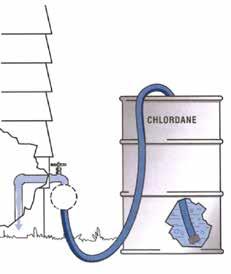
Mixing chemicals with water using a hose is one of the most common, dangerous causes of backflow conditions around the world.
In the above scenario, if there is a drop in supply pressure (before the hose tap) then back-siphonage will occur, sucking the poisonous chemical out of the container and into the household water system. This could also travel into the town supply water main and affect other homes.
When it’s that simple to potentially poison your family, neighbours and community, it makes sense to take a bestpractice attitude towards eliminating the potential harm. In this case a few simple steps are all that’s necessary:
Don’t leave an open-ended hose inside chemical mixing containers
Do install a hose tap vacuum breaker on the outlet of the hose tap, before the hose adapter or hose tail.
These are low cost, high hazard protection devices that will create an air gap as soon as a back-siphonage situation arises, preventing the chemicals from entering the water supply.
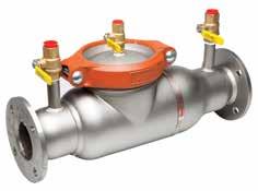
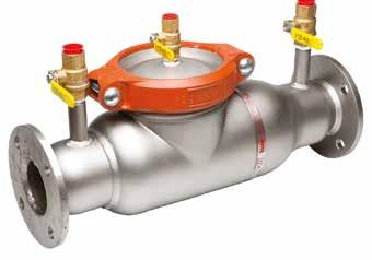
Recommended installation of hose bib vacuum breaker Stainless steel double check valve for medium hazard situations.
Havelock North water contamination
The above example is simple and easier to foresee than some other potential backflow situations, such as the events that took place in Havelock North back in August 2016. Scenes on our TVs showed families queuing by water tankers with large plastic containers—something that we shouldn’t expect in our ‘100% Pure New Zealand’.
Around 5,500 people were struck down with campylobacteriosis, a nasty illness that ranges from stomach pain, cramps and nausea, through to vomiting, muscle pain and bloody diarrhea. Approximately 45 people were sick enough to be hospitalised and it’s possible that the outbreak contributed to four deaths. In addition an unknown number of residents continue to have health issues after the event.
The government inquiry into this event found that farm run-off containing sheep faeces was the likely source of contamination. Due to heavy rainfall, stormwater flowed to a neighbouring pond, from there entered the Te Mata Aquifer and flowed across to an active bore. Contaminated water was then likely pumped into the local reticulation system.
Whilst the specific nature of this contamination was not a normal backflow situation, it clearly demonstrates the widespread effects of unhealthy drinking water, and variations of this scenario can occur easily around the country.
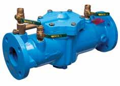
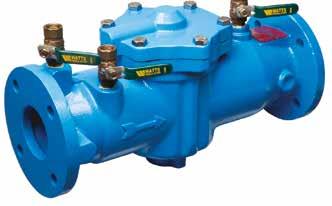
Cast iron reduced pressure zone device for high hazard situations.
Device installation and maintenance
The obvious place to stop backflow from occurring is at source—ideally as close as possible to the likely contamination point. Hose tap vacuum breakers on every tap is a good start, with double check valves or reduced pressure zone devices (depending on hazard rating) at known locations where any sort of processing or manufacturing occurs.
There is no point in installing a backflow device if it’s not maintained. In current legislation, backflow devices connected to reticulated mains water supply require testing every 12 months by an Independent Qualified Person (IQP), with all backflow devices needing to meet AS2845.1 or ASSE.
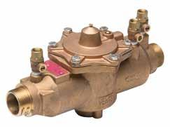
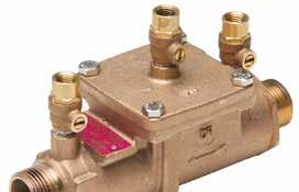
DR brass reduced pressure zone device for high hazard situations.
About the author: Haydon Mace is Technical Lead at Hydroflow, who distribute the Watts range of backflow prevention devices in New Zealand. Watts is an American company with a long history of supplying quality products to the plumbing industry. Hydroflow continues this approach with its breadth of products and depth of technical expertise. A dedicated Technical Team supports the Hydroflow tagline ‘Leading with Knowledge’. If you’re in any doubt as to the best backflow solution for your situation, Hydroflow are here to help.
BACKFLOW SPARE PARTS
Hydroflow stocks an extensive range of Watts and Ames spare parts.
SPARE PARTS FINDER
Download the Hydroflow App to quickly and easily find your required spare part, or scan the qr code to see the full range of backflow spare parts on the Hydroflow website.
Checks Relief Valves Rubber Parts
AKL 09 415 6151 CHCH 03 341 1048 www.hydroflow.co.nz orders@hydroflow.co.nz
Small bore wastewater pump curves
In the third of this series on small bore wastewater pumps, Saniflo give guidance on pump curves.
A pump performance curve indicates how a pump will perform with regards to pressure and flow.
Pump curve basics
Pressure equals head—the height the pump will lift vertically straight out of the unit. The pressure decreases along with the discharge rate, the higher the vertical rise in the pump line.

CHART 1: Typical pump curve.
Pump curves in relation to flow rate
As indicated in Chart 1, the ideal performance range for this pump is 5m head. At this height, the maximum flow rate is approximately 53 litres per minute The optimum performance is generally the halfway point of the flow rate between minimum (zero litres per minute at 8m head) and maximum (97 litres per minute at 1m head), and then seeing where it intersects with the head The head rating versus flow rate is based on a vertical column directly out of the pump. Any additional friction loss on the line will decrease the flow rate and height This flow rate indication is crucial in correctly specifying the pump required for an installation.

Vertical/horizontal performance
Chart 2 indicates how far the pump line can run horizontally on a 1% (1:100) grade after the vertical rise is achieved The pump line must increase in diameter by a minimum of one pipe size within the first 5m after the vertical rise and 1% grade has been achieved This increase cuts down on friction loss in the line and assists gravity flow If 1% grade cannot be achieved, allow 1m head loss for every 10m pumped horizontally.
Fixtures flow rates in relation to pump sizing
The sizing of a pump not only relies on the number of fixtures draining to it, but also on the flow rates of these fixtures This is also important when the pump size may also depend on how high and how far the unit need to pump to its discharge connection point The height a pump needs to lift also reduces the flow rate, which may mean you will have to increase the size of the pump.
Friction loss in pump lines
Friction loss occurs any time a fluid is moving from point A to point B through a pipeline and can decrease the ‘head’, or total vertical performance of the pump. Factors affecting friction loss that can slow down the flow of the material as it flows:
Fluid coming into contact with the internal walls of the discharge pipe
Movement through fittings or valves
Changes of direction within the discharge pipe
All changes of direction must be achieved using 45° bends as this will reduce the friction loss compared to using 90° elbows or bends.
Calculating for friction loss
If the pump line has additional changes of direction or if the specified 1% grade and pipe size increase is not achieved in the first 5m after the vertical rise, the following must be factored into calculating the head loss and the effects on maximum flow rate:
If 1% grade cannot be achieved and pipe size increased within first 5m after the vertical lift, then allow for 1m of head loss per 10m pumped horizontal
Every change of direction (2 x 45° bends = 90°) = 0.5m of head in friction loss
Friction loss in 90° bends can be as significant as 0.7m of head per fitting
The total vertical lift.


