
20 minute read
Dynamic analysis of a novel installation method
There are clear obstacles and hurdles to a smooth This This paper presents the performance of a new, floating, mono-hull wind turbine installation vessel (Nordic Wind) in the installation process. The vessel can transport pre-assembled wind turbines from the marshalling port to the offshore installation site. Each assembled turbine will be positioned over the pre-installed floating spar structure. The primary difficulty lies in examining the multibody system’s reactions when subjected to combined wind, current, and wave forces. Time-domain simulations are utilized to model the interconnected system, incorporating mechanical coupling between components, the mooring system for the spar, and the installation vessel. The primary objective is to focus on the monitoring and connection stages preceding the mating operations between the turbine and the floating spar. Additionally, it involves examining the impacts of wind, current, and wave conditions on the motion responses of the installation vessel and the spar, as well as the relative motions at the mating point, gripper forces, and mooring forces. The simulations show that the resulting gripper forces are reasonable to compensate. The relative motion at the mating point is not significantly affected by the orientations of the turbine blades, but it is influenced by the prevailing wave conditions. In addition, vessel heading optimization can minimize the relative motions at the mating point and gripper forces. Given the examined environmental conditions, the presented installation concept exhibits a commendable performance.
Author: Mohamed Hassan, Principal Engineer Marine Operations at Equinor.
Advertisement


Renewable energy from wind power is expanding globally, establishing itself as a prominent and increasingly significant source of sustainable energy, as the economic conditions are favourable. To address the need for alternative energy sources, a considerable number of wind power generators are being deployed in wind farms, both on land and offshore. European offshore wind capacity grew by adding 3.4 GW of offshore capacity during 2021, reaching a total installed capacity of 17.4 GW. Due to the varying quality of wind resources and geographical constraints, numerous countries are now contemplating the utilization of deep-water offshore areas for future wind power facility development. As of the end of 2020, Europe’s floating wind fleet reached a cumulative capacity of 62 MW, representing 83% of the global floating wind capacity. Floating offshore wind (FOW) is seen as a crucial factor in unlocking Europe’s vast and virtually limitless wind energy potential. Around 80% of the offshore wind resources in European seas are located in waters with depths of 60 m or greater, where traditional bottom-fixed offshore wind (BFOW) installations are not economically viable or attractive.
The world’s first floating wind turbine farm, utilizing Equinor’s Hywind technology from Norway, was commissioned in Scotland in late 2017. The floating wind turbine farm comprises five 6 MW turbines, provided by Siemens. Prior to installation, the turbine blades, nacelle, and tower are pre-assembled onshore. The installation process involves using the SAIPEM 7000, one of the largest semi-submersible crane vessels, to lift and place the components onto the spar floaters in the deep fjord of Norway. Subsequently, the pre-assembled turbines on the spar floaters are then transported via wet towing to offshore Scotland. Once in position, they are connected with mooring systems to secure their stability. The Hywind Tampen project, with a capacity of 88 MW, attained the Financial Investment Decision in 2019 and is currently in the pre-construction phase. The objective of the project is to achieve a cost reduction of 40% compared to Hywind Scotland, which served as the initial demonstration of the spar-buoy technology [10]. Nevertheless, the current installation method still involves assembling the turbines in a sheltered location and then towing each complete assembly individually to the installation site for final commissioning.
To continue cost reduction and development of floating offshore wind projects, the following key areas shall be considered:
• Industrialization: optimize design of substructure and mooring and reduce the cost per ton towards mass production levels.
• Economics of scale: larger parks will drive down costs for infrastructure and logistics.
• Upscaling: follow the bottom-fixed industry towards turbine sizes of 10 - 15 MW.
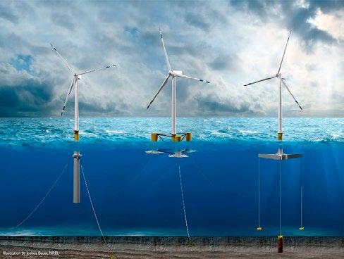
Figure 1 illustrates the three primary designs for floating offshore wind: tension leg platform, semi-submersible, and spar buoy. The semi-submersible and spar buoy structures, unlike the tension leg platform, are loosely moored to the seabed. This loose mooring configuration facilitates simpler installation processes. In contrast, the tension leg platform is firmly connected to the seabed.
• Technology development: establish new and more efficient methods for installation, operation, and maintenance. Offshore wind developers have recognized the preference for new installation methods that rely on cost-effective large crane vessels when developing commercial wind farms. This shift is driven by the aim to reduce expenses associated with installation operations. This will enhance the development of mass production towards potential future long-term markets. In the context of the Hywind installation challenge, there is a preference for innovative installation concepts that prioritize the use of novel installation vessels and facilities. The goal is to minimize offshore lifts and reduce the overall operation time involved in the installation process. The assembly and installation cost for offshore wind turbines (OWT) is relatively high and can account for approximately 20% of the total capital expenditures incurred in the development of offshore wind farms [11–14]. It is, therefore, crucial to employ cost-effective installation methods in order to mitigate the high assembly and installation costs associated with offshore wind turbines. Implementing efficient and economical installation techniques is vital for the overall financial viability and success of offshore wind farm projects.
Current installation vessels
Two common types of vessels used for offshore wind turbine installation are jack-up vessels and floating crane vessels. Jack-up vessels offer a stable working platform for the installation of foundations, allowing for safe and efficient operations. These vessels are equipped with extendable legs that can be lowered to the seabed, providing stability during installation activities. However, the process of installing and retrieving the jack-up legs is time-consuming and highly dependent on weather conditions. Additionally, the stability of the jack-up unit relies heavily on the specific characteristics of the seabed, which can introduce uncertainties. Furthermore, jack-up vessels have limitations regarding the water depth in which they can operate effectively. In contrast to jack-up vessels, floating crane vessels offer greater flexibility for offshore installations and are particularly effective in the mass installation of wind farms. These vessels can swiftly move between foundations, facilitating efficient and rapid deployment. Their enhanced mobility makes them well-suited for large-scale wind farm projects. However, during the installation process, the motions of the floating installation vessel and the lifted objects are intricately coupled and are highly responsive to environmental conditions. This interdependence introduces challenges, as the movement of one affects the stability and control of the other. Therefore, careful consideration of environmental factors is crucial to ensure safe and successful installations. It is important to note that the installation cost associated with floating crane vessels is typically higher compared to jack-up crane vessels. Therefore, when making the selection of a crane vessel for practical operations, a well-balanced consideration between technical feasibility and cost is necessary. Finding the right balance ensures that the chosen vessel meets the technical requirements, while keeping the overall project cost within a feasible range.
Currently, there are ongoing efforts to utilize floating crane vessels for various offshore wind turbine installation tasks. These include the installation of monopile foundations for bottom-fixed wind turbines, the assembly of the tower-rotor-nacelle components for floating wind turbines, as well as the installation of tower-nacelle assemblies and rotors for floating wind turbines. These attempts demonstrate the exploration of alternative installation methods to meet the specific requirements of different types of wind turbine structures. The installation of blades for offshore wind turbines presents greater challenges compared to other components, such as foundations and transition pieces. This is primarily due to the need for precise installation during the final blade mating phase, which demands a high degree of accuracy. Additionally, at significant lifting heights, there is relatively large motion between the turbine hub and the blade root, further complicating the installation process. The combination of high installation precision and substantial motion necessitates careful planning and specialized techniques to ensure successful blade installation. Enhancing the weather window and mitigating unforeseen delays emerge as crucial challenges in reducing the cost of offshore installations. To accomplish this, it is essential to conduct precise evaluations of the installation vessels and methods to gauge their performance accurately. Furthermore, there is a need to develop numerical methods and models that can estimate the dynamic responses of systems during the installation process. These efforts aim to enhance the understanding and prediction of system behaviour, allowing for informed decision-making and optimization of offshore installation operations.
Due to its substantial capacity and cost-effectiveness, the float-over method has gained significant popularity in the oil and gas industry for installing large decks onto offshore platforms. The float-over method offers several notable advantages for installing integrated topsides onto a floating substructure, especially when dealing with large topsides that surpass the lifting capacity of existing heavy-lift fleets. These advantages encompass time and cost savings by allowing the integration and commissioning of modules to take place on land, instead of at sea. Additionally, decoupling the fabrication schedules of the topside from the availability of heavy-lift vessels is another significant benefit.
The innovative installation concept, named by the current author as Nordic Wind, draws inspiration from the float-over method. The primary objective of this concept is to eliminate weather-dependent high lifts conducted from a floating vessel and reduce offshore installation time. This concept has the versatility to be employed for both fixed and floating offshore wind turbine installations.
Installation concept
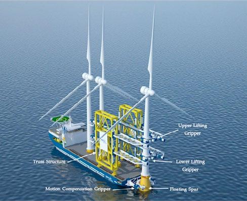
The design of the installation vessel allows for the transportation of at least three pre-assembled wind turbines. The actual number of turbines that can be transported will vary, based on their individual capacity and weight. When compared to the previously mentioned methods, this innovative concept will significantly reduce the need for offshore lifts and installations. As a result, it will lead to a decreased operational time and cost. To ensure a safe installation operation, the vessel is equipped with precisely designed complex mechanisms. The concept includes a motion compensation gripper positioned at the stern of the vessel, along with two lifting grippers and a skidding truss structure system. The connection between the vessel and the floating spar will be established using the motion compensation gripper. The primary purpose of the motion compensation gripper is to minimize the horizontal plane motions that occur between the vessel and the floating spar. The truss structure system is designed with the capability to move in both forward and backward directions. This allows for the selection and lifting of the turbine assembly using both the upper and lower lifting grippers. The design of the lifting grippers should enable them to securely hold turbine assemblies weighing a minimum of 1200 tons.
Additionally, the lifting grippers will be designed with heave compensation capabilities to reduce the impact forces experienced during the mating operation. To secure the floating spar to the seabed, three mooring chain lines will be utilized. On the other hand, the installation vessel will rely on its own thrusters and employ a dynamic positioning system (DP). Figures 2 and 3 illustrate the key components of the installation concept. The stability of the vessel has been assessed under different loading conditions, considering both the transit and installation phases.
Installation procedure
The installation method consists of several key steps, which are as follows:
• Fully assembling the turbine onshore using a crane before the arrival of the installation vessel.
• Loading the turbine assembly onto the installation vessel.
• Transporting the turbine assembly to the installation site.
• Approaching the floating spar with the installation vessel and connecting it to the spar using the motion compensation gripper.
• Transferring the turbine assembly from the installation vessel to the floating spar.
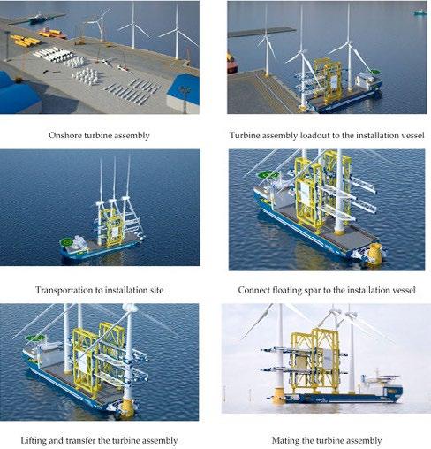
• Mating the turbine assembly in place.
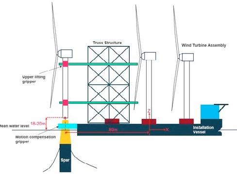
In Figure 4, the installation steps were illustrated starting from assembly, loadout, transportation, and, finally, the mating operation. The installation process will be started once the installation vessel connects the motion compensation gripper to the floating spar. The marine and operational crew will monitor the weather and the forecasted motion and response in order to allow for safe lifting and mating operations. The weather and vessel motions can be monitored by any decision support tool onboard, such as the Octopus system or any other system of the same type. This kind of system can accurately and clearly show how the incoming weather will impact the operation execution. The forecasted motions will be presented in a simple way to aid the crew of the vessel to make decisions based on the available data.
Once the vertical relative motion is within the limits, the mating operation between the turbine and the spar can start. The mating process will be considered complete when the guiding pins located at the bottom of the tower successfully enter the docking device situated inside the floating spar. Once the mating operation is completed, the spar draft will be increased by 5 m - 10 m, depending on the tower weight.
This paper primarily focuses on the monitoring and positioning phases that precede the mating operations. The lifting grippers are not included in the modelling process, since they do not impact the relative motions in the horizontal plane or the forces exerted by the grippers. The design of the lifting grippers should prioritize the minimization of impact forces. These modelling features will be subject to future investigations. Furthermore, an analysis of the operational limits will be taken into consideration.
Dynamic Model

The primary objective of this study is to examine the hydrodynamic performance of the new installation concept during wind turbine installation. To achieve this, accurate and realistic modelling is essential in order to accurately quantify the dynamic responses during various installation phases and critical stages. This detailed analysis will facilitate improved operational planning. There are several key challenges to model the entire installation process.
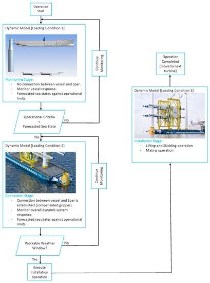
To overcome the above challenges, the dynamic model has been divided into several key stages in the next, and are explained as follows:
Dynamic system stages for the installation phase.
Loading condition 1: which corresponds to the monitoring stage, where structure responses are monitored prior to gripper connection.
Loading condition 2: which corresponds to the connection stage between the floating spar and the installation vessel.
Loading condition 3: which corresponds to the installation phase for lowering the turbine to the floating spar (mating operation).
Numerical Model
The coupled dynamic system of the installation vessel and the floating spar was simulated and modelled using ANSYS AQWA software for numerical analysis. ANSYS AQWA offers a comprehensive set of tools specifically designed to analyze and assess the impact of environmental loads on various types of offshore and marine structures, including both floating and fixed structures.
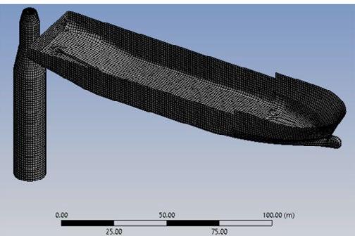
The global coordinate system (GCS) employed in this context is a right-handed coordinate system. Its orientation is defined as follows: the X-axis points towards the bow, the Y-axis towards the port side, and the Z-axis points upwards. The origin of the GCS is situated at the mid-ship, center line, and still waterline position when the vessel is at rest. Each floating body exhibits six degrees of freedom. Assuming a linear and harmonic response, the coupled differential equations of motion for the floating bodies can be expressed in the following format:
Frequency domain
In the present study, the added mass and potential damping were computed in the frequency domain and subsequently utilized in time domain simulations. These calculations were performed to analyze the coupled motion of two bodies through the implementation of retardation functions. The analysis also considers the viscous damping effects on both the vessel and spar. Figure 7 illustrates the hydrodynamic panel model employed for the installation vessel and the floating spar. The calculations incorporate first- and second-order hydrodynamics, based on the potential theory. Figure 8 depicts the Response Amplitude Operators (RAOs) for heave and pitch motions of both the installation vessel and the spar. These RAOs were evaluated under specific sea conditions, known as following sea conditions.
The utilization of the generalized mode concept proves to be effective in addressing multi-body hydrodynamic interaction problems. By employing this concept, a multi-body system consisting of NB body units can be represented by 6 multiplied by the number of bodies (6XNB) degrees of freedom, assuming that each body behaves as a rigid body. In the case of multi-bodies that are hydrodynamically and mechanically coupled, the equation mentioned above needs to be solved in a coupled matrix equation. In the model, the installation vessel and the spar foundation are represented as two rigid bodies that are interconnected through mechanical and hydrodynamic couplings at their interfaces. Both bodies experience wave-induced forces, hydrodynamic reaction forces, and mechanical coupling effects.
The equation of multi-body motion is given below:
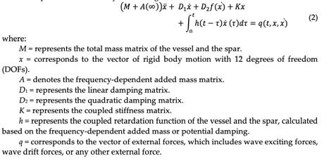
In this initial study, all wind turbine assemblies present on the installation vessel are connected rigidly. Mooring systems were separately incorporated for both the spar and the installation vessel.
Wind Loads
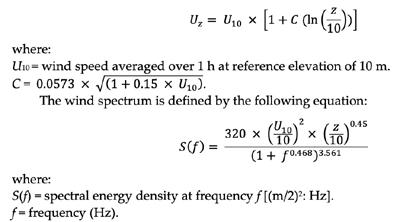
Within ANSYS AQWA, wind loads can be simulated using various spectrum options or by specifying a constant velocity. This allows for flexible modelling of wind-induced loads in the analysis. The wind field in the analysis is assumed to propagate parallel to the horizontal plane. The fluctuating component of the wind velocity in the mean direction is described using the NPD spectrum, as defined in API RP2A. This spectrum provides a characterization of the varying wind velocity for the simulation. The average wind speed profile at a specific elevation z, denoted as Uz, can be approximated by the following equation:
Current loads
In this study, the current was modelled using the power law method, where the current direction remains fixed and does not vary with depth. The current speed, denoted as S, varies with position (X, Y, Z), according to the following formula:
In the present study, the wind forces generated by the wind turbines installed on the vessel deck were considered. The wind coefficients required for the calculations were determined using HAWC2 software. The wind coefficients for the installation vessel were obtained through model tests. Figure 9 illustrates the changes in force and moment coefficients, with respect to wind direction for the wind turbine.
Specifically, two blade orientations were taken into consideration: blade pitch angles of 0 degrees and 90 degrees.
Mechanical coupling
Understanding the effects of modelling mechanical couplings on the dynamic characteristics of a system is important. In this study, the mechanical coupling between the ship and the floating spar substructure was achieved using a motion compensation gripper.
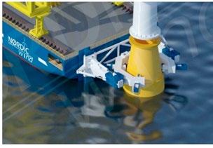
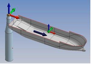
In the dynamic model, the motion compensation gripper is simplified using a mechanical joint. This mechanical joint enables independent rotation of both bodies, allowing them to move freely, with respect to each other. However, it should be noted that, despite the independent rotation allowed by the mechanical joint, the two bodies will remain rigidly connected in the longitudinal and transverse directions. The primary objective of the motion compensation gripper frame is to facilitate the installation process by compensating for the relative motions in the horizontal plane between the floating spar and the installation vessel. By mitigating these relative motions, the motion compensation gripper frame helps to ensure smoother and more efficient installation operations. Figure 10 shows the mechanical joint between the installation vessel and the floating spar, as modelled in ANSYS AQWA.
Figure 9.
(a) Wind force coefficients for blade pitch 90 deg;
(b) Wind moment coefficients for blade pitch 90 deg;
(c) Wind force coefficients for blade pitch 0 deg;
(d) Wind moment coefficients for blade pitch 0 deg.
Mooring System
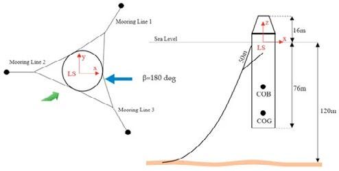
The mooring system for the spar is composed of three separate lines that are connected to the substructure through bridles. The pretension and configuration of the bridles provide sufficient yaw stiffness, which helps prevent slack in the mooring lines during normal operation. This ensures the stability and proper functioning of the spar structure.
behaviour before introducing the mechanical gripper connection. Moreover, it was feasible to assess how the hydrodynamic interaction between the two bodies affected the resultant movements of the motion reference point (MRP).
Results and discussion
The primary goal of the study is to assess the performance of the installation concept under varying wind, wave, and current conditions. To achieve this, multiple time domain simulations were conducted, considering different environmental conditions specific to the Hywind Tampen location.
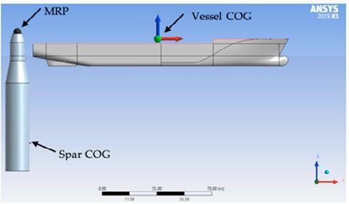
For time-domain simulations, some reference points are considered to give insight into vessel and spar motions. The following points are considered and shown in Figure 12:
Hydrodynamic interaction
The computation of linearized hydrodynamic wave-loading on floating bodies is performed using AQWA-LINE, which utilizes three-dimensional radiation/diffraction theory. The concept of fluid interactive loading between bodies is commonly discussed in the context of radiation/ diffraction theory. Radiation forces, in essence, pertain to the impact of one body’s flow field on another. The significance of such interaction depends on factors such as the separation distance between the bodies and the relative sizes of the bodies involved. During the connecting phase between the installation vessel and the floating spar, the importance of this interaction becomes apparent as the two bodies come into close proximity. In addition to the radiation coupling, the hydrodynamic interaction also includes the shielding effect, which refers to the change in the flow field around a body due to the presence of another nearby body. This effect can have a significant impact on the wave loads and motions of the interacting bodies.
A series of time domain simulations were initially conducted without incorporating the mechanical gripper connection between the installation vessel and the spar. These simulations aimed to assess the dynamic behaviour and response of the system under various operating conditions and environmental loads. By conducting these simulations, it was possible to establish a baseline understanding of the system’s
•
• Spar center of gravity (Spar
• Motion reference point (MRP).
The motion reference point (MRP) is located at the top of the spar. The mean value for the vertical motion at the MRP is 16.0 m from the water level.
Multibody interactions effects
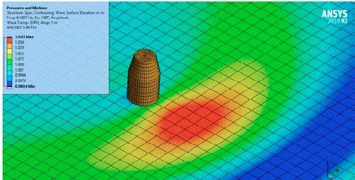
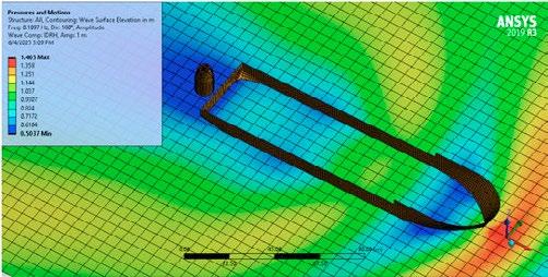
As can be seen in Figure 13, the hydrodynamic interaction effects are variable and can be seen over all wave peak periods. When considering a wave period of 9 s, as an example, the wave surface elevation at the spar is less when considering multibody interaction (vessel and spar) and spar only, as shown in Figure 14 and Figure 15. Figure 15 show the maximum and the minimum relative motions at MRP, with and without multibody interaction, for various wave peak periods ranging from 6 - 12 s, with a maximum significant wave height of 2.5 m and wave heading of 180°.
This explains the reduction in the longitudinal and vertical motions at the motion reference point (MRP).
Since the lifting grippers do not affect the relative motions in the horizontal plane, they were not modelled in the simulations evaluating the performance of the motion compensation gripper.
Gripper forces
Figure 16 shows the gripper forces in the x and y directions. The forces are presented for Hs 2.5 m and wave heading of 180°. As can be seen, the multibody interaction has more effect on reducing gripper force in the x direction compared to the y direction. Figure 17 shows the standard deviation of gripper forces in x and y directions, respectively.
Figure 16. (a) Maximum gripper forces at the x direction, with and without multibody interaction; (b) Maximum gripper forces at the y-direction, with and without multibody interaction.
Figure 17. (a) Standard deviation gripper forces at the x direction, with and without multibody interaction; (b) Standard deviation gripper forces at the y direction, with and without multibody interaction.
Figure 18 shows results for the gripper forces in the x and y directions for different wave headings. The results show that the force in the x direction is more sensitive to the wave heading compared to the force in the y direction. Figure 19 presents the results of the vertical relative motion at MRP for different wave headings and significant wave heights. Figure 20 shows the results of the gripper forces for different significant wave heights. The results presented in Figure 16 to Figure 20 shall be used together with the onboard weather forecasted decision tool to further optimize the mating operation.
Figure 13 illustrates a comparison between the maximum and minimum relative motions at the motion reference point (MRP) for both the installation vessel and the spar. The mechanical gripper will function to compensate these motions to facilitate and ease the turbine mating operation. In addition to compensating for the relative motions between the installation vessel and the spar during the connection phase, it is also important to address the heave motion of the installation vessel during the lifting and mating phase of the wind turbine assembly.
This can be achieved by implementing a control system for the lifting grippers that compensates for the heave motion of the installation vessel, ensuring a safe and efficient mating operation.
Figure 18. (a) Maximum gripper forces at the x direction for different wave headings; (b) Maximum gripper forces at y direction for different wave headings (Hs 2.5 m and Tp 12 s).
Figure 19. (a) Minimum and maximum Z-relative motion at MRP (Hs 2.5 m and TP 12 s); (b) Minimum and maximum relative motion for different Hs and Tp 12 s.
Conclusions
The main findings of this study can be summarized as follows:
Figure 20. (a) Maximum gripper forces at x direction for different wave headings; (b) Maximum gripper forces at y direction for different wave headings (Heading 180 deg and Tp 12 s).
Figure 21 shows the effect of the wind and current on the gripper forces. Two blade pitch angles, 0 and 90 degrees, respectively, were considered. As can be seen, an increase in the gripper forces in the x and y directions were observed. The wind and current has more effect on the gripper force in the x direction compared to the gripper force in the y direction. Moreover, the effect of wind on the gripper forces is higher when the blade pitch angle is 0 degrees, compared to a blade pitch angle of 90 degrees.
• Offshore wind turbine installation concept: The study proposes a new method for installing offshore wind turbines using a floating vessel. The concept involves the use of a numerical model that includes a floating vessel, a spar foundation, a mechanical gripper, and mooring lines.
• Monitoring and positioning phases: The study focuses on the monitoring and positioning phases that precede the mating of the wind turbine assembly. These phases are crucial for ensuring a successful installation process.
• Multibody interactions: The study explores the impact of multibody interactions on the installation process. It demonstrates that these interactions have a substantial effect on reducing relative motions and gripper forces within a specific range of wave periods (6 - 9 s). However, their influence becomes negligible as the wave period increases.
• Relative motion: The relative motion between the wind turbine and the spar at the mating point is identified as a critical factor in the success of the mating operation. The study determines that this relative motion is primarily influenced by the first-order motions and is particularly sensitive to the significant wave height and wave peak period. However, it is found to be less affected by wind and current conditions.
Figure 21. (a) Maximum gripper forces at x direction, including wind and current for blade pitch angles of 0 and 90 degrees, respectively; (b) Maximum gripper forces at y direction, including wind and current for blade pitch angles of 0 and 90 degrees, respectively.
Mooring Line Tension
Considering the mooring layout and wave headings illustrated in Figure 11, it is anticipated that lines 1 and 3 will endure higher loads compared to line 2. The top tension in line 1 at β = 180 deg, Hs of 2.5 m, and Tp of 12 s, is studied here. Figure 22 presents the dynamic top tension for three conditions: wave only; wave, wind and current for blade pitch angle of 0 degrees; and wave, wind, and current for blade pitch angle of 90 degrees.
As can be seen in Figure 22, the mooring line tension has increased due to wind and current effects. Furthermore, it is worth noting that the mooring line tension experiences a significant increase when the blade pitch angle is set to 0 degrees, as compared to when it is set to 90 degrees.
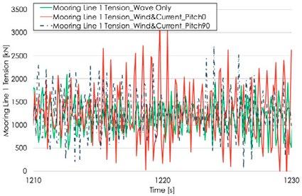
• Blade orientations: Two blade orientations, with blade pitches of 90 degrees and 0 degrees, respectively, are considered in the study. It is observed that the choice of blade pitch has an impact on low-frequency motions and mooring line tensions. Specifically, the 0-degree blade pitch leads to a greater increase in the tension forces compared to the 90-degree blade pitch. Gripper forces, on the other hand, show less sensitivity to blade orientation angles.
• Gripper forces and hydraulic cylinder capacity: The study finds that the resulting gripper forces are within reasonable limits for compensation. These forces can be utilized to determine the appropriate hydraulic cylinder capacity for relative motion compensation during the installation process.
• Vessel heading optimization: The study highlights the importance of vessel heading optimization in minimizing relative motions and gripper forces between the installation vessel and the floating spar. For example, the gripper forces in the x direction are more sensitive to wave heading compared to the y direction. This optimization can facilitate the mating operation and reduce the impact force. Decision support tools, such as the Octopus system, are suggested for monitoring weather and vessel motions, providing accurate information on how incoming weather conditions may affect the operation execution. These tools can guide offshore crew in the optimization process.
You can find the complete article on mdpi.com/2077-1312/11/7/1373


