24 minute read
the material of the model
On The Surface: Metis 2000-2014
Richard Collins
Advertisement
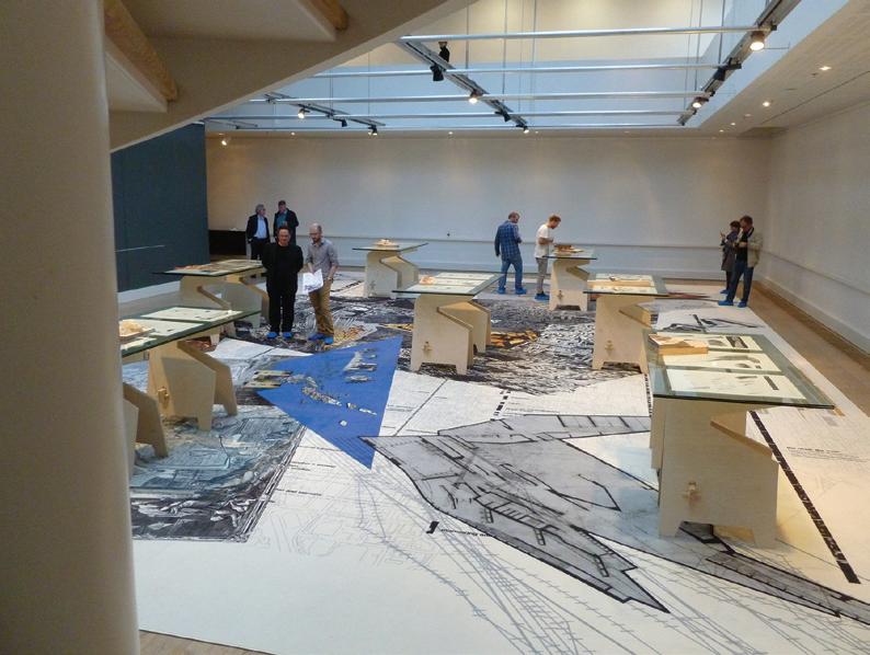
In the autumn of 2014 the Aarhus Arkitektskolen exhibited On The Surface, a retrospective of the work of Metis, an atelier for art, architecture and urbanism. The show was re-exhibited in the Sculpture Court of the Edinburgh College of Art in the spring of 2015. The work on show featured seven projects that Metis had developed between the years of 2000 and 2014.
The exhibition comprised three primary modes of representation: models, drawings and one large composite drawing – a carpet, measuring 10m by 16m, that was printed with a carefully photo-montaged collection of imagery from the seven projects, including drawings, photographs and renders. This drawing provided a spatial anchor that located seven tables, each constructed from two sheets of glass layered on top of a pair of bespoke wooden trestles. Sandwiched between each pair of glass sheets were three drawings printed on a matte watercolour paper. On top of each table, unrestricted by vitrines, a model was situated.
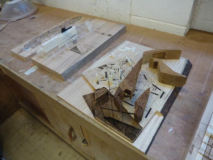
Of the seven models, I had begun work on one in May 2014, but primarily as a resource to be photographed and which required further development. One model was comprised of original material from an installation in Glasgow, 2005. For the remaining five models, made specifically for the exhibition, I worked with a range of tools and techniques and drew upon material which included drawings and sketch models.
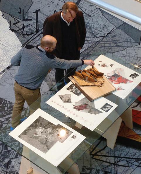
above: On the Surface exhibition when it was at Aarhus Arkitektskole. View from gallery: models on drawings on carpet below: Models under continual construction
all images: richard collins
On the Surface exhibition
all images: richard collins
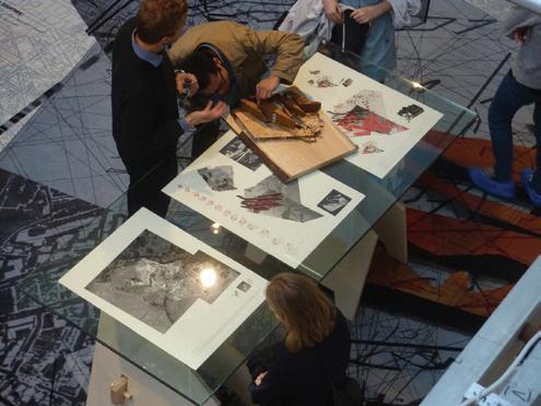
On the Surface exhibition
all images: richard collins
Apersuasive architectural model demands close attention; it requires observation from more than one perspective; it demands to be touched. It has a material presence that tells of its construction and its condition. It is a distilled synthesis of an idea. It is the summary of a process of design, the communication of a method of making and is the result of an explorative speculation. The meaning and significance of the model is not arrested, but is open to interpretation. The fragmentary nature of the model, its island condition, suggests an alternative reality. The form is clearly different from what it signifies, yet what it presents can be recognised, imaginatively transformed and abstractly occupied.
The most influential force changing the nature of models, both their form and how they are made, comes from advances in digital fabrication and related technologies. However, digital technologies can encourage linear and unproductive methods. With the application of digital fabrication there can be a simplification of material, whereby material complexity is compromised to achieve formal complexity, or expediency. I would argue that the advantages of using digital fabrication for model making are when the technologies are not used in an automatic or algorithmic manner, but with a reflective and critical understanding of making. Moreover, in order to be sensitive to the materials that are chosen, one must consider the material properties early in the process of design rather than at the point of using the technology.
Also, digital technologies can encourage linear and unproductive methods. The advantages of using digital fabrication for model making are in a more productive approach that does not use the technologies in an automatic or algorithmic manner, but with a reflective and critical understanding of making.
When a Computer Numerically Controlled Router (CNCR) is used to manufacture components at a 1:1 scale for construction, clearly it is important to specify the material properties in advance and be confident that those properties are predictably. However, when a CNCR is used not for a 1:1 constructional detail, but for an explorative and speculative representational model, how can a method of working be developed that ensures a material sensitivity?
Simplification of material is evident across a range of digital fabrication technologies, otherwise known as Computer Aided Manufacturing (CAM) technologies, including both additive techniques such as 3D printing and subtractive techniques such as laser cutting and Computer Numerical Controlled (CNC) routing. CNC routing is closest in nature to more traditional techniques of making, a cutting tool is directed into a medium and material is removed. Unlike the application of laser cutting, the workpiece and the cutting tool come into physical contact. The nature of the material, its geometry and density, its melting point and the presence of a grain or any irregularities affect how it is machined. The favoured materials for CNC routing are foams, modelling boards and manufactured boards such as MDF or plywood, but also natural softwoods and hardwoods. Despite the differences between these materials, they are frequently treated as a predictably consistent, plastic substance. Material complexity is sacrificed to achieve complexity of form.
When digital tools are used on materials, the properties of the materials have to be calculated prior to fabrication. The dialogue between architect and the material of construction is altered. Without digital fabrication, representative drawings are interpreted by those who will construct the project. This interpretation involves a knowledge and understanding of material that will critically inform how the construction is realised. With digital fabrication architects generate coded data that scripts the process of construction directly via technological applications. How can a method of working be developed that ensures a material sensitivity is retained? How can a process develop into a sophisticated technique, that does not negate, not rout out, but critically investigates and responds to material?
In the same way that a model – its making, its material, its model-maker – is able to discard preconceptions and conventions in the process of its making, I wish to take two examples of models and how they were made to show the complexity of materials and how digital fabrication is both confounded by and exploits their qualities.
There were several contexts in which these models were constructed: the virtual space of a Rhino model; the workshop environment in which they were made; and the site of display in which they were exhibited. The experience of making two of the models, Egypt and Liepaja, are detailed here to show how contingent and provisional is the relationship between tools, material and intentions.
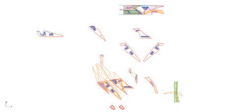
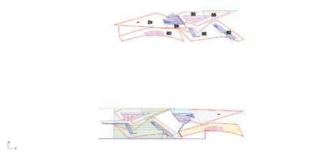
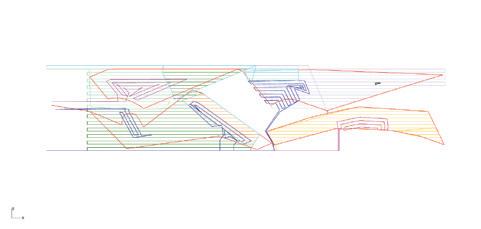
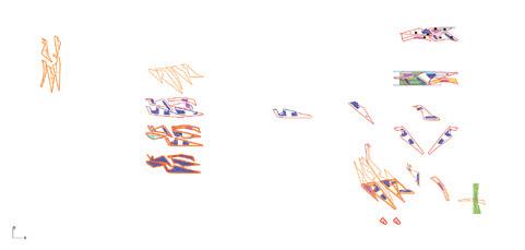
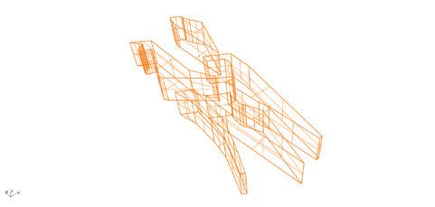
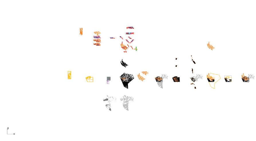
Computer Aided Design (CAD) for Computer Numerical Control (CNC): A set of instructions is developed for the router. In addition to drawing outgeometry, layout and orientation are also described. Colour is used bothto distinguish parts and also to articulate stages of machining. Idealsof form are depicted. Multiple versions are expanded to explore optionsand alternatives.
all images: richard collins
Egypt
The model for Metis’s Great Egyptian Museum project was the most challenging and in many ways the most engaging. Metis’s starting point for their proposal was the renowned measurement of the pyramids in carried out in 1881 by the archaeologist Flinders Petrie, a survey carried out through a triangulation of projected lines. Metis took a representation of the geometrical lines from the site of the survey and folded and refolded them onto the proposed site of the museum. The brief for the museum required a series of galleries and archives to house the Egyptian national collection of antiquities. Metis proposed that the galleries take the form of five large ‘vessels’, grouping the collection into curated themes of culture, scribes and knowledge; religion; man, society and work; kingship and state; and the land of Egypt. Each vessel had a unique and complex geometry but was also understood as being part of a coherent whole. The material proposed for the actual construction of the vessels was weathering steel and it was important that the set be closely linked by their common materiality,. These vessels would be interlinked by a series of bridges allowing visitors to create their own itinerary. The vessels were raised above the ground, creating a constructed landscape of shaded, interconnected folded planes.
As part of their competition entry, Metis had constructed a card model. The model showed a sectional cut through the ground, folded landscape and the five vessels, revealing floor plans and points of connection. The new model required for the exhibition used a palette of materials. The ground was represented by solid hardwood with the folded landscape above made from planes of plywood. The structures holding the vessels above the ground, the internal floors and the bridging elements would be 3D-printed. A dark and very dense tropical hardwood was chosen for the vessels to impart a heavy, monolithic feeling, with intricately embellished surfaces. The choice of material (in both cases, model and proposed building) signified a crisply folded precise wrapping and protective securing of a more delicate interior.
The process for making the new model began by digitally tracing hand-drawn plans and taking references from the card model. This information was aggregated in a digital model, with elements coded by colour, in layers and in groups, resulting in a dense set of digital material (see the drawings to the left). Rather than one illegible stack, several iterations and selected model parts are arrayed in the virtual space. The distances between the parts are not arbitrary but located at specific distances, allowing multiple virtual iterations to be moved back and forward in connection to other virtual material. Sections that would be laser cut could be worked on independently and then checked back against sections that would be CNC-routed or 3D-printed. As well as modelling in three dimensions, two-dimensional nets mapping the facades of the vessels were digitally unfolded, rotated and categorised in isolation.
The typical materials used for CNC routing are flat, uniform and have a consistent density – typically MDF, plywood or modelling foam. Standard techniques include a ‘safe margin’ around the area to be cut. The wood selected for the base of the Egypt model had an irregular form but was relatively straightforward to machine. When preparing to CNC rout this piece it was necessary to establish a way to reference the digital model to the physical. This did not require a faithful modelling of the exact physical dimensions of the wood in virtual space, but only the more significant points of calibration. The tool paths that were generated were designed to extend beyond the material present to ensure the desired areas were fully machined.
Routing hardwood to create the vessels proved more challenging. The hardwood selected had been salvaged from a furniture workshop that was no longer operating – it was not possible to find any more material that matched the density, colour and texture. The dimensions of the block would accommodate the cutting of the five vessels. The geometries of the vessels were outside the standard limits of the CNC equipment. On the first attempt a failure resulted from using the automated software supplied with the CNC. The software script instructed the cutting tool to travel directly from one cutting stage to the next. As a result, unable to lift the cutter high enough (because the wood was outside of standard limits), the tool travelled through the block damaging the piece. The clash was spotted quickly and the damage limited, luckily there was enough material left in the remaining volume to machine all five blocks.
The CNC automated programme was no longer a possibility, but it was possible to rewrite the scriped movements. The solution was to digitally draw vector paths for the cutting tool that would ensure the cutter would never need to lift whilst in the work-piece. The tool would approach the work-piece at the appropriate depth and would cut a trench along a predefined path without rising from that path until outside the hardwood. The machining could also be paused to allow the tool to be extended further when appropriate. Writing the tool paths involved drawing two-dimensional pathways on drafting software, establishing different depths with colour coding, and calculating effective offsets for each line based on the radius of the cutting tool. When each of the pathways had been drawn, the combined drawings were outputed as g-code. After the experience of the first failure, the cutting pathways were first tested with a low density, low-cost foam.
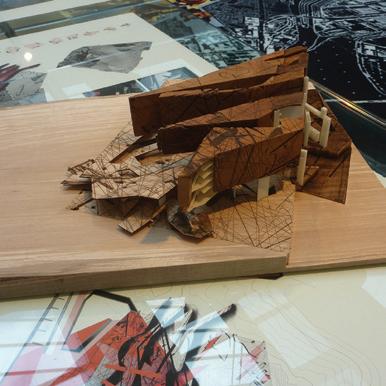
The Great Egyptian Museum project: Folded web, vessels and hyperlinks Card model by Metis (left).
all images: richard collins
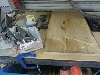
Routed ground condition in spalted beech
all images: richard collins
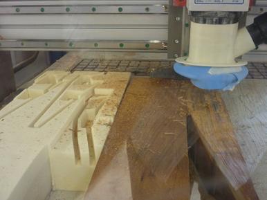
Testing tool paths in low density foam
all images: richard collins
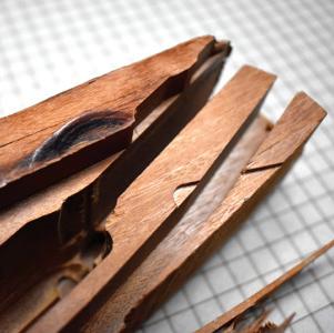
Unexpected clash between routing tools and material
all images: richard collins
The foam was used to highlight any miscalculations or unforeseen errors. After this trial run, the hardwood was carefully secured, the cutting tool calibrated and the machining speeds set. The subsequent machining would last more than 20 hours and was processed in stages over three days, with frequent checks. The tool-paths were drawn with the inclusion of tabs, sections of cutting that were omitted and that would hold the pieces in place. They were positioned with the intention of being easy to remove, that is on straight flat sections rather than on corners. After the CNC routing process was finished the five pieces were cut free using a bandsaw and tenon saw. Once separated into individual pieces, the surfaces were smoothed using chisels and sandpaper.
The next stage, which involved the laser cutter, also presented challenges. Laser cutting is typically performed on flat sheets of stock material with an orthogonally referenced starting point. Often, if a mistake occurs when cutting a design, a new piece of material will be inserted and the cut performed a second time. In contrast, for laser engraving our vessels, the laser was required to engrave precisely on multiple sides of the three-dimensional forms. The forms already embodied a considerable amount of work and any misalignment would have been clearly visible. The strategy developed involved positioning the block and sending small marking lines with very little energy so that only a small trace of burning would be left on the wooden surface. The position of the trace was observed, followed by adjustment and recalibration. This process was repeated until the correct position was found and a stronger engraving command could be sent. There was a further repetition, engraving more darkly and more deeply. Four to five repetitions were typically required before moving on to the next facet. There was a significant amount of handling, positioning, propping and securing.
all images: richard collins
all images: richard collins
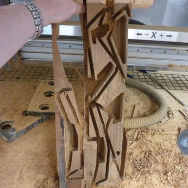
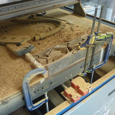
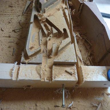
The hardwood is secured for machining with clamps, screws and weights. Channels are carved, cutting around the desired forms Post-machining,the block is removed but far from finished
all images: richard collins
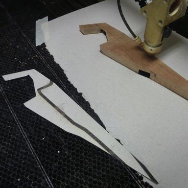
Positioning the vessel in the laser cutter with a card jig.
all images: richard collins
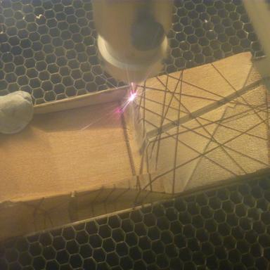
The vessels are manually rotated and secured by whatever means possible.
all images: richard collins
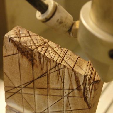
A close up of a vessel mid-way through laser engraving.
all images: richard collins
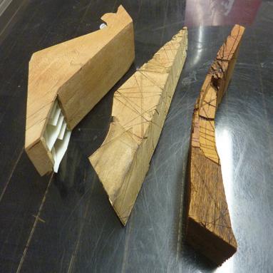
Routed form and 3D printed inserts, laser-engraved surfaces and oiled finish.
all images: richard collins
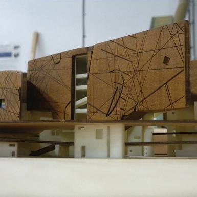
View from ground surface towards folded ground planes and elevated vessels.
all images: richard collins
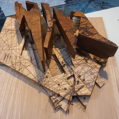
Eroded material and marked surfaces.
all images: richard collins
Liepaja
In May 2014 an architectural competition was announced to develop a derelict bathhouse in Liepaja, Latvia. My experience with this project was quite different from all of the other models I made for the On The Surface exhibition. With the other projects I was working with material that had already been developed for past competition. The model for Liepaja however was developed in collaboration with Metis in order to be photographed for competition boards alongside drawings, computer renders and textual description. The photographs included a perspectival section illustrating the proposed interior, the screen wall and the gardens and an arrayed collection of individual parts. In order to be exhibited the project had to be developed into be a coherent whole.
The most fundamental aspect of the project was the dialogue between the architecture of the existing bathhouse and the proposed architecture that would face it. A sectional model was key to show how the connection between the two architectures would be articulated via a series of parallel gardens. For the model, these strips needed to be more than a superficial etching, they needed to be clearly embodied in the material composition of the model. The proposed intervention in the original bathhouse was a transformation of the rooms that had contained baths, into spaces that could be entirely filled with water: bath-rooms. To show this in a clear and powerful way only the intervention would be modelled, the existing structures would be represented via etching. The new building, proposed to complement the existing bathhouse included private apartments with mezzanine levels, rooftop pools and a carefully defined interface of public and private areas. Using 3D-printing allowed for sharply detailed structure in a uniform material that foregrounded the spatial arrangement.
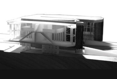
The feature of the proposed architecture that required most resolution was the external screen wall. This perforated wall formed a boundary that would filter both light and lines of sight between interior and exterior. This element proved very challenging to create. The form of the boundary was complex, similar to a ribbon of varying thicknesses, wrapping in and out around the building forms. There were moments when the boundary ribbon would join back on itself. The form had integrated staircases and extruded sections that specifically related to the forms that it masked. Its character demanded a coherent form – a single entity that was distinct from the rest of the model.
The perforations in the modelled screen had to be carefully proportioned, abstracted sufficiently from the literal dimensions that were represented so that they would read appropriately at a scale of 1:200. At 1:1 the perforated wall would be relatively straightforward to construct and smooth. Bricks would be placed according to a rationale of solidity and openness and changes in geometry would use the physical dimensions of the bricks and a gradual alteration of how they would be placed. At a scale of 1:1, faceted corners would read as curves. However, the techniques associated with hand (or machine) laid bricks are not directly scalable to a 1:200 model.
Three approaches were developed to make the scaled-down peforated wall; each required several stages of abstraction and adaption. The least successful approach was FDM printing. The stated resolution of the ‘Dimension Elite’ is 0.178mm; this refers to the height of each layer that is extruded. On paper, or more aptly on screen, this approach should have worked. However the test pieces proved unconvincing. Even with an abstraction or exaggeration of geometries the material did not look promising. There was very little tactile appeal and the appearance too closely resembled the printed apartment interiors it was supposed to contrast with.
The colour, texture and grain of laser-cut wood was much more appealing. Initial tests using this second approach of cutting a perforated pattern onto a flat section proved persuasive. There was a requirement to adapt the geometry to account for the material ‘lost’ through being burnt away, but such adaptations could be made relatively quickly using CAD. Design options were tested on sample materials, the resulting perforations were reviewed and the design adapted as required. Cutting patterns on the curved sections was much more difficult and required careful manipulation and fastening of the work piece. If the whole piece were kept intact certain sections would be impossible to laser cut. Prior to lasercutting any perforations, the wooden form was created through CNC routing. First tested on a piece of cheap readily available softwood, pine, the exploration developed an understanding of the physical form and what level of detail could be expected. The problem with using this type of wood is that the open nature of the grain (characteristic of the tree’s fast growth) is prone to splitting and cracking, particularly problematic when thin sections are cut across the grain of the wood. However, without doing this, it was impossible to achieve the geometry of the screen wall that was desired.
Before routing a block of hardwood, adjustments were made using the knowledge gained from working on the block of pine.
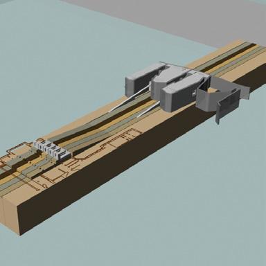
A digital model maps out the material requirements of the physical model
all images: richard collins
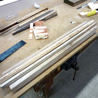
above: Materials are selected and brought together to test adjacencies
all images: richard collins
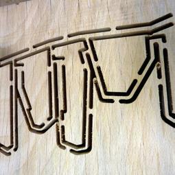
CNC routed beech, stage one of machining.
all images: richard collins
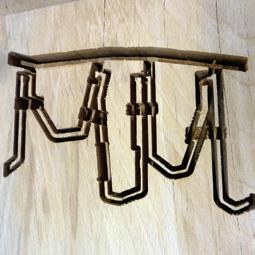
Stage two, the block of beech is flipped over and machined from the underside.
all images: richard collins
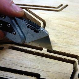
Post-machining, the securing tabs are carefully removed
all images: richard collins
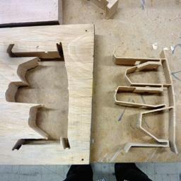
The single piece has been machined and cut free, the offcut material can be seen on the left.
all images: richard collins
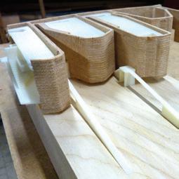
Markings from the cutting tool can be seen on the façade. 3D printed components are slotted into place and adapted if required.
all images: richard collins
Critical sections of geometry were thickened. The block was also referenced so that it could be machined from both sides. Machining tabs were included that held the piece together during the automated process and were then cut away using a bandsaw and tenon saw. The sequential series of machining passes created an expected and quite appealing texture. To machine a block of wood in this way is not an efficient use of material; if there were a requirement to make multiples of the form such an approach would be difficult to justify economically.
A considerable amount of time, effort and material had been put towards the creation of the CNC routed piece. If the form were left uncut it would have a greater physical presence when experienced directly. However, if the form were sectioned the subdivided pieces could be laser-cut creating the perforations that were so significant to the design. The experience of the perforated subdivision would be especially persuasive when experienced through photography and enlargement. At the time of the competition, photography of the model took priority and the form was divided. By cutting, even with a fine saw, material was removed. If the pieces were to be re-joined, the form would be distorted.
This led to me trying out a third approach. The third approach involved using the Objet printer, which uses polyjet technology. The stated resolution of the ‘Objet Connex 260’ is 0.03mm. The accuracy is much better than with the Dimension Elite and it is possible to print in a range of materials. However, when printing details smaller than the recommended limits, cleaning away the support material is problematic. The structure of the secondary support material will break down in water, but it does not dissolve, it only delaminates. Problems can occur because the model material that is used alongside the support is hygroscopic, and when it draws in fluid it becomes weaker. As the structure of the support material breaks down it expands and can cause the weakened model material to break.
During the testing phase there were several ruptured walls, the breakage occurring at the stage when the support material was being removed. The more support material there is relative to model material, the higher the chances of breakages. If the support material can be manually scraped off, then delicate structures stand a much better chance of survival. After using a chisel to scrape off the surfaces, a pin was used to prod out support material from the perforations. The support material is a jellylike, soft waxy material that crumbles relatively easily. However it does adhere to the surface of any model material that is supported by it. The surfaces of such supported sections have a matte roughness that contrasts with any unsupported surfaces, which will be much glossier. To remove more support material and improve the surface quality the forms were hand-sanded. After an acceptable smoothness was achieved with a rough grade of sandpaper, the same process was continued with increasingly finer grade sandpaper. When the majority of support material had been removed, a small amount of water was introduced with wet-and-dry sandpaper to ease the action of sanding and aid the removal of debris.
Out of the three approaches this was the most successful. However, it was not a complete success as under the heat of the exhibition lighting an extended section started to deform. This challenge was addressed hours before the opening with some materials that came to hand.
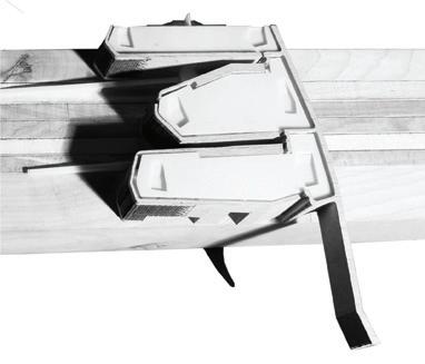
Photographed model, from above and in section.
Looking here at the models and the complexities of their making for the On The Surface exhibition, I discovered much about tools, materials, techniques and intentions. Tools have been developed to shape material; they are capable of more applications; they can perform more efficiently; they have limitations. The limitations of CNCR is dependent on the materials used. Materials most commonly used with CNCR are compliant – metal, foam, man-made boards are much less resistant to the pressures of making. They too have their limitations and often privilege sight over tactility. Nor are the limits always physical, sometimes they are no more informative or persuasive than a virtual model. Less homogenous materials with similar physical limitations can be more informative and more persuasive because they are not neutral, because they offer resistance through grain, knots, spalting and colour variation to the attitude of the maker. Such materials come with associations, that are haptic and tactile, not just visual. Techniques have been developed for working with wood using tools, while work flows have been developed for using plastic materials with CNCR. What techniques have been developed for working with wood using CNCR? Techniques discovered in the making of the On The Surface models embody four things:
1 knowledge of how materials come together, a testing of construction
2 simplification of an idea in order to embody the essence of the project
3 creatively using one material to represent another
4 a cycle of testing, not a linear production; a process of testing, an attitude of testing
Why make a physical model? To re-state something I said at the beginning of this essay, a persuasive model is the sum result of a design process. It communicates a method of making and the results of speculative exploration. It has a material presence that tells of its construction and condition, without arresting its meaning or significance, that remains open to interpretation. Its fragmentary nature, its island condition presents a form that is recognisable, able to be imaginatively transformed and abstractly occupied. In model-making there is deliberate allowance for the unexpected in response to material resistance. There must be an openness to redesign that allows the material to inform process. Judgement in making is not easily programmed or calculated, it is not a linear process. Fundamental is an understanding of the translation that is required when moving between a digital model and a physical model. Every model communicates information, but the nature of how and what is conveyed is complex. A model is a material essay that discovers new knowledge or understanding and then tells these discoveries in a meaningful way. In his introduction to Writing on the Image, Mark Dorrian describes essay writing ‘as a dynamic and vital process, an ongoing interaction of thought with its materials that develops in ways that are frequently unexpected. It is not as if what was prepared or conceptualised beforehand is simply set aside, but rather that it becomes reorientated and reconfigured…’. This dynamic and non-determined approach was constructive in framing the relationship of architectural models to digital fabrication technology. I had two prepared questions: have the advances and increasing availability of digital technology changed or even superseded the specialised role of architectural model maker? and, is the appeal of digital fabrication that it promises to make the production of models easier, and if so, how does this impact what is made and what it communicates? A third question emerged that reconfigured the focus of the research: why is an architectural model so compelling? The answer is found in the significance of gestures of making, the importance of visual analogy and a questioning of what matters in the creation of a physical architectural model.
I am a maker of models. Trained as an architect, I developed both digital and non-digital skills in both making architectural models and understanding their significance. I currently manage a suite of digital fabrication equipment that includes laser cutters, 3D printers, 3D scanners and a CNC router. My role involves the application of digital fabrication technologies for the design, development and production of technical, artistic and architectural models. Key to the creative production of such models is an understanding of non-digital techniques of making, an appreciation of the materials that are involved and a sensitivity to the situations of their use and display. There are challenges with digital fabrication and, when used unreflectively, can be counterproductive. Often models made with digital fabrication are only superficially interesting and lack creative appeal. A common misconception is that taking a digital design and using digital fabrication to produce a model will be easy and will always result in what one expects. However, it is possible to take a reflective approach to making and a considered understanding of the complex relationship between intention, material and technique. With such an approach, digital fabrication can be applied in more productive and creative ways. This was tested by the models made for On The Surface, which were sited in a complex and carefully integrated constellation of different modes of architectural representation. It was the interrogative use of digital fabrication that revealed the possibilities and limitations of these technologies.
Richard Collins trained as an architect and has a particular interest in visual communication, representational methods and model making. He works in a teaching and research workshop, specialising in digital fabrication technologies, at the University of Edinburgh. www.richardcollinsdesign.com


