
11 minute read
Turbo production to meet demand
The upsurge in interest in hydrogen over the past decade comes on the back of its exciting potential as a carbon-free energy carrier in mobility and power applications. Historically, hydrogen has been used in refining, chemical processing, steel industries, and ammonia production. Today, the growing momentum for, and commitment to, clean fuel and energy has led to enormous opportunities for the turbomachinery industry within the hydrogen supply chain.
Hydrogen is typically produced by steam methane reforming (SMR), where syngas (hydrogen and carbon monoxide [CO]) is generated by the reaction of hydrocarbons with water. Hydrogen produced by SMR is considered grey when carbon dioxide (CO2) is released to the atmosphere in the process. Blue hydrogen is produced in a similar fashion, only much of the waste CO2 is captured to reduce its environmental impact. The future of hydrogen, however, is green – where hydrogen produced by electrolysis uses zero-carbon electricity sourced from renewables.
With renewable energy costs shrinking overall, green hydrogen production is becoming an increasingly viable solution, and scalable methods of storage and transport are being addressed. Hydrogen liquefaction is one of the few preferred methods to store and transport pure hydrogen. As countries across the world step up efforts to cut greenhouse gas emissions and achieve commitments to net zero by 2050, the demand for green hydrogen liquefiers
Louis Mann, Atlas Copco Gas and Process Division*; Jacob Thomas, JTurbo Engineering & Technology; and Trevor Mayne, Qenos Altona Olefins refinery,
explore how turboexpanders in the petrochemical industry can advance the technology required for green hydrogen liquefaction.
is rising. As a result, the demand for turbomachines to carry out cryogenic hydrogen services is growing.

Turboexpander performance is critical
To produce liquid at standard pressure, hydrogen must be cooled to near 20 K. Radial inflow turbines, or turboexpanders, are commonly used to facilitate this required cooling through near isentropic expansion of a low boiling point refrigerant (hydrogen, helium, neon, or mixtures thereof). The turboexpander performance is critical to providing enough sub-cooling to the process. Changes in the specific heat near the critical point, and energy release during the ortho-para conversion in heat exchangers, require careful selection of system operating temperatures. Minor performance improvements in the turboexpander can greatly impact the specific power of the plant, and thus the economic viability of the operation.
Turboexpander design for hydrogen is challenging due to high isentropic enthalpy drop across the stage, low discharge volume, and the required high operating speeds. Hydrogen turboexpanders have unique aerodynamic and mechanical designs, including low-flow coefficient turboexpander wheels, high-peripheral speeds, heat soak and thermal management, special materials, and non-contaminating sealing systems. Practical challenges arise from hydrogen’s flammability, resistance to being contained by joint seals, and its tendency to
cause embrittlement in common materials. Moreover, when a turboexpander load is balanced by a high-flow coefficient booster compressor for energy recovery, unique rotordynamic challenges arise.
Hydrogen’s physical and thermodynamic properties
Hydrogen is the lightest element in the universe and exists as a gas in standard conditions. With a molecular weight of 2.02, hydrogen has a low density, high specific heat, and high speed of sound.
Due to its low mole weight, hydrogen has high enthalpy difference (head) for a given pressure ratio. While head is comparatively high for hydrogen, density is exceptionally low, resulting in high volumetric flow rates and generally low energy per unit volume for turbomachinery. Conversely, low density of hydrogen also results in a high speed of sound, making Mach number limitations less of a concern.
Finally, hydrogen’s inversion temperature of approximately 200 K or less (depending on the pressure) makes refrigeration via the Joule-Thomson (JT) effect unfavourable – if not impossible – above deep cryogenic temperatures. Refrigeration above or near the inversion temperature requires either external refrigeration or isentropic expansion, where additional energy in the form of work is removed from the gas. For decades, turboexpanders have excelled at performing this near-isentropic expansion.
Turboexpanders
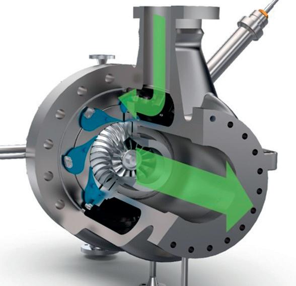
In a turboexpander (see Figure 1), high-pressure fluid passes through variable inlet guide vanes (vIGV), where potential energy is converted to high tangential velocities before entering an expander wheel in the radial direction. An ideal 90˚ turboexpander is a 50% reaction turbine, whereby approximately half of the enthalpy drop across the expander stage is used by the vIGVs to accelerate the fluid. The remaining expansion occurs in the turboexpander wheel, where the gas turns and exits at a lower pressure.
Expansion through a turboexpander is a near-isentropic process in which energy extracted from a working fluid is converted to mechanical work. This mechanical work is absorbed by a variety of devices, which are classified into two major categories: energy dissipating and energy recovery. Energy dissipating turboexpanders reject the produced work, typically in the form of heat. In contrast, energy recovery expanders convert the work to useful and free energy, often via a directly coupled booster compressor or generator. While turboexpander utility typically focuses on the energy extraction from the fluid (refrigeration), the free energy recovered by a loading mechanism can directly improve the specific power of a given process.
Figure 1. Radial inflow turbine, turboexpander.
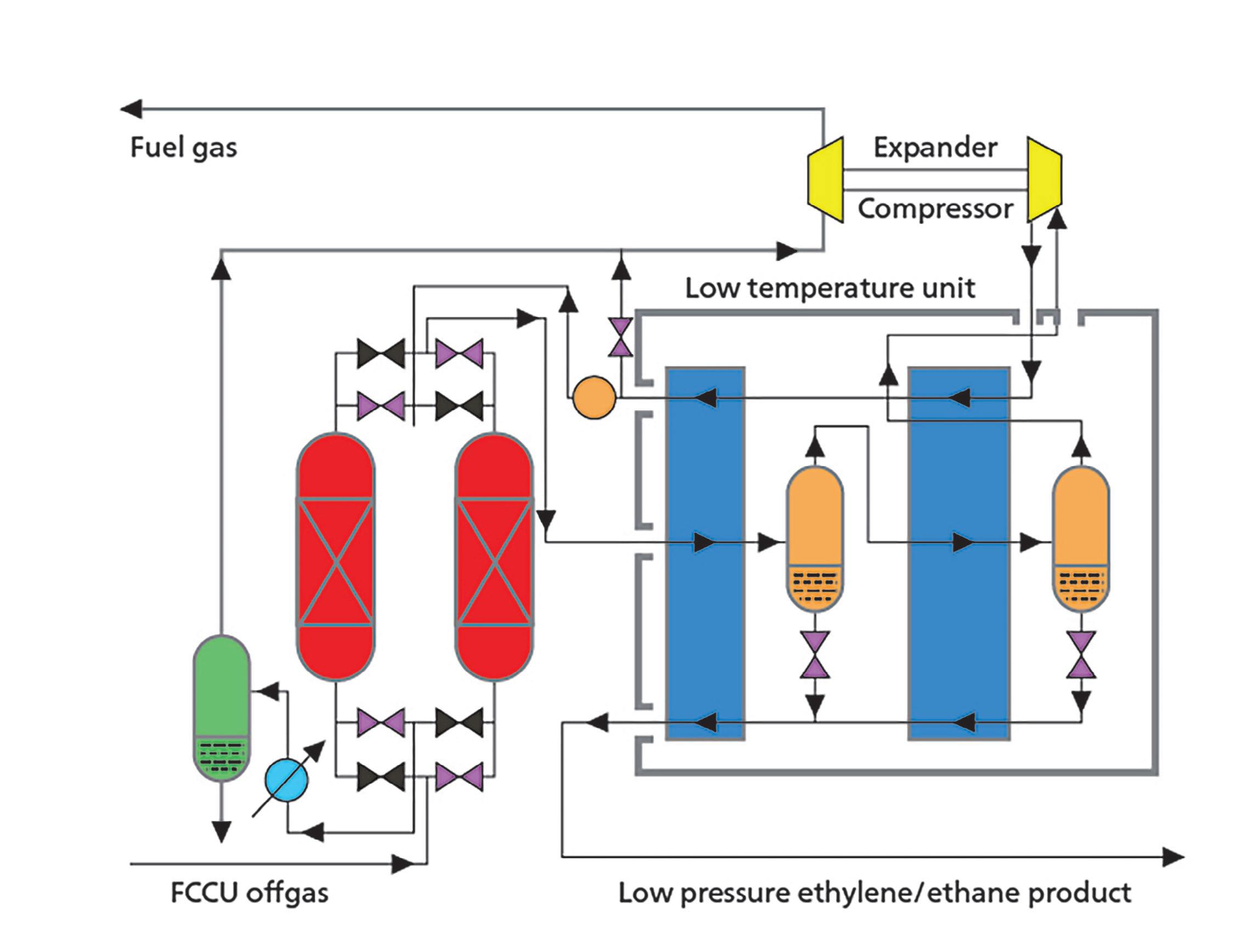
Figure 2. Ethylene treatment, distillation and recovery (source: Tomlinson 2002).
Turboexpanders and ethylene production
In ethylene, propylene or isobutylene production, turboexpanders are found in the cryogenic section of the plant, where they expand hydrogen-rich overhead vapour (off gas) to produce deep refrigeration for product recovery. These petrochemical processes require cryogenic temperatures of as low as 100 K to separate gas mixtures containing up to 96% hydrogen.
Amongst petrochemical processing, ethylene is the world’s most produced organic compound, and over the last 60 years turboexpander technology has evolved to support improved ethylene production. The manufacture of ethylene is primarily to produce polyethylene, the plastic polymer, and the introduction of turboexpanders into the distillation/recovery chill train (shown in Figure 2) of ethylene production has played a vital role in maximising plant yields.
The chill train of an ethylene plant takes advantage of byproduct propylene and the ethylene product itself as a suitable refrigerant to produce the

low-temperature cryogenic process conditions required for the ethylene product recovery. At a pressure approaching atmospheric, propylene and ethylene have boiling temperatures of -50°C and -100°C, respectively. At these temperatures, the original ethylene plant chill trains were configured to recover the bulk share of the ethylene production, with a considerable amount of ethylene carrying through with the tail gas. To improve on this, the final tail gas streams leaving the chill train units were further cooled using simple JT expansion valves.
The introduction of turboexpanders into the ethylene process over JT let-down, or the more costly methane refrigeration process, was an elegant and practical inevitability. A turboexpander is a free energy approach. The final pressure let-down from the chill train unit is provided and paid for by necessary upstream compression. A turboexpander loaded by a compressor relieves some of this upstream compression duty by recovering free work in the near isentropic expansion process. Temperature reductions in the order of 40°C across the turboexpander are common
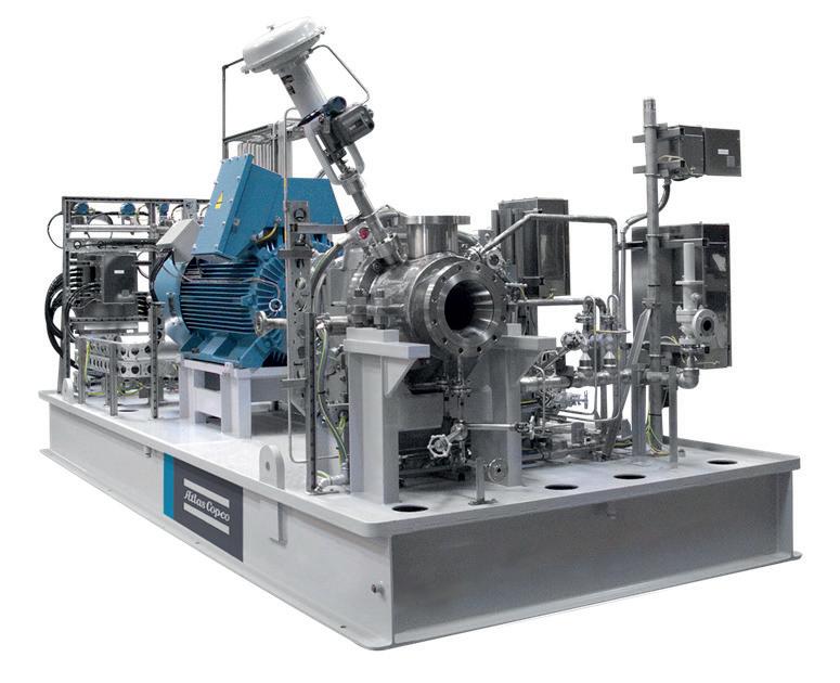
Figure 3. An expander-generator package.

Figure 4. An expander-generator (permanent magnet) with AMB.
for these process let-down conditions, adding to the chill train’s final cryogenic refrigeration loop and creating ethylene separation at temperatures of -135 to -145°C.
The big challenge for turboexpanders in ethylene plants comes from the chill train’s service factor and its absolute intolerance to any contamination that can freeze and foul out the process equipment. In fact, when using a turboexpander for high-purity hydrogen duty in an ethylene chill train, machine vendors must ensure a number of things. These include zero process contamination, robust process control by inlet guide vanes, minimal shaft seal leakage, and the ability to handle thermal cycling of start-ups and plant upsets.
Turboexpander configurations for ethylene
Turboexpanders have evolved over the years to meet the increased demand of ethylene production. As the size of ethylene plants has grown, energy recovery turboexpanders that are configured with compressors have become the preferred option. Turboexpanders paired with booster compressors offer a hermetically-sealed system with no external shaft seals. Due to sealing loss and the potential for oil carryover to the process, expander compressors equipped with active magnetic bearings (AMB) became the preference for hydrogen-rich processes when introduced in the early 1990s. AMB systems are hermetically-sealed with oil-free sealing gas fully contained in the process. Sealing gas sourced from the hydrogen-rich process cools and protects the AMB components from cold, unfiltered process gas. With no permanent magnets, AMB materials are fully compatible with hydrogen service.
Expander-compressors in hydrogen-rich applications have a unique challenge, as the process tends to demand high-head, low-flow expanders paired with high-head, high-flow compressors. This imbalance in turbomachinery geometry creates challenges with both the tip speed and rotordynamics. Turboexpander designs over the last several decades have pushed these limits, increasing customer acceptance of higher tip speed machines and optimising compressor geometry to maximise energy recovery.
Another energy recovery option used in hydrogen-rich service is the integrally-geared expander-generator. These configurations offer low-seal leakage with dry gas seals (DGS), and energy recovery via generated electricity. Typical expander-generators are not hermetically-sealed because they rely on an oil-fed gear box to reduce shaft speeds. Expander-generator packages (Figure 3) are commonly deployed in hydrogen-rich service where recompression is not required. Propane dehydrogenation (PDH), a process specific to propylene recovery, typically utilises expander-generators in a two-stage configuration.
Furthermore, innovative high-speed generators have been deployed for lighter duty applications, where gearbox cost or performance may be prohibitive for the application. In a similar arrangement to expander-compressors with AMB, permanent-magnet, high-speed generators have been arranged with two turboexpander stages rotating on a common shaft (Figure 4).1
The lessons learned from the evolution of turboexpanders in ethylene plants places the current machine configurations and vendors at an ideal point to take the next step in deeper cryogenic applications that the hydrogen industry requires.
Turboexpander design for hydrogen liquefaction
The hydrogen liquefaction process involves compression of hydrogen feed gas to the liquefier, pre-cooling normally down to 90 K, then further primary cooling down to 30 K or lower. The cooled hydrogen then expands, further reducing the temperature to near 20 K. Primary refrigeration for hydrogen liquefaction is carried out either in a Claude cycle or closed-loop Brayton cycle, often with turboexpanders operating in a refrigerant of pure hydrogen. Today’s liquefiers range from 10, 15, 30 to 40 tpd for local production, with plans for industrial scale up to 500 tpd.
Hydrogen refrigeration cycles pose several design challenges for turbomachines and material selection, high tip speed and aerodynamic considerations require evaluation when converting a traditional hydrogen-rich turboexpander to pure hydrogen liquefaction service.
The main factors determining material selections are suitability for hydrogen embrittlement, strength, and heat transfer. Some examples of suitable materials for hydrogen turbomachines are austenitic stainless steels and aluminium, depending on the effect of cryogenic temperature on their properties. Copper and other materials used in active magnetic bearings operate at relatively low temperatures, and are proven to be immune from hydrogen attack. With limitations in material selection, minimising stress from high-speed rotating components becomes an important design factor.
Most liquefier turboexpanders require high speeds in order to achieve higher performance, due to low volume and high head. With constant mass flows in the refrigeration cycle, the high enthalpy drop on the turboexpander translates to high enthalpy rise and tip speed on the booster compressor. Aluminium alloys such as 7075-T6 have outstanding strength-to-weight ratios and enable high tip speeds for both turboexpander and booster compressors.
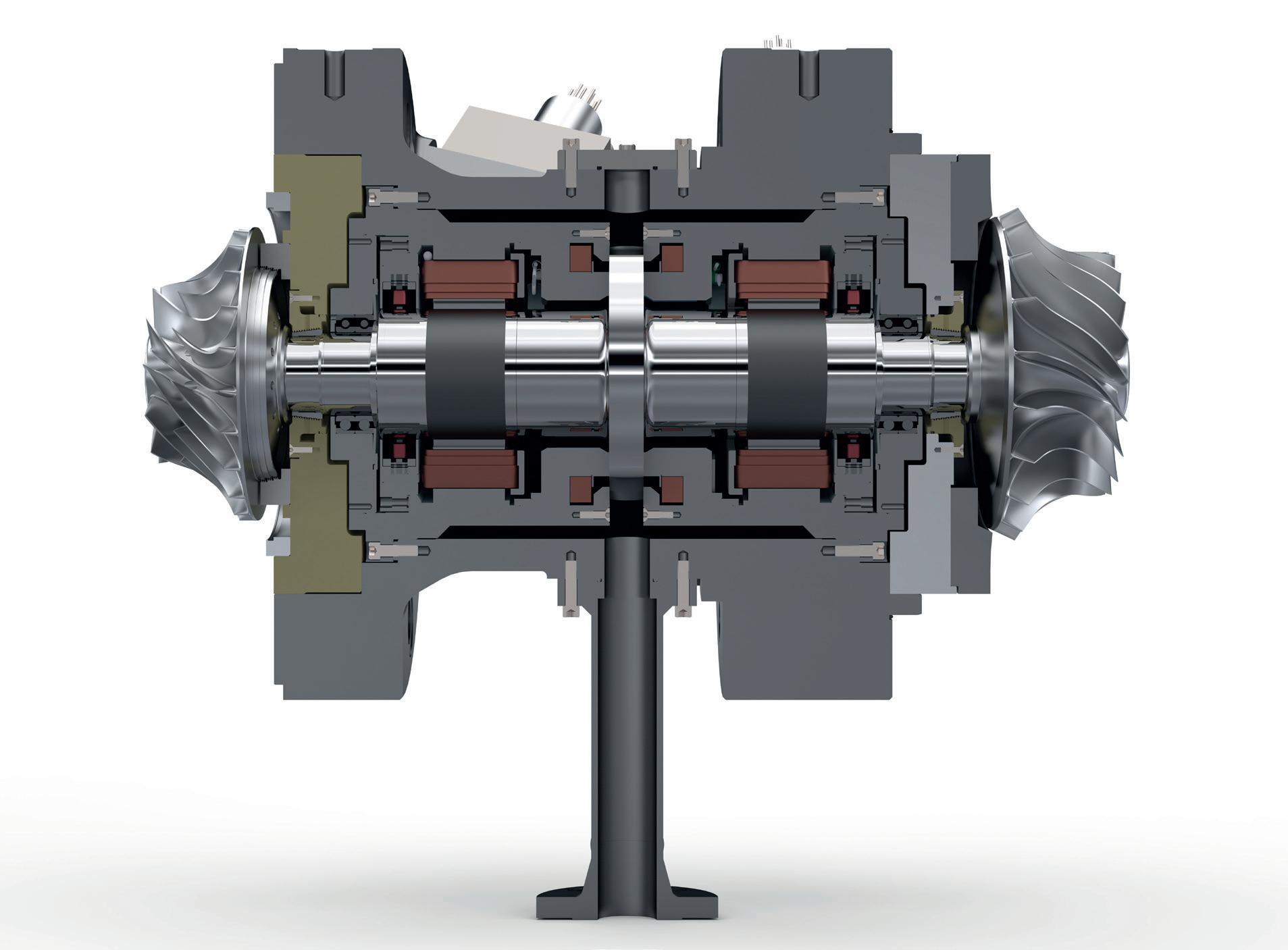
Design consideration for high tip speed include stress and deflection in the impeller disk/blade, and wheel fixation to the shaft. With proper design and feature selection, high tip speeds required for optimum aerodynamics can be achieved. The aerodynamic design must optimise blade geometries for minimising the aerodynamic losses while maintaining lower stress levels and avoiding hub and blade resonances. Because compressor boost is less important than turboexpander refrigeration, the compressor impeller design may focus more on mechanical limits rather than aerodynamic optimisation. The high specific speed compressor impeller must be custom engineered for mechanical integrity, with minimal overhung mass to improve the rotordynamics for maximum speed. Furthermore, higher head coefficient compressor designs enable smaller diameter impellers and lower tip speeds. Figure 5. Magnetic bearing rotor-bearing system.
Rotor-bearing system
Depending on the turboexpander load, cryogenic turboexpanders typically use active-magnetic, oil-lubricated, or gas bearings. Liquefier expander-compressors have a very low-pressure ratio across the compressor, making automatic thrust load control per conventional design less effective. Thrust load compensation on the expander side is not recommended since it adds to leakage and thermal losses. AMB technology (Figure 5) offers an oil-free design with improved thrust capability when compared to gas bearings, and it can typically handle the process loads without the need for additional thrust compensation. The rotor design aims to maximise the speed with the required double overhung impeller weights, and maximise thrust load capacity to cover different process conditions.
Conclusion
Turboexpanders have been used extensively in hydrogen-rich applications in the petrochemical industry for the last half century. Developments in the petrochemical industry over decades are now being adapted to the demands of green hydrogen liquefaction. Turboexpander design for hydrogen liquefaction requires challenging aerodynamics, high tip speeds, innovative sealing systems, minimal clearance losses, suitable material selections, and robust thermal management. Numerous hydrogen-rich turboexpanders designed and operating in the field have validated the design process. With careful evaluation, these machines can be adapted and qualified for hydrogen liquefaction at all scales.
Note
• This article was originally presented at the Asia Turbomachinery and Pump Symposium 2022, Kuala Lumpur, Malaysia. * Behrooz Ershaghi (retired from Atlas Copco Gas and Process) contributed to the original article as a co-author.
Reference
1. VITT, J., and MAYNE, T., ‘Expander boosts ethylene recovery’,
Turbomachinery International, (January/February 2021), pp. 26 – 27.
Bibliography
• TOMLINSON, T. R., ‘Improved operating margins with ethylene recovery’, Petroleum Technology Quarterly, (Spring 2002), pp. 125 – 131.


