
8 minute read
Blast test demonstration



Dean Alcott, RedGuard, USA, details how a large-scale test demonstrates efficacy of steel blast-resistant modules.

On 23 March 2005, a massive explosion at a Texas City refi nery in the US during the restart of an isomerisation unit led to 15 deaths and 170 injuries. The majority of the casualties were workers offi ced in temporary non-blast rated wooden offi ce modules. At the time, the American Petroleum Institute (API) Recommended Practice 752 (RP752), ‘Management of Hazards Associated with Location of Process Plant Buildings’ had been in place for 10 years. It presented siting guidance for new ‘stick-built’ structures and hazard analysis guidance. However, the RP752 did not take into consideration the safe siting of temporary buildings. The standard for siting of temporary buildings Recommended Practice 753 (RP753), ‘Management of Hazards Associated with Location of Process Plant Portable Buildings’, was released in 2007 in large part to address the dangers exposed in Texas City.
Even with the adoption of RP753 and all of the process safety changes made in the last 15 years, the danger is still great in hydrocarbon processing plants and the upstream feed. In 2020, there were 71 deaths and 216 injuries worldwide in refi neries, petrochemical plants, and in relation to pipelines.
As part of required quantitative risk assessments (QRAs) in process plants, engineers determine safe siting for portable buildings to protect them from fi re, gas and vapour cloud explosions. In congested facilities where the buildings cannot practically be sited outside of identifi ed blast hazard areas, buildings must be engineered to protect occupants from the hazards. In the case of protection from a vapour cloud explosion, this protection can come in the form of a blast-resistant module (BRM).


Blast-resistant modules
Before examining how to fabricate and test a BRM, it is important to consider the forces it is designed to mitigate. A vapour cloud explosion is exactly as it sounds – it can originate in a broken pipe or valve, or an overfl owing distillation tower as demonstrated by the Texas City example. Due to the temperatures and pressures of many of the refi ning processes, a


release to the atmosphere causes the hydrocarbons to vaporise. If not stopped quickly, this vapour forms a cloud close to the ground. Once that cloud fi nds an ignition source, an explosion can take place, often setting off multiple explosions. When large vapour clouds form, explosions will have longer durations (50 – 200 msec.) than, for example, a weapon’s discharge. Ultimately, this means BRMs must withstand forces over a longer duration than a building used for military applications, such as a military guardhouse.
Once the engineers have identifi ed the blast zones, not every petrochemical plant or refi nery may need to consider the implementation of BRMs. However, in some cases, a QRA may conclude that an existing building is now in a blast zone due to process changes. In some cases – typically with lower blast ratings – these buildings can be retrofi tted. This work must be designed by an engineer with specifi c blast protection experience, and performed by qualifi ed contractors. Retrofi ts vary greatly from simple glass replacement to signifi cant structural changes. Sometimes the simplest solution is to pull the people and buildings out of the blast zone and relocate them to non-blast areas. It is important to consider process control and process safety, as well as work effi ciency.
In cases where new space is required, a modular solution such as a BRM can provide a fast and cost-effi cient solution. Onsite disruption is minimised and weather delays are eliminated, as the modules are built in a factory. The design, fabrication, assembly, quality control and testing are performed by people who make blast-resistant buildings every day.
RedGuard and RedGuard Specialist Services have carried out multiple large-scale blast tests to prove the effi cacy of the companies’ steel designs. The fi rst was carried out in 2007, at the beginning of the BRM industry, using 567 kg of ammonium nitrate and fuel oil (ANFO). The second was completed in 2020 with 2721 kg of ANFO. The purpose of the larger charge weight and longer standoff distance was to increase the blast wave duration on the buildings, while also applying a high blast pressure. The live blast test also validates structural computer modelling and challenges basic structural design assumptions. Various accessories were also tested, such as windows, blast anchors, and intumescent coating.
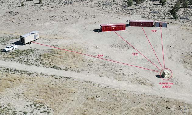
Figure 1. Layout of the blast test.
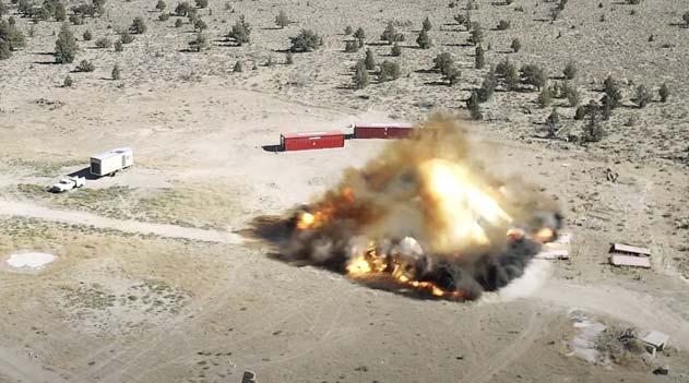
Figure 2. Blast test explosion.
Test set-up
Figure 1 shows the layout of the blast test. The test arena was located in Deschutes County, Oregon, US. The test structures included: An anchored 12 ft x 40 ft (3.6 m x 12 m) BRM (10 psi 200 ms) to model the typical installation of a custom, permanently installed BRM. Internally, the unit had typical finishes, a dividing wall and a desk with a crash test dummy to simulate human response. An unanchored 12 ft x 40 ft (3.6 m x 12 m) BRM (8 psi 200 ms) to model the typical installation of a temporary rented unit. An unanchored 8 ft x 20 ft (2.4 m x 6 m) BRM (8 psi 200 ms) with a window and intumescent coating to test coating adhesion during a blast, and to test window performance during the blast. A wooden trailer similar to the previously described
Texas City buildings. An old truck provided by the test laboratory to observe the reaction.
With the buildings and truck in place, RedGuard and the testing company spent nearly a week installing a wide array of measurement devices, including: Interior and exterior pressure gauges. Free-field pressure probes. Decibel metres. Load cells. Anthropomorphic test device (ATD), also known as a
‘crash test dummy’. Passive sliding measurements. Accelerometers. Linear encoders.
When designing a BRM, each component must be analysed for its reaction to the blast. The combination of all components must withstand the free-fi eld blast pressure, blast duration, and not exceed the designed damage level per the American Society of Civil Engineers (ASCE). The ASCE levels are low, medium and high response: Low – localised component damage. Building can be used, however repairs are required to restore the integrity of the structural envelope. Total cost of repairs is moderate. Medium – widespread component damage. Building should not be occupied until repaired. Total cost of repairs is significant. High – key components may have lost structural integrity and building collapse due to environmental conditions
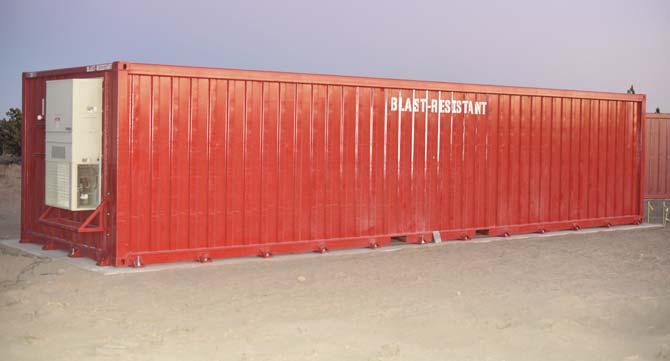
Figure 3. Anchored unit before the blast.
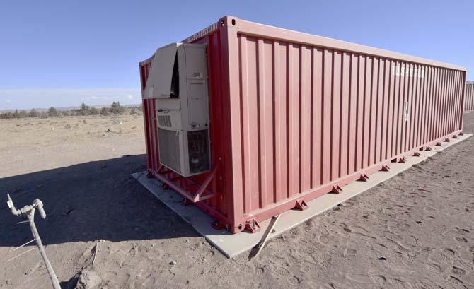
Figure 4. Anchored unit after the blast.
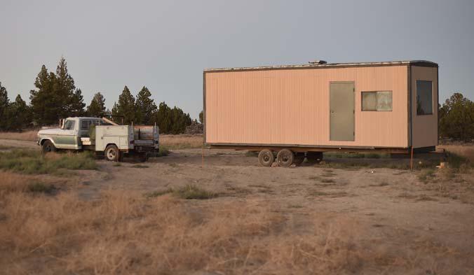
Figure 5. Wooden trailer before.
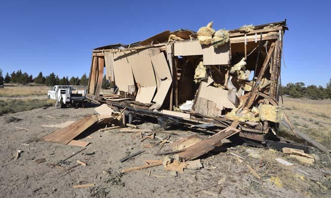
Figure 6. Wooden trailer after. may occur. Total cost of repairs approaches replacement cost of the building.
RedGuard and RedGuard Specialist Services only design buildings to low or medium response levels due to concern about occupants in a building that has lost structural integrity. It takes more steel and a more conservative design to achieve low and medium response.
After the blast test, when data from the above instruments is collected, a huge amount of effort goes into analysing defl ection or deformation of all measured components to be sure that the intended design is met.
The blast
Figure 2 shows the blast wave propagating towards the test buildings, as fi lmed by a drone. The blast was created from 2721 kg of ANFO, slightly elevated in the centre of the arena.
The following is an excerpt of the test pressures generated by the blast:
Anchored building
Peak pressure front face: 23.5 psi. Peak pressure roof: 10.6 psi. Peak pressure back face: 4.7 psi. Free field pressure: 9.9 psi near the anchored building, 7.5 psi near wooden trailer.
The full test report is 254 pages, and the companies collected nearly a terabyte of data, photos and video. It is impossible to share all of this information in a single article, but to offer an understanding as to why BRMs are used, refer to Figure 3 and Figure 4 for the before and after of the 12 ft x 40 ft anchored BRM. It sustained no structural damage, whereas the wooden trailer was completely destroyed (as seen in Figure 5 and Figure 6).
Test conclusions:
The three BRMs all survived the blast with little or no damage. All would satisfy the requirements for low damage level as per ASCE specifications. The wooden trailer surpassed the high damage level and collapsed. BRM doors and windows remained functional after the blast, and the intumescent coating remained intact for later successful fire testing. Based on force and acceleration data collected on the crash test dummy, it is estimated that BRM occupants would suffer minor to no injury. This conclusion is based on pressure sensors, accelerometers and sound measurement inside the BRM. The unanchored buildings moved less than 5 cm in the blast.
To summarise, the amount of real data that can be collected and applied to BRM designs from a live blast test is incredible. Given the critical life-saving role of these buildings, live tests are vital. The live test confi rmed RedGuard’s computer modelling and, in some cases, showed the company where its designs were too conservative and could be modifi ed for effi ciency.


