10 minute read
A leap forward in expandable liner technology


A leap forward in

EXPANDABLE LINER EXPANDABLE LINER
TECHNOLOGY TECHNOLOGY


Matt Godfrey, Enventure Global Technology,
USA, outlines the features of a new development in expandable liner technology and describes its successful application in a commercial well.


The SameDrift expandable mono-diameter liner, the latest development in expandable technology by Enventure Global Technology, allows wells to be designed for a larger envelope of capabilities. It was developed with the goal of isolating fluid losses or wellbore intrusion encountered while drilling, thus enabling optimal inner diameter (ID) during extended reach drilling. The liner also includes several other advantages that only come with a mono-diameter system. Planned-in and/or contingency SameDrift liners will ensure that trouble zones are isolated from the start, with no effect on the diameter of the wellbore, completion design or other wellbore contingencies. Maintaining the same drift means operators can reach their extended reservoir section at planned or larger ID to optimise production rates. The liner also opens opportunities for reducing costs by implementing light casing designs. High departure wells tend to use multiple casing strings to reach target depth (TD) with an acceptable ID; SameDrift can be planned-in to minimise the need for intermediate or isolation strings, thus reducing the cost of casing, mud and cement as well as rig time.
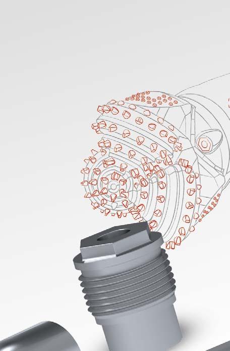
The liner is deployed with an expansion assembly on drill pipe made up at the bottom of an expandable liner string. The expansion assembly enables torque to be transmitted to the liner while running in hole, allowing full rotation of the system. Once run in to TD, the liner may be cemented in place, or uncemented using conventional or swellable elastomers to clad into the openhole. The expansion assembly contains a segmented cone that forms downhole using a jack mechanism. Expansion is initiated by landing a wiper dart into the shoe at the bottom of the expandable liner


to create a pressure chamber. Pressure is increased, causing the jack to activate and stroke the cone segments together into a fully built conical shape, while radially expanding the liner in the process. A casing lock, which carries the weight of the liner while running in hole, is mechanically timed to release the casing when the cone is formed and locked to full diameter. Expansion begins at this point, as indicated by a clear pressure and hook load drop at the surface. Through the combined use of overpull and hydraulic pressure, the entire length of the liner is expanded from bottom up in a similar operation to conventional solid expandable liners by leaving the liner shoe at TD.
Once the liner has been expanded, the fully built cone exits the top of the release joint. The release joint contains a proprietary connection that is designed to part as the cone expands through, creating the re-entry guide for subsequent operations through the expanded liner. It also allows the final few feet of the liner to be expanded with a combination of hydraulic force and overpull, rather than relying solely on overpull and risking dragging the liner up hole and out of position.


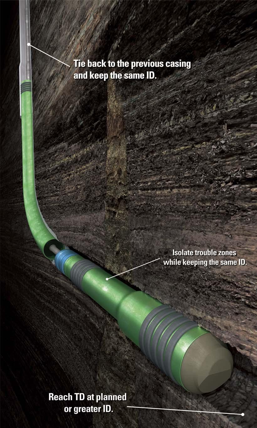
Figure 1. Extend casing strings or isolate multiple trouble zones.
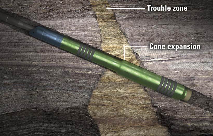
Figure 2. One-trip expansion: expansion only takes one trip and is continuous from the bottom to the top, which lowers non-productive time.
After the cone exits the release joint, the cone’s diameter is too large to convey back to the surface. A retract ball is dropped, which unlocks the cone and shifts the cone into its smaller segmented outer diameter (OD), allowing the expansion assembly to be pulled out of hole and leaving the expanded liner in place.
The expanded liner may either be deployed as an openhole clad, which is a liner that covers and isolates the trouble section of the openhole, or as a planned-in liner. In the application of installing SameDrift as a planned-in liner and/or contingency, a short receptacle is required to clad into and tie the system back to the previous base casing string. The receptacle is a section of the larger OD/ID casing crossed over at the bottom of the previously installed casing string. Its length is determined by the length of the expandable liner, the post-expanded shrinkage calculation and the pilot hole length, and is typically just a few joints in length. Both methods require the formation to be drilled and underreamed, in order to provide radial space to allow for the SameDrift liner to be expanded and to allow for a good cement bond around the expanded liner. A key advantage of the technology is that it allows for subsequent clads of the same drift diameter to be run in below the previous clad or liner.
SameDrift is currently commercially available in three post-expanded drift sizes: 6 1/2 in., 8 1/2 in. and 12 1/4 in. The 12 1/4 in. size is available in standard and high performance (HP) versions. The HP version offers increased burst and collapse ratings, if required. During the development phase of the tool, extensive use of finite element analysis and other stress state calculations were employed to verify the strength and dynamics of the internal mechanisms and their functionality in a wide range of potential wellbore environments. This approach ensures that the mechanisms are robust enough to function as intended downhole.
Each commercially available size has been successfully tested in a laboratory setting and downhole on a test rig environment to verify the functionality of the internal mechanisms, including cone build, expansion, cladding and cone retraction. In addition to testing the normal tool functionality, there are several built-in contingency mechanisms within the tool to allow the operator to release the expansion assembly from the liner in the event that the liner becomes stuck. These contingency scenarios have also been successfully tested in the laboratory and downhole.
Case study
During 3Q20, the 12 1/4 in. Standard Wall SameDrift was successfully deployed in a commercial well, with all installation objectives being met. This application was a planned-in installation as an openhole clad. Total unexpanded clad length was 251 ft. In this application, the operator had set 13 3/8 in. casing and was drilling the 12 1/4 in. section below while underreaming to 13 1/4 in., starting at the bottom of the 13 3/8 in. shoe at 5325 ft to TD at 5748 ft. This installation was elected to be installed as an openhole clad and rely on anchor hangers to provide isolation of the section rather than cementing. The anchor hangers are a joint of expandable pipe with
an elastomer element bonded to the outside. As the openhole clad is expanded, the anchor hanger is compressed either against the formation or casing to provide an anchor and a seal. A caliper run was performed prior to the installation to gauge the openhole section and determine the most eff ective placement of the anchor hangers along the liner string.
The openhole clad was made up to length with four precisely located anchor hangers and run in hole to TD on 5 in. drill pipe. Using a safety sub connection, the drill pipe was stabbed into the expansion assembly at the bottom of the expandable openhole clad. Lastly, prior to running in hole, the release joint was stripped over the drill pipe and made up as the upper most joint in the expandable openhole clad.
The openhole clad was then run to TD, and the wiper dart was loaded and pumped through the drill pipe at 4 bbl/min. and 300 psi until it landed in the shoe. Pressure integrity was verified, and pressure was increased at 1/4 bbl/min. until verification that the cone was formed and locked. The cone was fully formed at 3700 psi, and expansion began. This was verified by clear indications of hook load drop and pressure drop at the surface. Flowrate was increased to 2 to 3 1/2 bbl/min. once operations shift ed from cone building to expansion mode. The first stand was expanded with pressures fluctuating between 2100 and 2500 psi. Expansion continued in this range until all three stands were expanded and the cone exited the top of the release joint, signalled by a total loss of pressure. Once expansion was complete, the cone retract ball was dropped to seat within the expansion assembly. Pressure was increased to 2800 psi until the cone retraction was verified by a subsequent loss in pressure and regain of circulation. Tools were tripped out of hole and laid down at the surface.
Once the openhole clad was expanded, a mill run was performed to drill out the shoe, dart and float equipment. Milling was completed with an 11 in. junk mill and 13 ¼ in. section mill. Once milling was completed, the openhole clad was drift ed and confirmed to have a 12 1/4 in. post-expanded drift , indicating a successful installation.
With the 12 ¼ in. drift expanded openhole clad in place, the client was able to drill a 12 1/4 in. openhole beneath the expanded openhole clad for an additional 2113 ft . An extensive formation sampling programme was then undertaken by the client with two wireline logging runs and three conditioning bottomhole assemblies (BHAs) through the installed openhole clad. The subsequent 9 5/8 in. conventional liner string was run through the SameDrift openhole clad and cemented back into the 13 3/8 in. base casing string. The successful operations through the 12 1/4 in. openhole clad were used as confirmation of the overall success of the installation. The value added to the client was a system that can be used to isolate losses or trouble formations without losing drift diameter, allowing for continued drilling with the same BHA through trouble zones without deviating from the planned well completion.
Conclusion
In summary, the SameDrift openhole liner or openhole clad can provide permanent isolation of weak formations and ensure optimal ID at TD. The technology enables optimum fluid design, which reduces formation instability and non-productive time as well as the chances of lost BHAs. SameDrift also enables optimum well design to further step out for extended reach applications.